Table of Contents
Advertisement
Quick Links
Advertisement
Chapters
Table of Contents
Troubleshooting

Related Manuals for Patton electronics NetLink 1001MC


Summary of Contents for Patton electronics NetLink 1001MC
-
Page 1: Operations Guide
Model 1001MC NetLink™ SNMP Management Card Operations Guide Sales Office: +1 (301) 975-1000 Technical Support: +1 (301) 975-1007 E-mail: support@patton.com WWW: www.patton.com Document Number: 022021U Rev. F Part Number: 07M1001MC Revised: May 19, 2008... - Page 2 Patton Electronics Company, Inc. 7622 Rickenbacker Drive Gaithersburg, MD 20879 USA tel: +1 (301) 975-1000 fax: +1 (301) 869-9293 support: +1 (301) 975-1007 url: www.patton.com e-mail: support@patton.com Copyright Statement Copyright © 2008, Patton Electronics Company. All rights reserved. Trademark Statement The terms NetLink , KiloModem , and MegaLink-I are trademarks of Patton Electronics Company.
-
Page 3: Table Of Contents
Introduction ..............................10 Introduction ................................11 Model 1001MC management overview.........................14 Hardware installation............................ 15 Introduction ................................17 Installing the Model 1001MC into the rack chassis ....................18 Installing NetLink modem cards ...........................19 Installing the power supplies..........................31 Verifying 1001MC functioning..........................31 Connecting the cables............................32 LED indicators ..............................34... - Page 4 Model 1001MC Operations Guide Contents Using the Download page to upgrade 1094ARC software ..................87 Model 1095RC management......................... 89 Introduction ................................92 Configuration and management ..........................92 Modem Information page MIB variables description...................101 Model 1095 Configuration Slot page MIB variables description................104 Model 1095 Configuration—Next Configuration page MIB variables description ..........107...
- Page 5 Model 1001MC Operations Guide Contents Download................................249 System Log ................................251 System Log—Modify ............................252 System Log—Volatile Memory..........................256 System Log—Non-Volatile Memory ........................257 SNMP .................................258 System Config ..............................259 Help ..................................275 Troubleshooting and maintenance ......................276 Introduction ................................277 Troubleshooting the 1001MC rack card......................277 Troubleshooting network malfunctions .......................278...
-
Page 6: About This Guide
(on page 15) describes how to install the Model 1001MC • Chapter 3 (on page 36) describes how to boot the Model 1001MC, install cables, set up the address range for NetLink modems, log into the HTTP/HTML administration pages, and save HTTP/HTML object changes •... -
Page 7: Typographical Conventions Used In This Document
About this guide Model 1001MC Operations Guide Typographical conventions used in this document This section describes the typographical conventions and terms used in this guide. General conventions The procedures described in this manual use the following text conventions: Table 1. Text conventions... -
Page 8: Additional References
When you have moved the mouse pointer to the desired location, you can release the mouse button. Additional References The Patton Electronics website (www.patton.com) provides 1001MC and NetLink modem application notes, which includes FAQ, startup notes, and test setups. RFCs Use a web browser to find online copies of the following requests for comments (RFC) documents:... - Page 9 About this guide Model 1001MC Operations Guide Service All warranty and non-warranty repairs must be returned freight prepaid and insured to Patton Electronics. All returns must have a Return Materials Authorization number on the outside of the shipping container. This number may be obtained from Patton Electronics Technical Services at: •...
-
Page 10: Introduction
Chapter 1 Introduction Chapter contents Introduction ................................11 Model 1001MC management overview.........................14... -
Page 11: Introduction
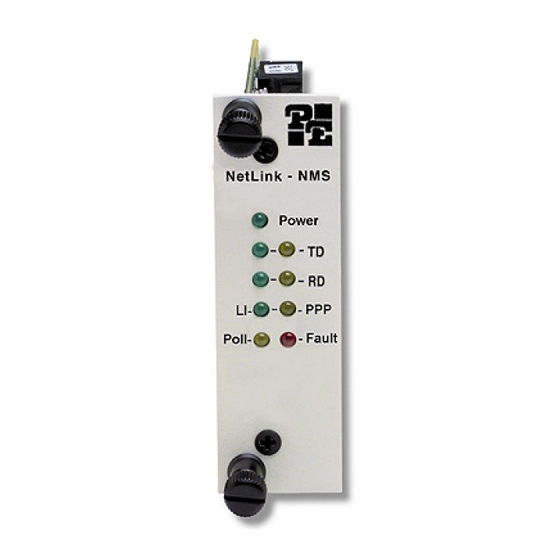
Model 1001MC Operations Guide 1 • Introduction Introduction The Model 1001MC NetLink™ SNMP Management Card (see figure 1) enables an SNMP workstation to configure and monitor multiple Patton NetLink cards racks and their connected standalone units. Figure 1. Model 1001MC NetLink Management Card The management card has the following features: •... - Page 12 Model 3088RC G.SHDSL X.21 - DB15 Model 3088RC G.SHDSL E1 - Dual BNC & RJ-45 Model 3088RC G.SHDSL Ethernet BR - RJ-45 Note Your specific model of 1001MC may not support all of the models listed above. The 1001MC front and rear cards (see figure 2) install into the Model 1001R14/16 NetLink Rack Chassis (see figure...
- Page 13 Model 1001MC Operations Guide 1 • Introduction Figure 3. Model 1001R14/16 Rack Chassis with power supply Introduction...
-
Page 14: Model 1001Mc Management Overview
Model 1001MC management overview The Model 1001MC uses a 10Base-T Ethernet port to connect to a local LAN (or to any location in the world via the Internet). Management can be performed using any SNMP station or web browser with the internal HTTP/HTML management screens. -
Page 15: Hardware Installation
Hardware installation Chapter contents Introduction ................................17 Before you install… ............................17 Checking the contents… ..........................17 Installing the Model 1001MC into the rack chassis ....................18 Installing NetLink modem cards ...........................19 Hardware setup for a Model 1092ARC ......................19 Configuring frame ground ........................19 Setting the 1092ARC system address ......................20... - Page 16 Model 1001MC Operations Guide 2 • Hardware installation Installing the Ethernet cable ..........................32 Connecting a 10Base-T hub to the 1001MC ....................33 Connecting a 10Base-T workstation to the 1001MC ................33 Installing the RS-232 configuration/daisy-chain port cable ................34 LED indicators ..............................34 Ethernet LED indicators ..........................35...
-
Page 17: Introduction
A VT100 terminal or a VT100 terminal emulator for connection to the RS-232 configuration port • A null modem or a null modem cable to connect your VT100 terminal to the Model 1001MC • An Ethernet connection to your local LAN •... -
Page 18: Installing The Model 1001Mc Into The Rack Chassis
2 • Hardware installation Figure 5. Rack chassis slot layout (rear view) Installing the Model 1001MC into the rack chassis The Model 1001MC consists of a front rack card and a rear input/output (I/O) card (see figure 2 on page 12). -
Page 19: Installing Netlink Modem Cards
“Hardware setup for a Model 3088RC” on page 29) Hardware setup for a Model 1092ARC The following must be done to configure your Model 1092ARC hardware for use with the Model 1001MC network management station: • Connect frame ground to signal ground (see section “Configuring frame... -
Page 20: Setting The 1092Arc System Address
1001MC will automatically set the number of slots available (displayed on the Modem Informa- tion page) in the chassis to 13. If the system is set for a single power supply installed, the 1001MC will auto- matically set the number of slots available in the chassis to 15. - Page 21 Model 1001MC Operations Guide 2 • Hardware installation from the power supplies) and increment the numbers by one as you go from left to right. Setting the addresses in this manner will make configuration easier as you start using the web page management. An example of this is shown below.
-
Page 22: Hardware Setup For A Model 1094Arc
1001MC will automatically set the number of slots available (displayed on the Modem Informa- tion page) in the chassis to 13. If the system is set for a single power supply installed, the 1001MC will auto- matically set the number of slots available in the chassis to 15. - Page 23 Model 1001MC Operations Guide 2 • Hardware installation address 1 to address 13. The 1001MC will then begin polling rack #2 on the daisy chain port starting from address 14. The daisy chained racks are set up in the same manner with 13 addresses being available in a redundant system and 15 addresses being available in single supply system.
-
Page 24: Hardware Setup For A Model 1095Rc
1001MC will automatically set the number of slots available (displayed on the Modem Informa- tion page) in the chassis to 13. If the system is set for a single power supply installed, the 1001MC will auto- matically set the number of slots available in the chassis to 15. - Page 25 The 1001MC is always address 0. The 1001MC will then begin polling rack #2 on the daisy chain port starting from address 16. In a redundant power supply system, the address range for rack #1 (the rack with the 1001MC installed) will be from address 1 to address 13.
-
Page 26: Hardware Setup For A Model 2701Rc
0x02 (2) 0x10(16) 0xB5(181) Hardware setup for a Model 2701RC The following must be done to configure your Model 2701RC hardware for use with the Model 1001MC net- work management station: • Connect frame ground to signal ground (see section “Configuring frame... -
Page 27: Setting The 2701Rc System Address
1001MC will automatically set the number of slots available (displayed on the Modem Informa- tion page) in the chassis to 13. If the system is set for a single power supply installed, the 1001MC will auto- matically set the number of slots available in the chassis to 15. -
Page 28: Hardware Setup For A Model 2707Rc
0x02 (2) 0x10(16) 0xB5(181) Hardware setup for a Model 2707RC The following must be done to configure your Model 2707RC hardware for use with the Model 1001MC net- work management station: • Connect frame ground to signal ground (see section “Configuring frame... -
Page 29: Hardware Setup For A Model 2710Rc
Model 1001MC Operations Guide 2 • Hardware installation Hardware setup for a Model 2710RC The following must be done to configure your Model 2710RC hardware for use with the Model 1001MC net- work management station: • Connect frame ground to signal ground (see section “Configuring frame... -
Page 30: Polling Overview
1001MC will automatically set the number of slots available (displayed on the Modem Informa- tion page) in the chassis to 13. If the system is set for a single power supply installed, the 1001MC will auto- matically set the number of slots available in the chassis to 15. -
Page 31: Installing The Power Supplies
Verifying 1001MC functioning 1. Apply power to the rack system, verify that the green Power LED on the Model 1001MC front card illumi- nates. 2. Turn off power to the rack system, verify that the green Power LED on the Model 1001MC front card extinguishes. -
Page 32: Connecting The Cables
34). Figure 9. Rear I/O card ports Installing the Ethernet cable The RJ-45 Ethernet jack on the rear I/O card of the Model 1001MC is designed to connect directly to a 10Base-T network. Figure 10 shows the RJ-45 jack pin-out diagram. Refer to the following sections when con- structing Ethernet cables to connect to the Patton Model 1001MC. - Page 33 2 • Hardware installation Connecting a 10Base-T hub to the 1001MC The Ethernet 10Base-T port on the rear of the 1001MC connects directly to a 10Base-T hub or repeater using RJ-45 unshielded twisted-pair cable that is wired straight-through (see figure 11).
-
Page 34: Led Indicators
1001CC in a separate rack if you are daisy-chaining multiple racks. Figure 13. RS-232 DTE configuration port Note The configuration port on your 1001MC, being a DTE, requires a null modem or equivalent cable when connecting to a terminal. Using personal computer communications software (Procomm, Windows Terminal, BitCom, PC Anywhere, etc.), set the configuration of your communications software to the following parameters:... -
Page 35: Where To Go Next
The PPP capability will be included in future releases as a software upgrade to the 1001MC. Where to go next Congratulations, you have finished installing the Model 1001MC! Now go to chapter 3, “Getting started” page 36. Where to go next... -
Page 36: Getting Started
Getting started Chapter contents Introduction ................................37 Booting the Model 1001MC ..........................37 Installing the Model 1001MC RS-232 daisy-chain port cable ................39 Setting the address range for your NetLink modems ..................40 Introduction to the internal HTTP/HTML management pages ................41 Logging into the HTTP/HTML administration pages ..................41... -
Page 37: Introduction
1001MC through a null-modem. The RS-232 port is configured as data terminal equipment (DTE). 3. Apply power to the rack system. The Model 1001MC will begin a series of diagnostic tests to exercise the internal sub-systems in the unit. You must halt the power up sequence in order to enter a new IP address, mask, and default gateway into the box. - Page 38 5. After entering the information, the system will prompt you to save the IP settings. Type Y to save the new settings. 6. The Model 1001MC will prompt you for changes to the hardware revision that your unit requires as follows:...
-
Page 39: Installing The Model 1001Mc Rs-232 Daisy-Chain Port Cable
8. Disconnect the cable from the rear panel RS-232 configuration port of the 1001MC. 9. If you are installing a daisy-chain cable to the RS-232 configuration port of the 1001MC, go to section “Installing the Model 1001MC RS-232 daisy-chain port cable”. -
Page 40: Setting The Address Range For Your Netlink Modems
The Model 1001MC polls the system looking for NetLink modems. If the address of the NetLink modem is not configured or does not match the rack that it is installed in, the Model 1001MC may not find the card. The address range that is polled is determined by the configuration of the system. The system administrator must make sure that the software configuration within the Model 1001MC matches the hardware configura-... -
Page 41: Introduction To The Internal Http/Html Management Pages
#1 (the rack with the 1001MC installed) will be from address 1 to address 13. The 1001MC will then begin polling rack #2 on the daisy chain port starting from address 14. -
Page 42: Saving Http/Html Object Changes
1001MC is power-cycled. Help screens The Model 1001MC web pages have built-in help screens that enable you to get information about the vari- ables that are being described. Each web page contains several headings that describe the section that is being defined. - Page 43 Model 1001MC Operations Guide 3 • Getting started Figure 18. 1001MC command map Saving HTTP/HTML object changes...
-
Page 44: Home
1001MC to perform a reset. This will not reset the individual cards in the Hard Reset rack only the 1001MC. If you would like to perform a hardware reset on the individual cards, refer to the Slot Configuration page. For more information, refer to section “HOME”... -
Page 45: Configure Cards
Syslog messages. Syslog messaging is a reporting tool used in the Model 1001MC to log run-time operations. There are several levels of messages and you can set the system to report only messages above a certain level. For more information, refer to section “System Log”... -
Page 46: Where To Go Next
“Model 2707RC management” on page 167 • Chapter 9, “Model 3088RC management” on page 187 For more detailed information about Model 1001MC management web pages, refer to chapter 10, “HTTP/HTML web page reference” on page 220. Where to go next…... -
Page 47: Model 1092Arc Management
Chapter 4 Model 1092ARC management Chapter contents Introduction ................................49 NetLink-NMS description ..........................49 Configuration and management ..........................49 Displaying the Modem Information page .......................50 Displaying the Model 1092 Configuration Slot page ..................52 Making configuration changes to your 1092ARC NetLink modem ............53 Displaying the Model 1092 Configuration—Next Configuration page ............54 Displaying the Slot Configuration page ......................56... - Page 48 Model 1001MC Operations Guide 4 • Model 1092ARC management HW Test Mode (testModeIndiDSL/remotetestModeIndiDSL) ..............62 SW Test Mode (testModeSetiDSL/remotetestModeSetiDSL) ..............62 Software Rev (softVersioniDSL/remotesoftversioniDSL) ................63 Model 1092 Configuration—Next Configuration page MIB variables description ..........63 Card Address (nmsSlotID) ..........................63 Line Status (lineStatusiDSL) ...........................63 Processor Mode (processorModeiDSL) ......................63...
-
Page 49: Introduction
SNMP management can be performed on both the local and remote units using a standard SNMP network man- agement station (NMS) or by using a standard web browser and the Model 1001MC’s built-in web server. You can view and change configuration variables, view statistical variables, and view error and warning indications. -
Page 50: Displaying The Modem Information Page
Model 1001MC Operations Guide 4 • Model 1092ARC management Displaying the Modem Information page Modem Information page (see figure 20) displays the cards installed in the system and a quick view of any errors or warnings associated with your modems. - Page 51 Model 1001MC Operations Guide 4 • Model 1092ARC management Figure 21. Web page navigation to Modem Information page Configuration and management...
-
Page 52: Displaying The Model 1092 Configuration Slot Page
Model 1001MC Operations Guide 4 • Model 1092ARC management Displaying the Model 1092 Configuration Slot page Model 1092 Configuration Slot page (see figure 22) enables you to make configuration changes to the Model 1092A and the remote CPE box. When the page displays, the unit is set to the onLine state and the cur- rent configuration is displayed. -
Page 53: Making Configuration Changes To Your 1092Arc Netlink Modem
3. Make your configuration changes or select the button. Set Default Configuration 4. Select the button to place the changes into the 1001MC’s temporary memory. If you decide Submit Query that you do not want your changes implemented, you can select the Clear Changes button. -
Page 54: Displaying The Model 1092 Configuration-Next Configuration Page
Model 1001MC Operations Guide 4 • Model 1092ARC management Displaying the Model 1092 Configuration—Next Configuration page Model 1092 Configuration—Next Configuration page (see figure 24) enables you to make configuration changes to the Model 1092A and the remote CPE box. When the page displays, the unit is set to the onLine state and the current configuration is displayed. - Page 55 Model 1001MC Operations Guide 4 • Model 1092ARC management Figure 25. Web page navigation to Model 1092 Configuration—Next Configuration page Configuration and management...
-
Page 56: Displaying The Slot Configuration Page
Model 1001MC Operations Guide 4 • Model 1092ARC management Displaying the Slot Configuration page Slot Configuration page (see figure 26) is used to set slot-specific information related to the system and how the system treats that slot in the case of errors or warnings. -
Page 57: Modem Information Page Mib Variables Description
This is where you specify the number of power supplies installed in the rack (this value determines the addressing range for the rack). In the case of a redundant power supply system, you should set this variable to 2, this will inform the Model 1001MC that there should be 2 power supplies in the system. Rack Protection Mode Note For Model 1095RC only. -
Page 58: Submit Button
Keep in mind that the more cards the 1001MC is managing, the longer it will take for the line status field to update. Displays the status of the line. The following values can be displayed: •... -
Page 59: Warnings (Warningcount)
Code is also a hyperlink into the configuration page for the NetLink modem and its remote unit. The model code information is passed to the Model 1001MC after the card is placed online. The Model 1001MC is auto- sensing, meaning that when a card is found or lost, the information will automatically be updated in the sys- tem. -
Page 60: Protected
Model 1001MC Operations Guide 4 • Model 1092ARC management rack card will then update the Model 1001MC. For this reason this information will not be available until after the link is made between the two modems. Protected Note For Model 1095RC and Model 2701RC. -
Page 61: Model 1092 Configuration Slot Page Mib Variables Description
NetLink-iDSL modems in the Model 1092A page, return to this page and place the Input Mode variable back to onLine(0). This will notify the Model 1001MC that the configuration has completed and will cause it to copy the new configuration into the NetLink-iDSL... -
Page 62: Model 1092 Configuration Slot Page Configuration Status Table Description
If a field is highlighted in yellow, it signifies one of two possible conditions: • At start up, the Model 1001MC will display a default configuration for the card and all fields will be high- lighted in yellow, notifying you that the information has not been verified. During the negotiation phase, the NetLink-iDSL modem will update the configuration in the Model 1001MC with its last set of stored... -
Page 63: Model 1092 Configuration-Next Configuration Page Mib Variables Description
These read-only MIB variables display the current version of code that is running in the NetLink-iDSL modems. Check the Download page to see if the Model 1001MC has a newer version of code available for downloading. Through the download web page, you can update the software that is running in the NetLink- iDSL rack card. -
Page 64: Local Software Rev (Softversionidsl)
These read-only MIB variable displays the current version of code that is running in the NetLink-iDSL rack card modem. You should check the download web page to see if the Model 1001MC has a newer version of code available for downloading. Through the download web page, you can update the software that is running in the NetLink-iDSL rack card. -
Page 65: Slot Configuration Page Mib Variables Description
This will submit all the configuration information to the Model 1001MC. After this, the information is stored in volatile RAM until you place the Input Mode to onLine(0). This will tell the 1001MC to copy all of the configuration information into the NetLink-iDSL configuration space. -
Page 66: Local Circuit Id (Localcircuitid)
4 • Model 1092ARC management Local Circuit ID (localCircuitID) The circuit ID is a 40-byte string that is stored in non-volatile flash within the Model 1001MC. Remote Circuit ID (remoteCircuitID) The circuit ID is a 40-byte string that is stored in non-volatile flash within the Model 1001MC. -
Page 67: Model 1094Arc Management
Chapter 5 Model 1094ARC management Chapter contents Introduction ................................69 NetLink-NMS description ..........................69 Configuration and management ..........................69 Displaying the Modem Information page .......................70 Displaying the Model 1094 Configuration Slot page ..................72 Making configuration changes to your 1094ARC NetLink modem ............73 Displaying the Model 1094 Configuration—Next Configuration page ............74 Displaying the Slot Configuration page ......................76... - Page 68 Model 1001MC Operations Guide 5 • Model 1094ARC management TM From DTE (dteTM1094/remotedteTM1094) ...................83 HW Test Mode (testModeInd1094/remotetestModeInd1094) ..............83 SW Test Mode (testModeSet1094/remotetestModeSet1094) ..............83 Software Rev (softVersion1094/remotesoftversion1094) ................83 Model 1094 Configuration—Next Configuration page MIB variables description ..........84 Card Address (nmsSlotID) ..........................84...
-
Page 69: Introduction
SNMP management can be performed on both the local and remote units using a standard SNMP network man- agement station (NMS) or by using a standard web browser and the Model 1001MC's built-in web server. You can view and change configuration variables, view statistical variables, and view error and warning indications. -
Page 70: Displaying The Modem Information Page
Model 1001MC Operations Guide 5 • Model 1094ARC management Displaying the Modem Information page Modem Information page (see figure 28) displays the cards installed in the system and a quick view of any errors or warnings associated with your modems. - Page 71 Model 1001MC Operations Guide 5 • Model 1094ARC management Figure 29. Web page navigation to Modem Information page Configuration and management...
-
Page 72: Displaying The Model 1094 Configuration Slot Page
Model 1001MC Operations Guide 5 • Model 1094ARC management Displaying the Model 1094 Configuration Slot page Model 1094 Configuration Slot page (see figure 30) enables you to make configuration changes to the Model 1094A and the remote CPE box. When the page displays, the unit is set to the onLine state and the cur- rent configuration is displayed. -
Page 73: Making Configuration Changes To Your 1094Arc Netlink Modem
3. Make your configuration changes or select the button. Set Default Configuration 4. Select the button to place the changes into the 1001MC’s temporary memory. If you decide Submit Query that you do not want your changes implemented, you can select the Clear Changes button. -
Page 74: Displaying The Model 1094 Configuration-Next Configuration Page
Model 1001MC Operations Guide 5 • Model 1094ARC management Displaying the Model 1094 Configuration—Next Configuration page Model 1094 Configuration—Next Configuration page (see figure 32) enables you to make configuration changes to the Model 1094A and the remote CPE box. When the page displays, the unit is set to the onLine state and the current configuration is displayed. - Page 75 Model 1001MC Operations Guide 5 • Model 1094ARC management Figure 33. Web page navigation to Model 1094 Configuration—Next Configuration page Configuration and management...
-
Page 76: Displaying The Slot Configuration Page
Model 1001MC Operations Guide 5 • Model 1094ARC management Displaying the Slot Configuration page Slot Configuration page (see figure 34) is used to set slot-specific information related to the system and how the system treats that slot in the case of errors or warnings. -
Page 77: Displaying The Download Page
“Slot Configuration page MIB variables description” on page 86. Displaying the Download page Download page (see figure 36) is where you can download the latest version of 1001MC and 1094ARC software. Figure 36. Download page Configuration and management... -
Page 78: Modem Information Page Mib Variables Description
This is where you specify the number of power supplies installed in the rack (this value determines the addressing range for the rack). In the case of a redundant power supply system, you should set this variable to 2, this will inform the Model 1001MC that there should be 2 power supplies in the system. Rack Protection Mode If you want to protect all Model 1095RC rack cards installed in the current rack from being globally config-... -
Page 79: Submit Button
Keep in mind that the more cards the 1001MC is managing, the longer it will take for the line status field to update. Displays the status of the line. The following values can be displayed: •... -
Page 80: Warnings (Warningcount)
Code is also a hyperlink into the configuration page for the NetLink modem and its remote unit. The model code information is passed to the Model 1001MC after the card is placed online. The Model 1001MC is auto- sensing, meaning that when a card is found or lost, the information will automatically be updated in the sys- tem. -
Page 81: Model 1094 Configuration Slot Page Mib Variables Description
Model 1001MC Operations Guide 5 • Model 1094ARC management rack card will then update the Model 1001MC. For this reason this information will not be available until after the link is made between the two modems. Protected You can protect individual rack cards from being globally configured by setting the pop-up menu from nor- mal(0) to protected(1). -
Page 82: Line Status (Linestatus1094)
If a field is highlighted in yellow, it signifies one of two possible conditions: • At start up, the Model 1001MC will display a default configuration for the card and all fields will be high- lighted in yellow, notifying you that the information has not been verified. During the negotiation phase,... -
Page 83: Model Code (Localmodelcode/Remotemodelcode)
These read-only MIB variables display the current version of code that is running in the NetLink-HDSL modems. Check the Download page to see if the Model 1001MC has a newer version of code available for downloading. Through the download web page, you can update the software that is running in the NetLink- HDSL rack card. -
Page 84: Model 1094 Configuration-Next Configuration Page Mib Variables Description
These read-only MIB variable displays the current version of code that is running in the NetLink-HDSL rack card modem. You should check the download web page to see if the Model 1001MC has a newer version of code available for downloading. Through the download web page, you can update the software that is running in the NetLink-HDSL rack card. -
Page 85: Remote Software Rev (Remotesoftversion1094)
After making configuration changes, select the link, then select onLine, and finally, select Submit Query This will submit all the configuration information to the Model 1001MC. After this, the information is stored Model 1094 Configuration—Next Configuration page MIB variables description... -
Page 86: Slot Configuration Page Mib Variables Description
Model 1001MC Operations Guide 5 • Model 1094ARC management in volatile RAM until you place the Input Mode to onLine(0). This will tell the 1001MC to copy all of the configuration information into the NetLink-HDSL configuration space. Clear Changes Once configuration changes have been made and you have selected the... -
Page 87: Using The Download Page To Upgrade 1094Arc Software
Model 1001MC Operations Guide 5 • Model 1094ARC management Remote Circuit ID (remoteCircuitID) The circuit ID is a 40-byte string that is stored in non-volatile flash within the Model 1001MC. Alarm Information Clear Slot Alarms (resetStatus) Selecting this push button erases the alarms (errors and warning) associated with the specified slot. - Page 88 Model 1001MC Operations Guide 5 • Model 1094ARC management 4. Click on the button (see figure 38). Download 1094ARC Software Figure 38. Download 1094ARC software button Note Do not install the unit into the rack until you have selected the soft- ware that you want to download.
-
Page 89: Model 1095Rc Management
Chapter 6 Model 1095RC management Chapter contents Introduction ................................92 NetLink-NMS description ..........................92 Configuration and management ..........................92 Displaying the Global Configuration Menu page ....................93 Displaying the Modem Information page .......................94 Displaying the Model 1095 Configuration Slot page ..................95 Making configuration changes to your 1095RC NetLink modem .............96 Displaying the Model 1095 Configuration—Next Configuration page ............97... - Page 90 Model 1001MC Operations Guide 6 • Model 1095RC management Input Mode (mode1095) ..........................106 Model 1095 Configuration Slot page Configuration Status table description ..........106 Model Code (localModelCode/remoteModelCode) ................106 DTE rate (dteRate1095) .........................106 Clock Mode (Local-Remote) ........................106 Tx Data Sample Point (txdEdge1095/remotetxdEdge1095) ..............106...
- Page 91 Model 1001MC Operations Guide 6 • Model 1095RC management Protecting Model 1001 racks and Model 1095RC modems from global modification ........113 Protecting a Model 1001 rack from global configuration ................114 Protecting a Model 1095RC rack card from global configuration ............116 Creating a template ............................117...
-
Page 92: Introduction
SNMP management can be performed on both the local and remote units using a standard SNMP network man- agement station (NMS) or by using a standard web browser and the Model 1001MC's built-in web server. You can view and change configuration variables, view statistical variables, and view error and warning indications. -
Page 93: Displaying The Global Configuration Menu Page
Model 1001MC Operations Guide 6 • Model 1095RC management Displaying the Global Configuration Menu page Configuration Menu The Global page (see figure 40) is where you can create templates that can globally config- ure the Model 1095RC. With this capability, you can globally configure some or all Model 1095RC modems in multiple racks, or just one rack. -
Page 94: Displaying The Modem Information Page
Model 1001MC Operations Guide 6 • Model 1095RC management Displaying the Modem Information page Modem Information page (see figure 42) displays the cards installed in the system and a quick view of any errors or warnings associated with your modems. -
Page 95: Displaying The Model 1095 Configuration Slot Page
Model 1001MC Operations Guide 6 • Model 1095RC management Displaying the Model 1095 Configuration Slot page Model 1095 Configuration Slot page (see figure 44) enables you to make configuration changes to the Model 1095RC and the remote CPE box. When the page displays, the unit is set to the onLine state and the cur- rent configuration is displayed. -
Page 96: Making Configuration Changes To Your 1095Rc Netlink Modem
3. Make your configuration changes or select the button. Set Default Configuration 4. Select the button to place the changes into the 1001MC’s temporary memory. If you decide Submit Query that you do not want your changes implemented, you can select the Clear Changes button. -
Page 97: Displaying The Model 1095 Configuration-Next Configuration Page
Model 1001MC Operations Guide 6 • Model 1095RC management Displaying the Model 1095 Configuration—Next Configuration page Model 1095 Configuration—Next Configuration page (see figure 46) enables you to make configuration changes to the Model 1095RC and the remote CPE box. When the page displays, the unit is set to the onLine state and the current configuration is displayed. - Page 98 Model 1001MC Operations Guide 6 • Model 1095RC management Figure 47. Web page navigation to Model 1095 Configuration—Next Configuration page Configuration and management...
-
Page 99: Displaying The Slot Configuration Page
Model 1001MC Operations Guide 6 • Model 1095RC management Displaying the Slot Configuration page Slot Configuration page (see figure 48) is used to set slot-specific information related to the system and how the system treats that slot in the case of errors or warnings. -
Page 100: Displaying The Download Page
“Slot Configuration page MIB variables description” on page 110. Displaying the Download page Download page (see figure 50) is where you can download the latest version of 1001MC and 1095RC software. Figure 50. Download page Configuration and management... -
Page 101: Modem Information Page Mib Variables Description
This is where you specify the number of power supplies installed in the rack (this value determines the addressing range for the rack). In the case of a redundant power supply system, you should set this variable to 2, this will inform the Model 1001MC that there should be 2 power supplies in the system. Rack Protection Mode If you want to protect all Model 1095RC rack cards installed in the current rack from being globally config-... -
Page 102: Submit Button
Keep in mind that the more cards the 1001MC is managing, the longer it will take for the line status field to update. Displays the status of the line. The following values can be displayed: •... -
Page 103: Warnings (Warningcount)
Code is also a hyperlink into the configuration page for the NetLink modem and its remote unit. The model code information is passed to the Model 1001MC after the card is placed online. The Model 1001MC is auto- sensing, meaning that when a card is found or lost, the information will automatically be updated in the sys- tem. -
Page 104: Model 1095 Configuration Slot Page Mib Variables Description
Model 1001MC Operations Guide 6 • Model 1095RC management rack card will then update the Model 1001MC. For this reason this information will not be available until after the link is made between the two modems. Protected You can protect individual rack cards from being globally configured by setting the pop-up menu from nor- mal(0) to protected(1). -
Page 105: Line Status (Linestatus1095)
DSP or setting the data pump. • negotiating(2)—When the processor is in the negotiating(2) mode, the card was just brought online and the NetLink-mDSL is setting up the configuration parameters within the Model 1001MC • lineDown(3) At startup, all of the fields will be highlighted in yellow, signifying that they are not verified parameters. -
Page 106: Input Mode (Mode1095)
If a field is highlighted in yellow, it signifies one of two possible conditions: • At start up, the Model 1001MC will display a default configuration for the card and all fields will be high- lighted in yellow, notifying you that the information has not been verified. During the negotiation phase, the NetLink-mDSL modem will update the configuration in the Model 1001MC with its last set of stored... -
Page 107: Model 1095 Configuration-Next Configuration Page Mib Variables Description
These read-only MIB variables display the current version of code that is running in the NetLink-mDSL modems. Check the Download page to see if the Model 1001MC has a newer version of code available for downloading. Through the download web page, you can update the software that is running in the NetLink- mDSL rack card. -
Page 108: Card Address (Nmsslotid)
These read-only MIB variable displays the current version of code that is running in the NetLink-mDSL rack card modem. You should check the download web page to see if the Model 1001MC has a newer version of code available for downloading. Through the download web page, you can update the software that is running in the NetLink-mDSL rack card. -
Page 109: Next Configuration Table
Framing mode was introduced into the Model 1095RC modems at software revision 2.2.0. If you have a modem with a software revision earlier than this it will ignore the framing mode bit. On the 1001MC web page the bit will always be highlighted in yellow showing that the bit is not being updated. -
Page 110: Slot Configuration Page Mib Variables Description
This will submit all the configuration information to the Model 1001MC. After this, the information is stored in volatile RAM until you place the Input Mode to onLine(0). This will tell the 1001MC to copy all of the configuration information into the NetLink-mDSL configuration space. -
Page 111: Using The Download Page To Upgrade 1095Rc Software
Local Circuit ID (localCircuitID) The circuit ID is a 40-byte string that is stored in non-volatile flash within the Model 1001MC. Remote Circuit ID (remoteCircuitID) The circuit ID is a 40-byte string that is stored in non-volatile flash within the Model 1001MC. -
Page 112: Using The Download Page To Upgrade 1095Rc
Model 1001MC Operations Guide 6 • Model 1095RC management 4. If you are upgrading Model 1095RC software, click on the button (see Download 1095RC Software figure 52). Otherwise, go to step 8 to download the latest version of the 1095RC Key software. -
Page 113: Creating And Modifying Global Configuration Templates
Model 1001MC Operations Guide 6 • Model 1095RC management Creating and modifying global configuration templates Model 1095RC rack cards can be configured globally by templates you create. If you use this capability, you have the option to globally configure some or all Model 1095RC modems in multiple racks, or those in just one rack. -
Page 114: Protecting A Model 1001 Rack From Global Configuration
Model 1001MC Operations Guide 6 • Model 1095RC management Protecting a Model 1001 rack from global configuration Do the following to protect a Model 1001 rack: HOME System Level Information 1. Starting from the page, click on the Configure Cards link to display the page see figure... -
Page 115: Creating And Modifying Global Configuration
Model 1001MC Operations Guide 6 • Model 1095RC management Figure 55. Web page navigation to System Level Information page 2. Use the Rack Protection Mode pop-up menu (see figure 54) to select protected(1). Note Setting the Rack Protection Mode to normal(0) will enable the rack to receive new configurations through the global configuration command. -
Page 116: Protecting A Model 1095Rc Rack Card From Global Configuration
Model 1001MC Operations Guide 6 • Model 1095RC management Protecting a Model 1095RC rack card from global configuration Do the following to protect a single Model 1095RC rack card: HOME 1. Starting from the page, click on the following links: Configure Cards > View Rack 1 (choose the rack you want to protect, in the example shown in figure... -
Page 117: Creating A Template
This section describes how to create a global configuration template. The Patton Model 1095 enables the Model 1001MC system administrator to configure the units for a wide variety of applications. Due to the many different applications that are supported, care must be taken when setting the configuration of your modems. -
Page 118: Notes On Clock Mode Settings
Model 1001MC Operations Guide 6 • Model 1095RC management Notes on clock mode settings The Clock Mode Setting determines the source of timing for the link. Most applications will use one of the following configurations: • internal-receiveRecover(0) • external-receiveRecover(1) There are special situations which would require the use of the external-external(4) clock mode setting. This setting should only be used when the application has an IM2RC/K and a 1095RC in the rack system and a IM1/K and a 1095 standalone at the remote site. -
Page 119: Procedure For Creating A Template
Model 1001MC Operations Guide 6 • Model 1095RC management Procedure for creating a template Figure 58. Global Configuration Menu page Note You can create as many as five templates, if you need to delete a tem- plate to make room for another, refer to section “”... -
Page 120: Creating And Modifying Global Configuration
Model 1001MC Operations Guide 6 • Model 1095RC management 2. Use the Local DTE Rate pop-up menu to select local DTE rate. You have the following choices: – rate64k(3) – rate640k(12) – rate1280k(22) – rate1856k(32) – rate128k(4) – rate704k(13) – rate1344k(23) –... -
Page 121: Modifying A Template
This section describes how to modify a global configuration template. The Patton Model 1095 enables the Model 1001MC system administrator to configure the units for a wide variety of applications. Due to the many different applications that are supported, care must be taken when setting the configuration of your modems. -
Page 122: Notes On Clock Mode Settings
Model 1001MC Operations Guide 6 • Model 1095RC management the unit, so it is not necessary to have a G.703/G.704 link available. When using any other type of serial inter- face, make sure that an external clock is provided by the DTE equipment or the modems will not link. -
Page 123: Procedure For Modifying A Template
Model 1001MC Operations Guide 6 • Model 1095RC management Procedure for modifying a template Figure 60. Global Configuration Menu page Do the following to modify a template: 1. Select a template from the Modify Configuration pop-up menu (see figure 58), then click the Modify Con- button. -
Page 124: Creating And Modifying Global Configuration
Model 1001MC Operations Guide 6 • Model 1095RC management 2. Use the Local DTE Rate pop-up menu to select local DTE rate. You have the following choices: – rate64k(3) – rate640k(12) – rate1280k(22) – rate1856k(32) – rate128k(4) – rate704k(13) – rate1344k(23) –... -
Page 125: Deleting A Template
Model 1001MC Operations Guide 6 • Model 1095RC management – normal(3) 9. Configure the Remote Framing Mode pop-up menu using the following choices: – slotted(0) – normal(3) 10. When you have finished setting the configuration, click on the Submit button to save the changes. -
Page 126: Configure All Model 1095Rc Rack Cards In All Model 1001 Racks
Model 1001MC Operations Guide 6 • Model 1095RC management • Model 1095RC rack cards that have had the Protected option set to protected(1) will not be configured if a global template is applied (see section “Protecting a Model 1095RC rack card from global configuration”... -
Page 127: Creating And Modifying Global Configuration
Model 1001MC Operations Guide 6 • Model 1095RC management Figure 64. Web page navigation to System Level Information page 2. Use the Apply System Configuration pop-up menu (see figure 63) to select the template you want to apply. 3. Click the button. -
Page 128: Configure All Model 1095Rc Rack Cards In One Model 1001 Rack
Model 1001MC Operations Guide 6 • Model 1095RC management Configure all Model 1095RC rack cards in one Model 1001 rack Do the following to apply global configuration to all Model 1095RC rack cards installed in one Model 1001 rack: HOME System Level Information 1. -
Page 129: Model 2701Rc Management
Chapter 7 Model 2701RC management Chapter contents Introduction ................................132 NetLink-NMS description ..........................132 Configuration and management ..........................132 Displaying the Modem Information page .....................133 Displaying the Model 2701RC Configuration Slot page ................135 Making configuration changes to your 2701RC NetLink NTU ..............136 Displaying the Model 2701 Configuration page ...................137 Displaying the Slot Configuration Page ......................139... - Page 130 Model 1001MC Operations Guide 7 • Model 2701RC management Input Mode (mode2701RC) .........................146 Model 2701 Configuration Slot page Configuration Status table description ..........146 Configuration Status (configStatus2701RC) ...................146 Local Model Code (localModelCode/remoteModelCode) ...............146 Line Format (lineFormat) ........................147 Clock Mode (clockMode2701RC) ......................147 DTE Rate (dteRate2701RC) ........................147...
- Page 131 Model 1001MC Operations Guide 7 • Model 2701RC management Config Type (configType) ..........................153 Test Mode from DTE (testModeDTE) ......................153 Slot Configuration page MIB variables description....................153 Card Address (nmsSlotID) ..........................153 Local Model Code (localModelCode) ......................153 View Rack X hyperlink ..........................153 Card Identification Information ........................153...
-
Page 132: Introduction
Specifically designed for use in the Patton NetLink system, when the NetLink-G.703/G.704 NTU is coupled with the Model 1001MC NetLink-NMS and the Patton Model 1001 rack system, the modem is fully SNMP manageable. SNMP management can be performed on both the local and remote units using a standard SNMP network management station (NMS) or by using a standard web browser and the Model 1001MC's built-in web server. -
Page 133: Displaying The Modem Information Page
Model 1001MC Operations Guide 7 • Model 2701RC management Displaying the Modem Information page Modem Information page (see figure 66) displays the cards installed in the system and a quick view of any errors or warnings associated with your modems. - Page 134 Model 1001MC Operations Guide 7 • Model 2701RC management Figure 67. Web page navigation to Modem Information page Configuration and management...
-
Page 135: Displaying The Model 2701Rc Configuration Slot Page
Model 1001MC Operations Guide 7 • Model 2701RC management Displaying the Model 2701RC Configuration Slot page Model 2701RC Configuration Slot page (see figure 68) enables you to make configuration changes to the Model 2701RC and the remote NTU. When the page displays, the unit is set to the onLine state and the current configuration is displayed. -
Page 136: Making Configuration Changes To Your 2701Rc Netlink Ntu
3. Make your configuration changes or select the button. Set Default Configuration 4. Select the button to place the changes into the 1001MC’s temporary memory. If you decide Submit Query that you do not want your changes implemented, you can select the Clear Changes button. -
Page 137: Displaying The Model 2701 Configuration Page
Model 1001MC Operations Guide 7 • Model 2701RC management Displaying the Model 2701 Configuration page Model 2701 Configuration page (see figure 70) enables you to make configuration changes to the Model 2701RC and the remote CPE box. Figure 70. Model 2701 Configuration page HOME Model 2701 Configuration... - Page 138 Model 1001MC Operations Guide 7 • Model 2701RC management Figure 71. Web page navigation to Model 2701 Configuration page Configuration and management...
-
Page 139: Displaying The Slot Configuration Page
Model 1001MC Operations Guide 7 • Model 2701RC management Displaying the Slot Configuration Page Slot Configuration Page (see figure 72) is used to set slot-specific information related to the system and how the system treats that slot in the case of errors or warnings. -
Page 140: Modem Information Rack X Page Mib Variables Description
In the case of a redundant power supply system, you should set this variable to 2, this will inform the Model 1001MC that there should be 2 power supplies in the system. Rack Protection Mode (rackXProtected) If you want to protect all Model 2701RC rack cards installed in the current rack from being globally config-... -
Page 141: Submit Button
Keep in mind that the more cards the 1001MC is managing, the longer it will take for the line status field to update. Displays the status of the line. The following values can be displayed: •... -
Page 142: Warnings (Warningcount)
Code is also a hyperlink into the configuration page for the NetLink modem and its remote unit. The model code information is passed to the Model 1001MC after the card is placed online. The Model 1001MC is auto- sensing, meaning that when a card is found or lost, the information will automatically be updated in the sys- tem. -
Page 143: Model 2701Rc Configuration Slot X Page Mib Variables Description
“HOME” on page 228 for more information). Local Circuit ID (localCircuitID) The circuit ID is a 40-byte string that is stored in non-volatile flash within the Model 1001MC. This string Configure Cards Slot Configuration can be changed within the page or from the page. -
Page 144: Line Status (Linestatus)
LOS (losAlarm) Displays the number of times Loss of Sync on the E1 line is detected. It is incremented when synchronization to the E1 stream is lost. This number is accumulating in the 1001MC. Note Alarm counters severity level is controlled by the “Line Down Indica- tion”... -
Page 145: Ais (Aisalarm)
AIS (aisAlarm) Displays the number of times an Alarm Indication Signal on the E1 line is detected. This should be set when an unframed all ones code is received at RPOSI and RNEGI. This number is accumulating in the 1001MC. Note Alarm counters severity level is controlled by the “Line Down Indica-... -
Page 146: Crc4 Error Alarm Threshold (Crc4Threshold)
If a field is highlighted in yellow, it signifies one of two possible conditions: • At start up, the Model 1001MC will display a default configuration for the card and all fields will be high- lighted in yellow, notifying you that the information has not been verified. During the negotiation phase, the NetLink-E1 NTU modem will update the configuration in the Model 1001MC with its last set of... -
Page 147: Line Format (Lineformat)
Model 1001MC Operations Guide 7 • Model 2701RC management Line Format (lineFormat) The following status variables can be displayed: • unframe-G703(0)—Sets the line format to G.703 unframed • frame-G704(1)—Sets the line format to framed G.704 Clock Mode (clockMode2701RC) This variable defines the clock mode for the NetLink-E1 modems. The following status variables can be dis- played: •... -
Page 148: Sw Test Mode (Testmodeset2701Rc)
Model 1001MC Operations Guide 7 • Model 2701RC management • lal(4) • lalWithpat(5) • lalWithpate(6) • rdl-v54(7) • rdl-v54Withpat(8) • rdl-v54Withpate(9) • rdl-csu(10) • rdl-csuWithpat(11) • rdl-csuWithpate(12) • rdl-remote(13) SW Test Mode (testModeSet2701RC) This displays any test mode invoked through the NMS. See next configuration for information about invoking test modes through the NMS. -
Page 149: Model 2701 Configuration Page Mib Variables Description
Sub- HOME mit Query to send the new information to the Model 1001MC over the network. Starting from the page, click on the following links: Home (menu) > Configure Cards (menu) > View Rack [rack number] > model2701RC- xxx(x) (in the Local Model Code column) > change input mode to Supervisory > Modify Configuration. -
Page 150: Configuration Type (Configtype)
Model 1001MC Operations Guide 7 • Model 2701RC management Configuration Type (configType) This displays if the 2701RC is using the DIP switch control or software control for its configuration. Channel Assignment (dsoEnableCh1…dsoEnableCh31) Channel Assignment If the 2701RC is operating in G.704 channelized mode, a configurable table appears. -
Page 151: Crc4 Framing (Crc)
Model 1001MC Operations Guide 7 • Model 2701RC management CRC4 Framing (crc) This variable is used to enable or disable CRC-4 framing. The following options are available: • disable(0) • enable(1) Note This setting should be the same as the G.703/G.704 network. -
Page 152: Model 2701 Configuration Page Mib Variables
Model 1001MC Operations Guide 7 • Model 2701RC management • rdl-csuWithpate(12) • rdl-remote(13) Software Test Mode (testModeSet2701RC) This is used to invoke test modes through the NMS. Available options are: • off(1)-No test mode in process • pat(2)—Pattern generator (511) turned on •... -
Page 153: Slot Configuration Page Mib Variables Description
Model 1001MC Operations Guide 7 • Model 2701RC management RDL Type (rdlType) This displays the selected remote loopback type that will be used when initiating a remote loopback. Available options are: • csu(1) • v54(2) Config Type (configType) The following options are available: •... -
Page 154: Remote User Id (Remoteuserid)
The string can be up to 10 bytes long and can be changed or reset within this page. Local Circuit ID (localCircuitID) The circuit ID is a 40-byte string that is stored in non-volatile flash within the Model 1001MC. Remote Circuit ID (remoteCircuitID) The circuit ID is a 40-byte string that is stored in non-volatile flash within the Model 1001MC. -
Page 155: Creating And Modifying Global Configuration Templates
Model 1001MC Operations Guide 7 • Model 2701RC management Creating and modifying global configuration templates Model 2701RC rack cards can be configured globally by templates you create. If you use this capability, you have the option to globally configure some or all Model 2701RC NTUs in multiple racks, or those in just one rack. -
Page 156: Creating And Modifying Global Configuration
Model 1001MC Operations Guide 7 • Model 2701RC management 1. Starting from the HOME page, click on the Configure Cards link to display the System Level Information page see figure Figure 74. System Level Information page 2. Use the Rack Protection Mode pop-up menu (see figure... -
Page 157: Protecting A Selected Model 2701Rc Rack Card From Global Configuration
Model 1001MC Operations Guide 7 • Model 2701RC management 3. Click the button. Apply Protection The rack is now protected. Protecting a selected Model 2701RC rack card from global configuration Do the following to protect a single Model 2701RC rack card: HOME Configure Cards... -
Page 158: Creating A Template
Model 1001MC Operations Guide 7 • Model 2701RC management Creating a template This section describes how to create a global configuration template. Figure 76. Global Configuration Menu page Note You can create as many as five templates, if you need to delete a tem- plate to make room for another, refer to section “Deleting a template”... -
Page 159: Creating And Modifying Global Configuration
Model 1001MC Operations Guide 7 • Model 2701RC management The first table is the Channel Assignment section for activating the DS0 time slots you need (see figure 77). The two options for each channel are: – Active(0) – Inactive(1) Figure 77. Channel Assignment table... -
Page 160: Creating And Modifying Global Configuration
Model 1001MC Operations Guide 7 • Model 2701RC management The second part is the Unit Configuration section (see figure 78) for the configuration of the E1 link parame- ters. There are 16 configurable parameters. What follows is a description of them with the available options for each. -
Page 161: Creating And Modifying Global Configuration
Model 1001MC Operations Guide 7 • Model 2701RC management qrss(0)—Quasi-random-signal-source five11(1)—The 511-bit length pseudo-random test pattern two047(2)—The 2047-bit length pseudo-random test pattern • Loop Timeout, determines the length of the in-band loop test. If the test is not of indefinite length, it will automatically terminate the loop session. -
Page 162: Creating And Modifying Global Configuration
Model 1001MC Operations Guide 7 • Model 2701RC management • Tx Clock Timing, this selects the source of the DTE Transmit Clock signal. Note that Clock Mode above is for the transmitted E1 signal. external(0)—Use only when the Clock Mode is set to external-CLK(2). -
Page 163: Modifying A Template
Model 1001MC Operations Guide 7 • Model 2701RC management Modifying a template This section describes how to modify a global configuration template. Figure 79. Global Configuration Menu page Do the following to modify a template: Modify Configuration 1. Select a template from the pop-up menu (see figure... -
Page 164: Deleting A Template
Model 1001MC Operations Guide 7 • Model 2701RC management Figure 80. Model 2701RC Global Configuration page 2. Change the parameters requiring modification (see figure 80). When you have finished changing the con- figuration, click on the Submit button to save the changes. -
Page 165: To Configure All Model 2701Rc Rack Cards In All Model 1001 Racks
Model 1001MC Operations Guide 7 • Model 2701RC management The template can be applied to: • All 2701RC NTUs in ALL Model 1001 racks • All 2701RC NTUs in just ONE Model 1001 rack To configure all Model 2701RC rack cards in all Model 1001 racks Complete the following steps. -
Page 166: To Configure All Model 2701Rc Rack Cards In Just One Model 1001 Rack
Model 1001MC Operations Guide 7 • Model 2701RC management To configure all Model 2701RC rack cards in just one Model 1001 rack Complete the following steps: HOME 1. Starting from the page, click on the Configure Cards link to display the System Level Information page see figure... -
Page 167: Model 2707Rc Management
Chapter 8 Model 2707RC management Chapter contents Introduction ................................169 NetLink-NMS description ..........................169 Configuration and management ..........................169 Displaying the Modem Information page .....................170 Displaying the Model 2707RC Configuration Slot page ................172 Making configuration changes to your 2707RC NetLink NTU ..............173 Displaying the Model 2707RC Configuration—Configuration page ............174 Displaying the Slot Configuration page ......................176... - Page 168 Model 1001MC Operations Guide 8 • Model 2707RC management Line Coding (lineCoding2707RC) ......................182 Line Build Out (lineBuildOut) .......................182 FP Switches (frntSwitch) .........................182 H/W Test mode (testModeSetInd) ......................182 S/W Test mode (testModeSet2707RC) ....................182 Loop Time Out (loopTo) ........................183 TM from DTE (testModeDTE) ......................183...
-
Page 169: Introduction
SNMP management can be performed on both the local and remote units using a standard SNMP network man- agement station (NMS) or by using a standard web browser and the Model 1001MC's built-in web server. You can view and change configuration variables, view statistical variables, and view error and warning indications. -
Page 170: Displaying The Modem Information Page
Model 1001MC Operations Guide 8 • Model 2707RC management Displaying the Modem Information page Modem Information page (see figure 83) displays the cards installed in the system and a quick view of any errors or warnings associated with your modems. - Page 171 Model 1001MC Operations Guide 8 • Model 2707RC management Figure 84. Web page navigation to Modem Information page Configuration and management...
-
Page 172: Displaying The Model 2707Rc Configuration Slot Page
Model 1001MC Operations Guide 8 • Model 2707RC management Displaying the Model 2707RC Configuration Slot page Model 2707RC Configuration Slot page (see figure 85) enables you to make configuration changes to the Model 2707RC and the remote NTU. When the page displays, the unit is set to the onLine state and the current configuration is displayed. -
Page 173: Making Configuration Changes To Your 2707Rc Netlink Ntu
3. Make your configuration changes or select the button. Set Default Configuration 4. Select the button to place the changes into the 1001MC’s temporary memory. If you decide Submit Query that you do not want your changes implemented, you can select the Clear Changes button. -
Page 174: Displaying The Model 2707Rc Configuration-Configuration Page
Model 1001MC Operations Guide 8 • Model 2707RC management Displaying the Model 2707RC Configuration—Configuration page Model 2707RC Configuration—Configuration page (see figure 87) enables you to make configuration changes to the Model 2707RC and the remote CPE box. When the page displays, the unit is set to the onLine state and the current configuration is displayed. - Page 175 Model 1001MC Operations Guide 8 • Model 2707RC management Figure 88. Web page navigation to Model 2707RC Configuration—Next Configuration page Configuration and management...
-
Page 176: Displaying The Slot Configuration Page
Model 1001MC Operations Guide 8 • Model 2707RC management Displaying the Slot Configuration page Slot Configuration page (see figure 89) is used to set slot-specific information related to the system and how the system treats that slot in the case of errors or warnings. -
Page 177: Modem Information Page Mib Variables Description
This is where you specify the number of power supplies installed in the rack (this value determines the addressing range for the rack). In the case of a redundant power supply system, you should set this variable to 2, this will inform the Model 1001MC that there should be 2 power supplies in the system. Rack Protection Mode... -
Page 178: Submit Button
Keep in mind that the more cards the 1001MC is managing, the longer it will take for the line status field to update. Displays the status of the line. The following values can be displayed: •... -
Page 179: Warnings (Warningcount)
Code is also a hyperlink into the configuration page for the NetLink modem and its remote unit. The model code information is passed to the Model 1001MC after the card is placed online. The Model 1001MC is auto- sensing, meaning that when a card is found or lost, the information will automatically be updated in the sys- tem. -
Page 180: Protected
Model 1001MC Operations Guide 8 • Model 2707RC management rack card will then update the Model 1001MC. For this reason this information will not be available until after the link is made between the two modems. Note This feature is not supported by Model 270XRC network termina- tion units (NTUs). -
Page 181: Model 2707Rc Configuration Slot Page Mib Variables Description
• At start up, the Model 1001MC will display a default configuration for the card and all fields will be high- lighted in yellow, notifying you that the information has not been verified. During the negotiation phase, the NetLink-E1 NTU modem will update the configuration in the Model 1001MC with its last set of... -
Page 182: Configuration Status (Configstatus2707Rc)
Displays the configuration status of the rack card. The following status can be displayed: • Negotiating(0)—The 1001MC is receiving the rack card’s configuration for the first time • Static(1)—The 1001MC is showing the updated and correct configuration for the 2707RC •... -
Page 183: Model 2707Rc Configuration-Configuration Page Mib Variables Description
Model 2707RC Configuration Slot page, then select onLine as the Input Mode, and finally, select Submit Query to send the new information to the Model 1001MC over the net- work. Note If the NetLink-E1 NTU modems are not connected, and changes made to the remote configuration will be lost after the units link-up. -
Page 184: Unit Configuration Table
Model 1001MC Operations Guide 8 • Model 2707RC management Unit Configuration table This table shows the configurable MIB variables for the 2707RC card. After changes are made, select the Sub- button at the bottom of the table and then place the Input Mode back to onLine(0) in the Model mit Query 2707RC Configuration page. -
Page 185: Slot Configuration Page Mib Variables Description
Note The information contained here is also available in the Model 1001MC manual and is listed here for ease of use. Card Address (nmsSlotID) Displays the address of the card. -
Page 186: Alarm Information
This feature is not supported by the Model 2707RC NTU. Local Circuit ID (localCircuitID) The circuit ID is a 40-byte string that is stored in non-volatile flash within the Model 1001MC. Remote Circuit ID (remoteCircuitID) The circuit ID is a 40-byte string that is stored in non-volatile flash within the Model 1001MC. -
Page 187: Model 3088Rc Management
Chapter 9 Model 3088RC management Chapter contents Introduction ................................190 NetLink-NMS description ..........................190 Configuration and management ..........................190 Displaying the Modem Information page .....................191 Displaying the Model 3088RC Configuration Slot page ................193 Making configuration changes to your 3088RC NetLink NTU ..............194 Displaying the Model 3088RC Configuration page ..................195 Displaying the Slot Configuration Page ......................197... - Page 188 Model 1001MC Operations Guide 9 • Model 3088RC management Input Mode (mode3088RC) .........................204 Model 3088RC Configuration Slot page Configuration Status table description ..........204 Configuration Status (configStatus3088RC) ...................204 Local Model Code (localModelCode/remoteModelCode) ...............204 DTE Rate (dteRate3088RC) ........................205 Clock Mode (clockMode3088RC) ......................205 TX Clock Invert (tcClockInvert3088RC) ....................205...
- Page 189 Model 1001MC Operations Guide 9 • Model 3088RC management Card Lost Indication (cardLostIndication) ....................210 Line Down Indication (lineDownIndication) ..................210 Creating and modifying global configuration templates..................211 Protecting Model 1001 racks and Model 3088RC NTUs from global modification ........211 Protecting an entire Model 1001 rack from global configuration ..............211...
-
Page 190: Introduction
Specifically designed for use in the Patton NetLink system, when the NetLink-G.SHDSL NTU is coupled with the Model 1001MC NetLink-NMS and the Patton Model 1001 rack system, the modem is fully SNMP manage- able. SNMP management can be performed on both the local and remote units using a standard SNMP network management station (NMS) or by using a standard web browser and the Model 1001MC's built-in web server. -
Page 191: Displaying The Modem Information Page
Model 1001MC Operations Guide 9 • Model 3088RC management Displaying the Modem Information page Modem Information page (see figure 91) displays the cards installed in the system and a quick view of any errors or warnings associated with your modems. - Page 192 Model 1001MC Operations Guide 9 • Model 3088RC management Figure 92. Web page navigation to Modem Information page Configuration and management...
-
Page 193: Displaying The Model 3088Rc Configuration Slot Page
Model 1001MC Operations Guide 9 • Model 3088RC management Displaying the Model 3088RC Configuration Slot page Model 3088RC Configuration Slot page (see figure 93) enables you to make configuration changes to the Model 3088RC and the remote NTU. When the page displays, the unit is set to the onLine state and the current configuration is displayed. - Page 194 3. Make your configuration changes or select the button. Set Default Configuration 4. Select the button to place the changes into the 1001MC’s temporary memory. If you decide Submit Query that you do not want your changes implemented, you can select the Clear Changes button.
-
Page 195: Displaying The Model 3088Rc Configuration Page
Model 1001MC Operations Guide 9 • Model 3088RC management Displaying the Model 3088RC Configuration page Model 3088RC Configuration page (see figure 95) enables you to make configuration changes to the Model 3088RC and the remote CPE box. Figure 95. Model 3088RC Configuration page HOME Model 3088RC Configuration... - Page 196 Model 1001MC Operations Guide 9 • Model 3088RC management Figure 96. Web page navigation to Model 3088RC Configuration page Configuration and management...
-
Page 197: Displaying The Slot Configuration Page
Model 1001MC Operations Guide 9 • Model 3088RC management Displaying the Slot Configuration Page Slot Configuration Page (see figure 97) is used to set slot-specific information related to the system and how the system treats that slot in the case of errors or warnings. -
Page 198: Modem Information Rack X Page Mib Variables Description
In the case of a redundant power supply system, you should set this variable to 2, this will inform the Model 1001MC that there should be 2 power supplies in the system. Rack Protection Mode (rackXProtected) If you want to protect all Model 3088RC rack cards installed in the current rack from being globally config-... -
Page 199: Submit Button
Keep in mind that the more cards the 1001MC is managing, the longer it will take for the line status field to update. Displays the status of the line. The following values can be displayed: •... -
Page 200: Modem Information Rack X Page Mib Variables
Code is also a hyperlink into the configuration page for the NetLink modem and its remote unit. The model code information is passed to the Model 1001MC after the card is placed online. The Model 1001MC is auto- sensing, meaning that when a card is found or lost, the information will automatically be updated in the sys- tem. -
Page 201: Model 3088Rc Configuration Slot X Page Mib Variables Description
“HOME” on page 228 for more information). Local Circuit ID (localCircuitID) The circuit ID is a 40-byte string that is stored in non-volatile flash within the Model 1001MC. This string Configure Cards Slot Configuration can be changed within the page or from the page. -
Page 202: Model 3088Rc Configuration Slot X Page Mib Variables
LOS (losAlarm) Displays the number of times Loss of Sync on the E1 line is detected. It is incremented when synchronization to the E1 stream is lost. This number is accumulating in the 1001MC. Note Alarm counters severity level is controlled by the “Line Down Indica- tion”... -
Page 203: Model 3088Rc Configuration Slot X Page Mib Variables
AIS (aisAlarm) Displays the number of times an Alarm Indication Signal on the E1 line is detected. This should be set when an unframed all ones code is received at RPOSI and RNEGI. This number is accumulating in the 1001MC. Note Alarm counters severity level is controlled by the “Line Down Indica-... -
Page 204: Input Mode (Mode3088Rc)
If a field is highlighted in yellow, it signifies one of two possible conditions: • At start up, the Model 1001MC will display a default configuration for the card and all fields will be high- lighted in yellow, notifying you that the information has not been verified. During the negotiation phase, the NetLink-E1 NTU modem will update the configuration in the Model 1001MC with its last set of... -
Page 205: Dte Rate (Dterate3088Rc)
Model 1001MC Operations Guide 9 • Model 3088RC management DTE Rate (dteRate3088RC) This variable displays the DTE rate for the link. This is the Nx64 kbps data rate selected by the number of acti- vated channels. Clock Mode (clockMode3088RC) This variable defines the clock mode for the NetLink-E1 modems. The following status variables can be dis- played: •... -
Page 206: Model 3088Rc Configuration Page Mib Variables Description
Back to return to the page, then select onLine as the Input Mode, and finally, select to send the new information to the Model 1001MC over the network. Starting from the Submit Query HOME page, click on the following links: Home (menu) > Configure Cards (menu) > View Rack [rack number] >... -
Page 207: Configuration Type (Configtype)
Model 1001MC Operations Guide 9 • Model 3088RC management Configuration Type (configType) This displays if the 3088RC is using the DIP switch control or software control for its configuration. Unit Configuration table This table shows the configurable MIB variables for the set of units. After changes are made, select the... -
Page 208: Tx Clock Timing (Txclock)
Model 1001MC Operations Guide 9 • Model 3088RC management Tx Clock Timing (txClock) The following options are available: • external(0)—serial transmit data coming from the DTE is clocked in using the DTE provided external clock • internal(1)—serial transmit data coming from the DTE is clocked in using the DCE provided transmit clock... -
Page 209: Slot Configuration Page Mib Variables Description
Model 1001MC Operations Guide 9 • Model 3088RC management Software Test Mode (testModeSet3088RC) This is used to invoke test modes through the NMS. Available options are: • lal(4)—Local loopback test • rdl(7)—Remote loopback test from V54 RDL Response(v54Loop) The following options are available: •... -
Page 210: Remote User Id (Remoteuserid)
The string can be up to 10 bytes long and can be changed or reset within this page. Local Circuit ID (localCircuitID) The circuit ID is a 40-byte string that is stored in non-volatile flash within the Model 1001MC. Remote Circuit ID (remoteCircuitID) The circuit ID is a 40-byte string that is stored in non-volatile flash within the Model 1001MC. -
Page 211: Creating And Modifying Global Configuration Templates
Model 1001MC Operations Guide 9 • Model 3088RC management Creating and modifying global configuration templates Model 3088RC rack cards can be configured globally by templates you create. If you use this capability, you have the option to globally configure some or all Model 3088RC NTUs in multiple racks, or those in just one rack. -
Page 212: Creating And Modifying Global Configuration
Model 1001MC Operations Guide 9 • Model 3088RC management 1. Starting from the HOME page, click on the Configure Cards link to display the System Level Information page see figure Figure 99. System Level Information page 2. Use the Rack Protection Mode pop-up menu (see figure... -
Page 213: Protecting A Selected Model 3088Rc Rack Card From Global Configuration
Model 1001MC Operations Guide 9 • Model 3088RC management 3. Click the button. Apply Protection The rack is now protected. Protecting a selected Model 3088RC rack card from global configuration Do the following to protect a single Model 3088RC rack card: HOME Configure Cards... -
Page 214: Creating A Template
Model 1001MC Operations Guide 9 • Model 3088RC management Creating a template This section describes how to create a global configuration template. Figure 100. Global Configuration Menu page Note You can create as many as five templates, if you need to delete a tem- plate to make room for another, refer to section “Deleting a template”... -
Page 215: Creating And Modifying Global Configuration
Model 1001MC Operations Guide 9 • Model 3088RC management Figure 101 is the Unit Configuration section (see figure 101) for the configuring E1 link parameters. There are 16 configurable parameters. What follows is a description of them with the available options for each. -
Page 216: Modifying A Template
Model 1001MC Operations Guide 9 • Model 3088RC management • SW Test Mode (testModeSet3088RC) This displays any test mode invoked through the NMS. See next configuration for information about invoking test modes through the NMS. This option will be highlighted in blue if the unit is in test mode. -
Page 217: Deleting A Template
Model 1001MC Operations Guide 9 • Model 3088RC management 1. Select a template from the Modify Configuration pop-up menu (see figure 102), then click the Modify Configuration button. 2. Change the parameters requiring modification (see figure 103). When you have finished changing the configuration, click on the Submit button to save the changes. -
Page 218: Creating And Modifying Global Configuration
Model 1001MC Operations Guide 9 • Model 3088RC management Figure 103. System Level Information page—System Overview section 2. Use the Apply 3088RC System Configuration pop-up menu (see figure 103) to select the template you want to apply. 3. Click the Apply Configuration button. -
Page 219: To Configure All Model 3088Rc Rack Cards In Just One Model 1001 Rack
Model 1001MC Operations Guide 9 • Model 3088RC management To configure all Model 3088RC rack cards in just one Model 1001 rack Complete the following steps: HOME 1. Starting from the page, click on the Configure Cards link to display the System Level Information page see figure... -
Page 220: Http/Html Web
Chapter 10 HTTP/HTML web page reference Chapter contents Introduction ................................224 Login ................................224 HOME .................................225 About 1001MC ............................226 Import/Export ..............................226 Configure Cards ............................226 Modem Information Page ........................227 Slot Configuration..........................227 Modem Statistics..........................227 Modem Configuration Page ......................227 System Information ............................227 Download ..............................227... - Page 221 Model 1001MC Operations Guide 10 • HTTP/HTML web page reference Total Slots Available (totalConfigSlots) ....................236 Total Cards Installed (totalActiveSlots) ....................236 Power Supplies Installed (boxPowerSupplies) ..................236 Total System Warnings (boxWarningNumber) ..................236 Total System Errors (boxErrorNumber) ....................236 Clear All System Alarms (clearAlarms) ....................236...
- Page 222 User Password (boxSnmpMonitorPassword) ...................248 Background Information (boxBackgroundFlag) ..................248 Web Page Refresh Rate (BoxWebRefreshRate) ..................248 Web Background Enabled (boxBackgroundFlag) ..................249 Download................................249 Upgrading 1001MC software via FTP download ..................249 System Log ................................251 System Log—Modify ............................252 Daemons ..............................252 Syslog Daemon IP Address (syslogDaemonIP) ..................252...
- Page 223 Model 1001MC Operations Guide 10 • HTTP/HTML web page reference Unix Facility ............................255 Maintenance ..............................256 Maintain Flash Storage (syslogFlashClear) ....................256 System Log—Volatile Memory..........................256 System Log—Non-Volatile Memory ........................257 Erase Flash Messages (syslogFlashClear) ......................257 SNMP .................................258 System Config ..............................259 Protecting Model 1001 racks and Model 1095RC modems from global modification ........259...
-
Page 224: Introduction
Figure 105. 1001MC command map Figure 106. 1001MC login window Login After typing the IP address into your web browser as the URL, the Model 1001MC will present the login screen (see figure 106). The Model 1001MC has two levels of password protection, superuser and monitor. -
Page 225: Home
Model 1001MC Operations Guide 10 • HTTP/HTML web page reference • monitor—The monitor level password enables you to view statistics, but it will not let you make any config- uration changes. To log into the system at the monitor level, type monitor, all lower case, for the username and password. -
Page 226: About 1001Mc
1001MC to perform a reset. This will not reset the individual cards in the Hard Reset rack only the 1001MC. If you would like to perform a hardware reset on the individual cards, refer to the Slot Configuration page. -
Page 227: Modem Information Page
System Information page enables you to setup the IP information, box information, and password information for the system. It is recommended that you change your passwords immediately after installing your Model 1001MC to ensure security for your network (see section “System Information”... -
Page 228: Home
257 for more information). SNMP The SNMP web page enables you to download the Patton Enterprise MIBs for the Model 1001MC. These MIBs are required if you plan to manage the system using a network management station (NMS) instead of the web page manager. -
Page 229: Box Name (Boxname)
This variable defines the number of errors that are currently outstanding in the system. This number includes errors that have been generated from the NetLink modems as well as the Model 1001MC itself. If this number is greater than zero, this field will be highlighted in red to notify you that the errors exists. Errors are cleared... -
Page 230: Immediate Actions
RAM first. This allows you to set the box up with a working configuration before making the configuration permanent. Changes become permanent when you select Record Current Con- . You will lose all changes not stored to Flash the next time the 1001MC is re-booted unless you figuration store them. -
Page 231: About 1001Mc
Model 1001MC Operations Guide 10 • HTTP/HTML web page reference Figure 112. About 1001MC About 1001MC About 1001MC link displays system information and the following Patton Electronics Company contact information: Patton Electronics Co. 7622 Rickenbacker Drive Gaithersburg, Maryland 20879, U.S.A. - Page 232 Model 1001MC Operations Guide 10 • HTTP/HTML web page reference Figure 113. System Level Information page About 1001MC...
-
Page 233: Import Export
10 • HTTP/HTML web page reference Import Export The Import/Export function enables you to make a backup (or export) copy of your Model 1001MC’s configura- tion parameters. By exporting the configurations, the saved files can quickly be loaded, or imported, into a replace- ment Model 1001MC—greatly speeding up the installation process should the Model 1001MC need replacing. - Page 234 Export Flash link on the Import/Export main page. The Model 1001MC will display text configuration information resembling that shown in figure 115. Figure 115. Typical access server flash memory configuration data To save the displayed data as a text file, select the option on your browser (see figure...
-
Page 235: System Level Information
Each rack can be enabled or disabled from this level. When a rack is disabled, the 1001MC stops polling the addresses contained in the specified rack. The 1001MC’s ability to stop polling is use- ful when installing less than eight racks or when taking cards offline in order to perform servicing. The modems installed in the system will continue to operate at the last setting provided. -
Page 236: Apply System Test Mode
Model 1001MC Operations Guide 10 • HTTP/HTML web page reference Apply System Test Mode If you are going to be running in system test mode, select one of the following test patterns from the pop-up menu, then click the button. -
Page 237: Rack X Enable (Rackxenable)
Your system configuration has fewer rack cards than will fill the number of installed racks, in which case all un-installed racks should be disabled. The 1001MC will not poll the address range for a rack that is dis- abled, so this will shorten the time needed to poll the system. -
Page 238: Apply Test Mode
Model 1001MC Operations Guide 10 • HTTP/HTML web page reference Apply Test Mode If you are going to be running in test mode, select one of the following test patterns from the pop-up menu, then click the button. Apply Test Mode •... -
Page 239: Modem Information Rack X
This is where you specify the number of power supplies installed in the rack (this value determines the addressing range for the rack). In the case of a redundant power supply system, you should set this variable to 2, this will inform the Model 1001MC that there should be 2 power supplies in the system. Note The 1001MC does not automatically detect the number of installed power supplies. -
Page 240: Rack Protection Mode
• available(0)—The power supply is working normally. • down(1)—If the status is shown as down, it means the 1001MC is unable to detect the power supply. This status listing will also be highlighted in red. • notInstalled(2)—The power supply has not been installed. -
Page 241: Line Status
Keep in mind that the more cards the 1001MC is managing, the longer it will take for the line status field to update. Displays the status of the line. The following values can be displayed: •... -
Page 242: Remote Model Code (Remotemodelcode)
228 for more information). Local Circuit ID (localCircuitID) The circuit ID is a 40-byte string that is stored in non-volatile flash within the Model 1001MC. This string can be changed from the Configure Cards page or from the Slot Configuration... -
Page 243: Slot Configuration
Model 1001MC Operations Guide 10 • HTTP/HTML web page reference Slot Configuration Slot Configuration page (see figure 118) enables you to make slot specific configuration changes that are not product specific. The following sections describe each variable. Figure 118. Slot Configuration Page Card Address (nmsSlotID) Displays the address of the card. -
Page 244: Clear Local Id Button
Submit Local Circuit ID (localCircuitID) The circuit ID is a 40-byte string that is stored in non-volatile Flash within the Model 1001MC. Local Circuit ID To configure the local circuit ID, type the ID into the text box, then click the... -
Page 245: Clear Remote Circuit Id Button
Model 1001MC Operations Guide 10 • HTTP/HTML web page reference To configure the remote circuit ID, type the ID into the Remote Circuit ID text box, then click the but- Submit Remote Circuit ID ton {located next to the text box) to save the changes. -
Page 246: System Information
Model 1001MC Operations Guide 10 • HTTP/HTML web page reference System Information System Information page (see figure 119) displays the current setting for the system. This page allows you to setup parameters defining password protection and the network address. A description of each variable follows figure... -
Page 247: Modifying The Ip Addressing
Model 1001MC Operations Guide 10 • HTTP/HTML web page reference Modifying the IP addressing IP Address (boxIpAddress) This parameter defines the IP address of the box. Type the address into the text box, then, if you have no other IP addressing entries to make, click the Submit button. -
Page 248: User Password (Boxsnmpmonitorpassword)
228 for more information). Background Information (boxBackgroundFlag) The Model 1001MC contains a background image that can be used while viewing the web pages. You can choose to enable or disable the background image, then click on the Submit button to apply the change. -
Page 249: Download
Web Background Enabled (boxBackgroundFlag) The Model 1001MC contains a background image that can be used while viewing the web pages. You can choose to enable or disable the background image, then click on the Submit button to apply the change. The two options are: •... - Page 250 220 Code download service ready User ( < IP ADDRESS > (none)): 2. To download 1001MC operational code enter the username as KillImage (1001MC commands are case- sensitive so type it exactly as shown). The 1001MC will respond with the following: 331 User name okay, need password.
-
Page 251: System Log
Model 1001MC Operations Guide 10 • HTTP/HTML web page reference Figure 121. System Log System Log System Log page (see figure 121) displays an overview of the system logging functions. The system log is a messaging system that stores information about the system as it is running. The following hyperlinks are avail- able for modifying and viewing system log messages: •... -
Page 252: System Log-Modify
Syslog Daemon IP Address (syslogDaemonIP) The Model 1001MC can send messages over a network to a Syslog Daemon. This variable specifies the IP address that will be running the Syslog Daemon. Type the IP address into the text box, then click the button. -
Page 253: Snmp Trap Daemon Ip Address (Syslogtrapip)
ID in the trap string followed by a description of the trap. For example, the string in a line up trap will resemble: Model 1001MC Demo, Rack Number: 1, Card Number: 12, Local Circuit ID: Test Circuit, Line Up Addr: 12. -
Page 254: Min Priority For Flash Storage
Model 1001MC Operations Guide 10 • HTTP/HTML web page reference Note After submitting the change, you must click on the Record Current HOME button located on the page to store the config- Configuration uration changes into memory (see “HOME” on page 228 for more information). -
Page 255: Unix Facility
Model 1001MC Operations Guide 10 • HTTP/HTML web page reference uration changes into memory (see “HOME” on page 228 for more information). Unix Facility Specify the minimum priority for a message that will be sent to Flash storage. The following options are available: •... -
Page 256: System Log-Volatile Memory
Model 1001MC Operations Guide 10 • HTTP/HTML web page reference Maintenance Maintain Flash Storage (syslogFlashClear) This variable is used to notify you about the status of the flash storage area. The following options are available: • syslogFlashOK(0) • syslogFlashFull(1)—If the flash storage area is full this variable will read syslogFlashFull •... -
Page 257: System Log-Non-Volatile Memory
Model 1001MC Operations Guide 10 • HTTP/HTML web page reference System Log—Non-Volatile Memory System Log—Volatile Memory page (see figure 124) contains a log of messages that have been sent to the Syslog Modify flash storage are using the Min Priority for Flash Storage variable in the page. -
Page 258: Snmp
MIB file (corporat.mib) • products mib—Click on this link to download the products MIB file (product.mib) • 1001MC Products Mibs Page—Click on this link to view (and download) the product-specific MIBs used by the 1001MC SNMP... -
Page 259: System Config
Model 1001MC Operations Guide 10 • HTTP/HTML web page reference System Config Model 1095RC, 2701RC, and 2707RC rack cards can be configured globally by templates you create. If you use this capability, you have the option to globally configure some or all Model 1095RC, 2701RC, and 2707RC modems in multiple racks, or those in just one rack. -
Page 260: Protecting A Model 1001 Rack From Global Configuration
Model 1001MC Operations Guide 10 • HTTP/HTML web page reference Protecting a Model 1001 rack from global configuration Do the following to protect a Model 1001 rack: HOME System Level Information 1. Starting from the page, click on the Configure Cards link to display the page see figure... - Page 261 Model 1001MC Operations Guide 10 • HTTP/HTML web page reference Figure 127. Web page navigation to System Level Information page 2. Use the Rack Protection Mode pop-up menu (see figure 126) to select protected(1). Note Setting the Rack Protection Mode to normal(0) will enable the rack to receive new configurations through the global configuration command.
-
Page 262: Protecting A Model 1095Rc Rack Card From Global Configuration
Model 1001MC Operations Guide 10 • HTTP/HTML web page reference Protecting a Model 1095RC rack card from global configuration Do the following to protect a single Model 1095RC rack card: HOME 1. Starting from the page, click on the following links: Configure Cards > View Rack 1 (choose the rack you want to protect, in the example shown in figure... -
Page 263: Creating A Template
This section describes how to create a global configuration template. The Patton Model 1095 enables the Model 1001MC system administrator to configure the units for a wide variety of applications. Due to the many different applications that are supported, care must be taken when setting the configuration of your modems. -
Page 264: Notes On Clock Mode Settings
Model 1001MC Operations Guide 10 • HTTP/HTML web page reference Notes on clock mode settings The Clock Mode Setting determines the source of timing for the link. Most applications will use one of the following configurations: • internal-receiveRecover(0) • external-receiveRecover(1) There are special situations which would require the use of the external-external(4) clock mode setting. -
Page 265: Procedure For Creating A Template
Model 1001MC Operations Guide 10 • HTTP/HTML web page reference Procedure for creating a template Figure 130. Global Configuration Menu page Note You can create as many as five templates, if you need to delete a tem- plate to make room for another, refer to section “”... - Page 266 Model 1001MC Operations Guide 10 • HTTP/HTML web page reference 2. Use the Local DTE Rate pop-up menu to select local DTE rate. You have the following choices: – rate64k(3) – rate640k(12) – rate1280k(22) – rate1856k(32) – rate128k(4) – rate704k(13) –...
-
Page 267: Modifying A Template
This section describes how to modify a global configuration template. The Patton Model 1095 enables the Model 1001MC system administrator to configure the units for a wide variety of applications. Due to the many different applications that are supported, care must be taken when setting the configuration of your modems. -
Page 268: Notes On Clock Mode Settings
Model 1001MC Operations Guide 10 • HTTP/HTML web page reference the unit, so it is not necessary to have a G.703/G.704 link available. When using any other type of serial inter- face, make sure that an external clock is provided by the DTE equipment or the modems will not link. -
Page 269: Procedure For Modifying A Template
Model 1001MC Operations Guide 10 • HTTP/HTML web page reference Procedure for modifying a template Figure 132. Global Configuration Menu page Do the following to modify a template: 1. Select a template from the Modify Configuration pop-up menu (see figure... - Page 270 Model 1001MC Operations Guide 10 • HTTP/HTML web page reference 2. Use the Local DTE Rate pop-up menu to select local DTE rate. You have the following choices: – rate64k(3) – rate640k(12) – rate1280k(22) – rate1856k(32) – rate128k(4) – rate704k(13) –...
-
Page 271: Deleting A Template
Model 1001MC Operations Guide 10 • HTTP/HTML web page reference – normal(3) 9. Configure the Remote Framing Mode pop-up menu using the following choices: – slotted(0) – normal(3) 10. When you have finished setting the configuration, click on the Submit button to save the changes. -
Page 272: Configure All Model 1095Rc Rack Cards In All Model 1001 Racks
Model 1001MC Operations Guide 10 • HTTP/HTML web page reference • Model 1095RC rack cards that have had the Protected option set to protected(1) will not be configured if a global template is applied (see section “Protecting a Model 1095RC rack card from global configuration”... - Page 273 Model 1001MC Operations Guide 10 • HTTP/HTML web page reference Figure 136. Web page navigation to System Level Information page 2. Use the Apply System Configuration pop-up menu (see figure 135) to select the template you want to apply. 3. Click the button.
-
Page 274: Configure All Model 1095Rc Rack Cards In One Model 1001 Rack
Model 1001MC Operations Guide 10 • HTTP/HTML web page reference Configure all Model 1095RC rack cards in one Model 1001 rack Do the following to apply global configuration to all Model 1095RC rack cards installed in one Model 1001 rack:... -
Page 275: Help
(see figure 138) provides hyperlinks to help pages located within the 1001MC. Applica- tions notes are also available on the Model 1001MC CD-ROM or by contacting Patton Electronics Technical Support. Figure 138. Global Configuration Menu page The following hyperlinks are available: •... -
Page 276: Troubleshooting And Maintenance
Chapter contents Introduction ................................277 Troubleshooting the 1001MC rack card......................277 Troubleshooting network malfunctions .......................278 Checking 1001MC web pages for warnings or errors ..................278 Using the System Log to check for network problems ...................282 1001MC test mode diagnostics ...........................282 Running test mode diagnotics ........................284... -
Page 277: Introduction
Introduction This chapter describes troubleshooting and fault analysis that can be performed by the operator. This section contains the following sections to help you troubleshoot the 1001MC rack card and NetLink rack cards: • Troubleshooting the 100MC rack card (see... -
Page 278: Troubleshooting Network Malfunctions
286. Checking 1001MC web pages for warnings or errors Do the following: 1. After verifying the existence of a network problem, check one of the following 1001MC web pages to see if errors or warnings are listed: Note Warnings are highlighted in yellow and errors are highlighted in red. - Page 279 figure 141 on page 280, you would click on View Rack 1). Figure 139. Home page displaying warnings and errors Figure 140. About 1001MC page displaying warnings and errors Troubleshooting network malfunctions...
- Page 280 Model 1001MC Operations Guide 11 • Troubleshooting and maintenance Figure 141. System Level Information page displaying warnings and errors Troubleshooting network malfunctions...
- Page 281 Model 1001MC Operations Guide 11 • Troubleshooting and maintenance 4. Make a note of which rack cards or power supplies are showing errors or warnings (see figure 142). Then System Log: go to section “Using the System Log to check for network problems”...
-
Page 282: 1001Mc Test Mode Diagnostics
“1001MC test mode diagnostics” for information on performing diagnostics tests to isolate the problem. 1001MC test mode diagnostics The Model 1001MC provides the following diagnostics tests and loops that are very helpful when troubleshoot- ing NetLink modems connections: • five11 (511)—When this test is applied, it causes the V.52 bit error rate (BER) test pattern generator built- into the NetLink modem to output (using a mathematical polynomial) a psuedo-random bit pattern of 511 bits. - Page 283 Model 1001MC Operations Guide 11 • Troubleshooting and maintenance bits match the agreed aupon pseudo-random pattern, then the NetLink modems and the communication link are functioning properly. • five11er (511 with errors)—After successfully concluding a five11 test, use the five11er test (which ran- domly adds errors to the 511 bit pattern to verify that the receiving modem detects the errors.
-
Page 284: Maintenance
The Model 1001MC requires no calibration. Replacing the Model 1001MC If you isolate a problem to the Model 1001MC, replace the front and rear cards as follows. 1. Remove the replacement Model 1001MC front and rear cards from their shipping container and place them near the chassis in which the malfunctioning Model 1001MC is located. - Page 285 Model 1001MC by pulling the card gently but firmly from its slot in the chassis. Place the removed card in the container the replacement Model 1001MC came in so you can return the defective Model 1001MC for repair.
-
Page 286: Contacting Patton For Assistance
Chapter 12 Contacting Patton for assistance Chapter contents Introduction ................................287 Contact information............................287 Warranty Service and Returned Merchandise Authorizations (RMAs)..............287 Warranty coverage ............................287 Out-of-warranty service ...........................287 Returns for credit ............................287 Return for credit policy ...........................288 RMA numbers ..............................288 Shipping instructions ..........................288... -
Page 287: Introduction
Model 1001MC Operations Guide 12 • Contacting Patton for assistance Introduction This chapter contains the following information: • “Contact information”—describes how to contact Patton technical support for assistance. • “Warranty Service and Returned Merchandise Authorizations (RMAs)”—contains information about the RAS warranty and obtaining a return merchandise authorization (RMA). -
Page 288: Rma Numbers
Model 1001MC Operations Guide 12 • Contacting Patton for assistance Return for credit policy • Less than 30 days: No Charge. Your credit will be issued upon receipt and inspection of the equipment. • 30 to 120 days: We will add a 20% restocking charge (crediting your account with 80% of the purchase price).
Need help?
Do you have a question about the NetLink 1001MC and is the answer not in the manual?
Questions and answers