Table of Contents
Advertisement
Quick Links
Advertisement
Table of Contents

Related Manuals for Patton electronics 1060RC


Summary of Contents for Patton electronics 1060RC
- Page 1 USER MANUAL MODEL 1060RC AC Powered, Asynchronous Short Range Modem: Rack Mount Card SALES OFFICE Part #07M1060RC-B Doc #058021U, Rev C (301) 975-1000 Revised 1/23/08 TECHNICAL SUPPORT C E R T I F I E D (301) 975-1007 An ISO-9001 http://www.patton.com...
-
Page 2: Radio And Tv Interference
The Model 1060RC has been tested and found to comply with the limits for a Class A computing device in accordance... - Page 3 NOTE: Packages received without an RMA number will not be accepted. Patton Electronics' technical staff is also available to answer any questions that might arise concerning the installation or use of your Model 1060RC. Technical Service hours: 8AM to 5PM EST, Monday through Friday.
-
Page 4: General Information
The Model 1060RC Asynchronous Short Range Modem Rack Card operates full duplex over two unconditioned twisted pair. Supporting data rates to 57.6 kbps, the Model 1060RC has a maximum range of 14 miles (22.5 km) (at 1200 bps over 19 AWG wire). The... -
Page 5: Front Card Configuration
3.1 FRONT CARD CONFIGURATION The Model 1060RC uses a set of eight DIP switches that allow configuration to a wide range of asynchronous applications. These DIP switches are accessible when the card is slid out of the rack chassis (see Figure 1, below). -
Page 6: "Quick Set-Up" Instructions
3.3 SPECIAL CONFIGURATION If your installation requires special configuration of the Model 1060RC, use the table below as a guide. This table shows all possible Model 1060RC switch settings. Following the table are brief descriptions of the Control Input, Control Output, +Voltage Output and Carrier Controlled by (C ) parameters shown in the table below. - Page 7 Control Input (C The Control Input signal is used by the local Model 1060RC as an input signal to “turn on” (in the “Enabled” settings) and allow data transmission to the remote device. This is required for half-duplex/ switched-carrier environments as well as in hardware flow control applications.
-
Page 8: Rear Card Configuration
3.4 REAR CARD CONFIGURATION The 1060RC has four interface card options: DB-25/RJ-11, DB-25/RJ-45, RJ-45/RJ-11 and dual RJ-45. Each of these options supports one RS-232 connection and one 4-wire connection (the RS- 232 port is always the lower port on the interface card). Figure 4... - Page 9 3.4.1 DB-25/RJ-11 & DB-25/RJ-45 Strap Settings Figure 5 (below) shows strap locations for the Model 1000RCM12511 (DB-25/RJ-11) and the Model 1000RCM12545 (DB- 25/ RJ-45) rear cards. These straps determine various grounding characteristics for the RS-232 and twisted pair lines. (peg 1 on left) (peg 1 on top) (peg 1 on left) Figure 5.
-
Page 10: Sgnd & Frgnd (Jb4)
The table below provides an overview of strap functions for the DB- 25/modular cards. Following this overview is a detailed description of each strap's function. INTERFACE CARD STRAP SUMMARY TABLE #1 Strap Function Position 1&2 Position 2&3 Line Shield & FRGND Connected Open* DTE Shield (Pin1) &... - Page 11 3.4.2 RJ-45/RJ-11 & RJ-45/RJ-45 Strap Settings Figure 8 (opposite page) shows strap locations for the Model 1000RCM1D11 (RJ-45/RJ-11) and the Model 1000RCM1D45 (RJ-45/ RJ-45) rear cards. These straps determine various grounding characteristics for the RS-232 and twisted pair lines. (peg 1 on top) (peg 1 on top) (peg 1 on left) Figure 8.
-
Page 12: Sgnd & Frgnd (Jb5)
1 & 2. Placing the strap on pegs 2 & 3 is not a valid option when using this rear interface card in conjunction with the Model 1060RC. Position 1&2 = Ready Start (DSR) Operation... -
Page 13: Installation
4.0 INSTALLATION This section describes the functions of the Model 1000R16 rack chassis, tells how to install front and rear Model 1060RC cards into the chassis, and provides diagrams for wiring up the interface connections correctly. 4.1 THE MODEL 1000R16 RACK CHASSIS The 1000R16 Rack Chassis (shown in figure 10, below) has sixteen short range modem card slots, plus its own power supply. - Page 14 4.2 INSTALLING THE MODEL 1060RC INTO THE CHASSIS The Model 1060RC is comprised of a front "brains" card and a rear "connections" card. The two cards meet inside the rack chassis and plug into each other by way of mating 50 pin card edge connectors.
-
Page 15: Twisted Pair Connection
The Model 1060RC is wired to connect to a DTE. If your RS-232 output device is a DTE, use a straight though cable to connect to the Model 1060RC. If your RS-232 output device is DCE, call Patton Technical Support at (301) 975-1007 for specific installation instructions. - Page 16 XMT- RCV- RCV- RCV+ XMT+ XMT+ RCV- XMT- XMT- Figure 11. Two-pair star wiring for Model 1060RC host and slaves RJ-45 RJ-11 1 - Blue 1 - Blue 2 - Orange 2 - Yellow 3 - Black 3 - Green...
-
Page 17: Operation
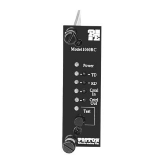
5.0 OPERATION Once you have configured each Model 1060RC and connected the cables, you are ready to operate the units. Section 5.0 describes the LED status monitors, the power-up procedure and the use of the built-in loopback test modes. 5.1 LED STATUS MONITORS The Model 1060RC features ten front panel status LEDs that indicate the condition of the modem and communication link. - Page 18 1060RC when its card-edge connector makes contact with the chassis' mid-plane socket, or when the chassis' power supply is turned on. Note: The 1060RC is a "hot swappable" card—it will not be damaged by plugging it in or removing it while the rack is powered up.
-
Page 19: Test Modes
Remote Analog Loop The Remote Analog Loop test mode causes any characters sent from the remote 1060RC to the local 1060RC to be returned back to the remote device (see figure 13 on the following page). Note: Only the local 1060RC should be in "test" mode. The remote 1060RC should be in "normal"... -
Page 20: Appendix Aspecifications
Power Supply: Rack-mount power supply is switchable between 120V and 240V AC; rack chassis supplies 10V AC to the Model 1060RC, typical Model 1060RC consumption is 700 mW Fuse: 400 mA for 120V applications; 200 mA for 240V applications Temperature: 0-50 C / 32-122 °... - Page 21 APPENDIX B CABLE RECOMMENDATIONS The Patton Model 1060RC operates at frequencies of 100kHz or less and has been performance tested by Patton technicians using twisted-pair cable with the following characteristics: Wire Gauge Capacitance Resistance 19 AWG 83nf/mi or 15.72 pf/ft.
- Page 22 APPENDIX C FACTORY REPLACEMENT PARTS The Patton Model 1060RC rack system features interchangeable rear half cards, power cords/fuses for international various operating environments and other user-replaceable parts. Model numbers and descriptions for these parts are listed below: Patton Model # Description 1000RPEM......120/240V Rear Power Entry Module...
- Page 23 Request to Send / Ready for Receiving PATTON MODIFIED MODULAR INTERFACE - 10 Wire RJ-45 Contact Number Circuit Description Receive Clock (Not Used for 1060RC) Ring Indicator or DSR Received Line Signal Indicator 108 / 2 DTE Ready Signal Common...
- Page 24 APPENDIX E BLOCK DIAGRAM...
- Page 28 Dear Valued Customer, Thank you for purchasing Patton Electronics products! We do appreciate your business. I trust that you find this user manual helpful. We manufacture one of the widest selections of data communications products in the world including CSU/DSU's, network termination units, powered and self-powered short range modems, fiber optic modems, interface converters, baluns, electronic data switches, data-line surge protectors, multiplexers, transceivers, hubs, print servers and much more.
Need help?
Do you have a question about the 1060RC and is the answer not in the manual?
Questions and answers