Table of Contents

Related Manuals for Patton electronics 1186RC


Summary of Contents for Patton electronics 1186RC
- Page 1 USER MANUAL MODEL 1186RC G.703/G.704 to Multi-mode Fiber Rack Mount Modem Card Part# 07M1186RC-A SALES OFFICE Doc# 017171UA (301)975-1000 Revised 12/01/00 TECHNICAL SUPPORT (301)975-1007 An ISO-9001 http://www.patton.com Certified Company...
-
Page 2: Table Of Contents
However, there is no guarantee that interfer- 4.3.1 Universal AC Power (100-240VAC) ence will not occur in a particular installation. If the Model 1186RC 4.3.2 DC Power does cause interference to radio or television reception, which can be 5.0 Operation ................13... -
Page 3: Service
Figure 1. Network extension remote location The Model 1186RC is designed to transmit/receive G.703/G.704 data over one string of fiber. The Model 1186RC allows transmission over Multi- Mode fiber with distances up to 2.5 km (1.5 miles). The clocking options for the Model 1186RC include Internal, Network (from G.703/G.704... -
Page 4: Configuration
Note: The Model 1186RC units are intended to work in pairs. When set- ting the clock modes for the Model 1186RC units, one end of the link Figure 3 shows the orientation of the DIP switches in the “ON” and must be set for Receive Recover and the other end must be set for either “OFF”... -
Page 5: Configure The Rear Interface Card
1001RCM703ST (with ST fiber connector) and 1001RCM703SMA (with SMA fiber connector). See Figure 4, at upper right. Each of these inter- Figure 5: Top view of 1186RC circuit board and location of jumpers face cards support one fiber connector, two BNC and one RJ-48C line connectors. -
Page 6: Installation
4.1.2 Installing Model 1186RC Series Into the Rack Chassis The Model 1186RC Series is comprised of a front card and a rear card. The two cards meet inside the rack chassis and plug into each other by way of mating 50 pin card edge connectors. Use the following... -
Page 7: Connect The G.703/G.704 Network
The fiber connects to the rear interface card using either an ST or an SMA connector. The rear interface card for the Model 1186RC is equipped with a single RJ-48C jack option for connections to a G.703/G.704 Network. If Figure 9 below shows a close-up of both connector types. -
Page 8: Operation
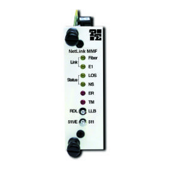
Network and a local connection. Any data sent to the local Model 1186RC in this test mode will be echoed (returned) back to the user (see Figure 11). If two Model... - Page 9 Loopbacks, turn on one of the loopbacks, and follow these instructions: 1. Locate the "511/511E" toggle switch on the front panel of the Model 1186RC and move it UP. This activates the V.52 BER test mode and transmits a "511" test pattern into the loop. If any errors are present, the local modem's red "ER"...
-
Page 10: Operation
APPENDIX A APPENDIX A G.703/G.704 Specific Interface: Female Dual Coaxial 75 ohm or PATTON ELECTRONICS MULTI-MODE FIBER RACK MOUNT Female RJ-48C 120 ohm MODEM WITH G.703/G.704 INTERFACE Line rate: 2.048 Mbps SPECIFICATIONS Line coding: AMI or HDB3 (HDB3 is the default) Isolation: 1500 Vrms Clocking Modes:... -
Page 11: Appendix B - Factory Replacement Parts And Accessories
AND ACCESSORIES Patton Electronics Model # Description 1186 ........multi-mode fiber optic modem 1186RC........multi-mode fiber rack card modem 1001RCM703ST ....interface card with ST fiber connector 1001RCM703SMA ....interface card with SMA fiber connector 1001RPEM-RAC ....120/240V Rear Power Entry Module 1001RPSM-RUI....120/240V Front Power Supply Module 1001RPEM-RDC....DC Rear Power Entry Module...
Need help?
Do you have a question about the 1186RC and is the answer not in the manual?
Questions and answers