Table of Contents
Advertisement
Quick Links
Advertisement
Table of Contents

Related Manuals for Patton electronics 1206RC


Summary of Contents for Patton electronics 1206RC
- Page 1 USER MANUAL MODEL 1206RC Synchronous X.21 Modem Eliminator: Rack Mount Card SALES OFFICE Part# 07M1206RC-C Doc# 049061U, (301) 975-1000 Rev. D TECHNICAL SUPPORT Revised 1/22/08 (301) 975-1007 An ISO-9001 http://www.patton.com Certified Company...
-
Page 2: Radio And Tv Interference
The Model 1206RC has been tested and found to comply with the limits for a Class A computing device in accordance... - Page 3 Technical Service at (301) 975-1007. Packages received without an RMA number will not be accepted. Patton Electronics’ technical staff is also available to answer any questions that might arise concerning the installation or use of your Model 1206RC. Technical Service hours: 8AM to 5PM EST, Monday through Friday.
-
Page 4: General Information
300 feet, and all necessary data, clocking and control signals are supported. The Model 1206RC is designed to mount in Patton’s 2U high, 16- slot rack chassis, as well as Patton’s 2/4/8-slot desktop Cluster Boxes. - Page 5 3.1 FUNCTION CARD CONFIGURATION All switches and jumpers are located on the Model 1206RC’s PC board. To access the PC board, loosen the two thumb screws on the front panel and slide the card out of the chassis. As Figure 1 (below) illustrates, the DIP switches are located on the “daughterboard”...
- Page 6 128 kbps 144 kbps 3.3 FUNCTION CARD JUMPERS The Model 1206RC has two ports (Port A and Port B), which must be configured independently for clocking. As Figure 3 (below) shows, each configuration jumper has three possible positions: strap covering posts 1 &...
- Page 7 Figure 4 (below) shows the location of jumpers JP4 and JP5 on the Model 1206RC front card. Figure 4. Jumper locations on Model 1206RC front card JP5: Clock Source (Port A) The setting for jumper JP5 determines–with respect to Port A–...
-
Page 8: Rear Card Configuration
3.4 REAR CARD CONFIGURATION The rear interface card for the Model 1206RC is equipped with two female UD-26 connectors: one for each DTE host port. This card has one configuration jumper (JB4). Figure 5 (below) shows the location of this jumper on the PC board. -
Page 9: Installation
4.0 INSTALLATION This section describes the functions of the Model 1000R16 rack chassis, tells how to install front and rear Model 1206RC cards into the chassis, and provides diagrams for wiring the interface connections correctly. 4.1 THE MODEL 1000R16 RACK CHASSIS The Model 1000R16 Rack Chassis (Figure 6) has sixteen card slots, plus its own power supply. - Page 10 4.2 INSTALLING THE MODEL 1206RC INTO THE CHASSIS The Model 1206RC is comprised of a front card and a rear card. The two cards meet inside the rack chassis and plug into each other by way of mating 50 pin card edge connectors. Use the following steps as...
- Page 11 Port A and Port B, as discussed in Section 3.0. A1 B1 Figure 7. Model 1206RC rear interface card, showing connectors To connect X.21 host (DTE) devices A and B to the Model 1206RC, follow these instructions: 1. Configure the Model 1206RC for your specific application according to the instructions in Section 3.0 of this manual.
-
Page 12: Operation
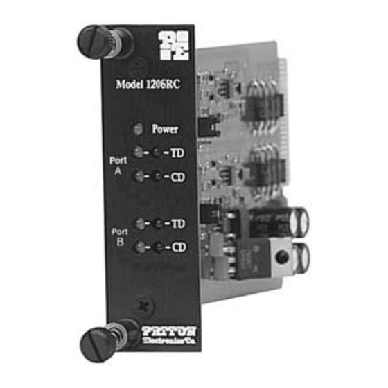
5.1 LED STATUS MONITORS The Model 1206RC features 9 front panel status LEDs that indicate the condition of the Model 1206RC and the two ports, A & B (see Figure 9, above): Figure 9. Model 1206RC front panel, showing LED indicators. - Page 13 1206RC when its card-edge connector makes contact with the chassis’ mid-plane socket, or when the chassis’ power supply is turned on. Note: The 1206RC is a “hot swappable” card—it will not be damaged by plugging it in or removing it while the rack is powered up.
- Page 14 TD and CD; common “Power” indicator Power Supply: Rack-mount power supply is switchable between 120V and 240V AC; chassis supplies 10V AC to the Model 1206RC, typical consumption is 700mW Temperature: 0-50°C / 32-122°F Humidity: 5 to 95%, noncondensing Dimensions: 0.95”w x 3.1”h x 5.4”l...
-
Page 15: Factory Replacement Parts
APPENDIX B FACTORY REPLACEMENT PARTS The Patton Model 1206RC rack system features interchangeable rear cards, power cords for international various operating environments and other user-replaceable parts. Model numbers, descriptions and prices for these parts are listed below: Patton Model # Description 1000RPEM......120/240V Rear Power Entry Module... - Page 16 APPENDIX C PATTON MODEL 1206RC INTERFACE STANDARDS MODEL 1206RC X.21 INTERFACE (DCE WIRING) Not Used -26 13- Not Used Not Used -25 12- (TC/) Transmit Clock Network Clock (XTC) -24 11- (XTC/) Network Clock Not Used -23 10- (CD/) Carrier Detect...
- Page 17 Notes __________________________________________ __________________________________________ __________________________________________ __________________________________________ __________________________________________ __________________________________________ __________________________________________ __________________________________________ __________________________________________ __________________________________________ __________________________________________ __________________________________________ __________________________________________ __________________________________________ __________________________________________ __________________________________________...
- Page 18 Notes __________________________________________ __________________________________________ __________________________________________ __________________________________________ __________________________________________ __________________________________________ __________________________________________ __________________________________________ __________________________________________ __________________________________________ __________________________________________ __________________________________________ __________________________________________ __________________________________________ __________________________________________ __________________________________________...
- Page 19 Notes __________________________________________ __________________________________________ __________________________________________ __________________________________________ __________________________________________ __________________________________________ __________________________________________ __________________________________________ __________________________________________ __________________________________________ __________________________________________ __________________________________________ __________________________________________ __________________________________________ __________________________________________ __________________________________________...
- Page 20 Dear Valued Customer, Thank you for purchasing Patton Electronics products! We do appreciate your business. I trust that you find this user manual helpful. We manufacture one of the widest selections of data communications products in the world including CSU/DSU's, network termination units, powered and self-powered short range modems, fiber optic modems, interface converters, baluns, electronic data switches, data-line surge protectors, multiplexers, transceivers, hubs, print servers and much more.
Need help?
Do you have a question about the 1206RC and is the answer not in the manual?
Questions and answers