Advertisement
Quick Links
TECHNICAL
TECHNICAL
T
T
E
L
E
E
L
E
F
e
a
t
u
r
e
s
F
e
a
t
u
r
e
s
• Terminal strip connections for normally open,
normally closed, and common for all four
relays
• Relays can be toggled or timed closures of
from 1 - 99 seconds can be activated
• Terminal strip connections for all four sensor
inputs
• Notification by email or text message of
sensor input state change
• Ready-to-use webpage control interface
• Encrypted login
• Two levels of access based on login:
- Administrator (full access)
- Guest (programmable limits)
• Relay names and input names can be cus-
tomized on webpage
• Firmware remotely updateable
P
h
o
n
e
.
.
.
7
1
5
.
3
8
6
P
h
o
n
e
.
.
.
7
1
5
.
3
8
6
w
w
w
.
v
i
k
i
n
g
e
l
e
c
t
w
w
w
.
v
i
k
i
n
g
e
l
e
c
t
S
S
C
O
M
O
L
U
T
I
O
N
S
C
O
M
O
L
U
T
I
O
N
S
Control Relay Contacts Across
a Local Area Network
.
8
8
6
1
.
8
8
6
1
r
o
n
i
c
s
.
c
o
m
r
o
n
i
c
s
.
c
o
m
P
r
a
c
P
r
a
c
2
1
C
2
1
C
F
O
R
T
H
E
S
T
F
O
R
T
H
E
S
T
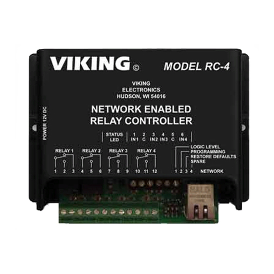
The RC-4 Network Enabled Relay Controller
provides networked control of four remote
relays via a web interface. The same interface
can be used to check the status of four contact
closures at the remote location.
Relays can be toggled on or off, or user-pro-
grammed timed closures can be activated.
Two levels of user access permit selected
users to have full operational and program-
ming rights while others have operational con-
trol but not programming capability.
A
p
p
l
i
A
p
p
l
Remote Control of:
• Secure building entry
• Heating/cooling equipment
• Pumps and fans
• Security system
• Gates
• Lighting
• Emergency tones
S
p
e
c
S
p
e
c
Power: 120VAC/12VDC 500ma UL listed adapter provided
Dimensions: 133mm x 89mm x 44mm (5.25" x 3.5" x 1.75")
Shipping Weight: .9 kg (2 lbs)
Environmental: 0 C to 32 C (32 F to 90 F) with 5% to 95% non-
condensing humidity
Relay Contact Ratings: 5A @ 30VDC/250VAC
Connections: (1) 12 position screw terminal block, (1) 6 posi-
tion elevated screw terminal block
LAN Interface: (1) RJ45 10Base-T
Minimum Requirements: Windows XP and up, Java-script
enabled internet browser
RC-4
RC-4
Network Enabled
t
i
c
e
t
i
c
e
Relay Controller
September 19, 2012
E
N
T
U
R
Y
E
N
T
U
R
Y
c
a
t
i
o
n
s
i
c
a
t
i
o
n
s
i
f
i
c
a
t
i
o
n
s
i
f
i
c
a
t
i
o
n
s
Advertisement

Related Manuals for Viking RC-4


Summary of Contents for Viking RC-4
- Page 1 September 19, 2012 Control Relay Contacts Across a Local Area Network The RC-4 Network Enabled Relay Controller provides networked control of four remote relays via a web interface. The same interface can be used to check the status of four contact closures at the remote location.
- Page 2 Viking Electronics, Inc., 1531 Industrial Street, Hudson, WI 54016 (715) 386-8666...
- Page 3 It resides in the device’s memory and is used by routers to send network traffic to the cor- rect IP address. You can find the MAC address of your RC-4 printed on a white label on the top surface of one of the relays.
- Page 4 B. Setting Up the RC-4 on the Network The RC-4 is controlled by a webpage that is accessed using a web browser. To connect to the page, it is necessary to know either the IP address of the RC-4, which is the address that was assigned by the network server when the RC-4 powered up, or to know the host name of the RC-4.
-
Page 5: Dip Switch Programming
To return to defaults, the RC-4 must be powered down. With the unit powered down, turn on Dipswitch 3. Power up the RC-4. After four to eight seconds, the Status LED starts flashing. Turn Dipswitch 3 back off. After a second or two the status LED returns to steady on, and the return to defaults procedure is complete. - Page 6 Near the top of the page, locate and click on “Click here for access”. The browser’s authentication dialog appears. For User Name, enter “admin”, and for Password, enter “viking”. The main page appears. Note that all four remote switch- es are shown Open and the relays are all Off.
- Page 7 The relays may be toggled On or Off, or they may be programmed to provide a timed closure of from 1 to 99 seconds. Relay 1 is red, which indicates that it is Off. Click on the image of the red circle next to “Relay 1”. The circle changes from red to green, and relay 1 is turned on.
-
Page 8: Settings Page
The RC-4 also provides a status indication for the four inputs on the terminal block. In the pictures, inputs 1 and 3 are shown as Open and inputs 2 and 4 are shown as Closed. This indication is constantly refreshed so that the status indication is always current. - Page 9 In the event that secure login is not required, the RC-4 can be programmed to skip the authentication step and go directly from the “Click here for access” page to the main page. To do this, go to the RC-4 Settings page and locate the Usernames and Passwords section near the bottom.
- Page 10 Host Name (Unit Name): The current host name appears in this box. The default host name, MYVIKING, can be changed to pro- vide a more user-specific name or to distinguish between multiple RC-4’s installed on the same network. The host name can be 1 –...
-
Page 11: Email Notification
At the bottom of the Settings page, click on Email Notification. The Email Notification page appears. This page is for setting up email notification of input events. The RC-4 can be programmed to send an email if one of the inputs closes, and also if it opens. -
Page 12: Text Message Notification
Call 715-386-8666 M-F 8:00 AM to 5:00 PM CST Due to the dynamic nature of the product design, the information contained in this document is subject to change without notice. Viking Electronics, and its affiliates and/or subsidiaries assume no responsibility for errors and omissions contained in this information. Revisions of this document or new editions of it may be issued to incorporate such changes.
Need help?
Do you have a question about the RC-4 and is the answer not in the manual?
Questions and answers