Table of Contents
Advertisement
Quick Links
INPUT A
PHONES
INPUT B
BAL
BAL
GUITAR
GUITAR
LINE
MIC
LINE
MIC
MIN
UNBAL
TRIM
UNBAL
TRIM
CH ON/OFF
CH ON/OFF
PEAK
PEAK
TRACK STATUS
RED
REC
GREEN
TRACK STATUS / TRACK SEL
1
2
3
4
+6
+6
+6
+6
+6
0
0
0
0
0
-10
-10
-10
-10
-10
-20
-20
-20
-20
-20
-30
-30
-30
-30
-30
-40
-40
-40
-40
-40
-
-
-
-
-
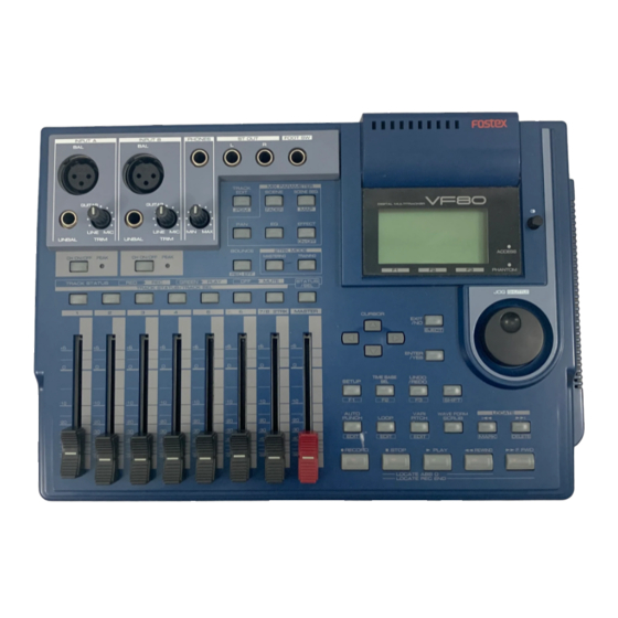
Owner's Manual
Digital Multitracker
ST OUT
FOOT SW
L
R
MIX PARAMETER
TRACK
EDIT
SCENE
SCENE SEQ.
PGM
FADER
MAP
PAN
EQ
EFFECT
MAX
ON/OFF
2TRK MODE
BOUNCE
MASTERING
TRAINING
REC EFF
PLAY
OFF
MUTE
STATUS
/SEL
5
6
7/8 2TRK
MASTER
+6
+6
+6
0
0
0
-10
-10
-10
-20
-20
-20
-30
-30
-30
-40
-40
-40
-
-
-
DIGITAL MULTITRACKER
F1
F2
F3
CURSOR
EXIT
/NO
EJECT
ENTER
/YES
TIMEBASE
UNDO
SETUP
SEL
/REDO
F1
F2
F3
SHIFT
WAVE FORM
AUTO
VARI
PUNCH
LOOP
PITCH
SCRUB
EDIT
EDIT
EDIT
MARK
RECORD
STOP
PLAY
REWIND
LOCATE ABS 0
LOCATE REC END
8588 011 000
(356698)
ACCESS
PHANTOM
JOG
SHUTTLE
LOCATE
DELETE
F FWD
Advertisement
Table of Contents

Related Manuals for Fostex VF80


Summary of Contents for Fostex VF80
- Page 1 Owner’s Manual Digital Multitracker INPUT A PHONES ST OUT INPUT B TRACK EDIT GUITAR GUITAR LINE LINE UNBAL TRIM UNBAL TRIM BOUNCE CH ON/OFF CH ON/OFF PEAK PEAK REC EFF TRACK STATUS GREEN PLAY TRACK STATUS / TRACK SEL FOOT SW MIX PARAMETER SCENE SCENE SEQ.
-
Page 2: Safety Instructions/Precautions
Safety Instructions/Precautions CAUTION RISK OF ELECTRIC SHOCK DO NOT OPEN CAUTION: TO REDUCE THE RISK OF ELECTRIC SHOCK, DO NOT REMOVE COVER (OR BACK). NO USER - SERVICEABLE PARTS INSIDE. REFER SERVICING TO QUALIFIED SERVICE PERSONNEL. "WARNING" "TO REDUCE THE RISK OF FIRE OR ELECTRIC SHOCK, DO NOT EXPOSE THIS APPLIANCE TO RAIN OR MOISTURE."... -
Page 3: Precautions
Specifications section of this owner’s manual. Do not use an AC outlet of any other voltage. • Do not connect the VF80 to the same AC outlet to which devices that could generate noise (such as a large motor... - Page 4 Please read page 68. I want to create multiple programs. Please read page 61. I want to control the VF80 via MIDI. Please read pages 91, 92, and 94. I want to make my original CD. Please read page 115.
- Page 5 Please read page 79. I want to set the MTC offset time. Please read page 127. I want to synchronize the VF80 with an external device. Please read page 91. I want to feed the MIDI sync signal to an external MIDI device.
-
Page 6: Table Of Contents
Precautions upon handling the hard disk ... 3 Note on repair ... 3 About copyright ... 3 About damage ... 3 Basic Features of VF80 • Product Features ... 9 • Before Operating ... 10 RECORDING method ... 10 Program ... 10 Remain Indicator ... - Page 7 Recording the guitar ... 85 Recording with effect ... 86 • Digital Recording ... 90 Recording an external source onto the VF80 digitally 90 Selecting a program to be recorded ... 90 Selecting the digital input ... 90 Selecting a track to record ... 90 Starting to record ...
- Page 8 Contents Save/Load of Song Data • About Song Data ... 96 Items that can be saved or loaded as song data ... 97 • Save/load using the S/PDIF digital signal ... 97 Notes for digital audio recorder to be used ... 97 Notes for saving data using the S/P DIF digital signal 97 Saving data using the S/P DIF digital signal ...
-
Page 9: Basic Features Of Vf80
Basic Features of VF80 The VF80 Digital Multitracker incorporates a digital mixer with an 8-track (plus 16-additional track) digital recorder. The digital mixer section features a high-performance DSP multi-effect processor employing the A.S.P. (Fostex Advanced Signal Processing) technology originally developed by Fostex. The digital recorder section allows you to record and playback uncompressed linear 16-bit/44.1 kHz digital audio. -
Page 10: Before Operating
Basic Features of VF80 This section describes the basics that you should know before you start operating the VF80. All users, including those who are familiar with using tape-based Multitracker and those who are new to Multitracker, should read this section thoroughly to understand the functions of the VF80. -
Page 11: Additional Track
These files (audio files and silent files) are called "events". With the VF80, you can create up to 512 events per track. You cannot make any further recording when 512 events are created. In the normal use, 512 events are enough. -
Page 12: Trim
ABS 0 is the reference position for managing all the location and related to other time bases. Bar/Beat/Clk shows the musical position generated from the internal tempo map of the VF80 (including time signature and tempo). The example below shows the current recorder posi- tion is at beat 1 of bar -2. -
Page 13: Top Panel
Names and Functions INPUT A PHONES INPUT B GUITAR GUITAR LINE LINE UNBAL TRIM UNBAL TRIM CH ON/OFF CH ON/OFF PEAK PEAK TRACK STATUS GREEN PLAY TRACK STATUS / TRACK SEL POWER Top panel ST OUT FOOT SW MIX PARAMETER TRACK EDIT SCENE... -
Page 14: Top Panel (Analog Input/Output Section)
Names and functions Top panel (Analog input/output section) INPUT A GUITAR LINE UNBAL TRIM UNBAL CH ON/OFF CH ON/OFF PEAK TRACK STATUS 1. [INPUT A/UNBAL] (Unbalanced) connector • Connects to the unbalanced output of an external sound source. • Reference input level: -50 dBV to +2 dBV •... -
Page 15: Top Panel (Mixer Section)
10. [FOOT SW] (Foot switch) connector • Connects to an optional foot switch (Model 8051) for punch in/out operation. • Connector type: phone jack <Caution> Do not power on the machine with non-specified foot SW connected to the foot SW jack. When powering on the machine with non-specified foot SW (latch type foot SW, etc.) connected to the foot SW jack, there is a case that the machine does not correctly boot up with “No... -
Page 16: Top Panel (Recorder/Display Section)
Names and functions 16. [MIX PARAMETER-EQ] key • When viewing or editing the EQ setting, press this key. • Select the track to be viewed or edited by pressing the corresponding [TRACK STATUS/TRACK SEL] key. 17. [MIX PARAMETER-SCENE / FADER] key •... - Page 17 • Lights up while the internal hard disk drive or external backup SCSI device is writing or reading data. <Caution> Do not turn off the VF80 power while this indicator lights. Data recorded in the disk may be erased. 30. [PHANTOM] indicator •...
- Page 18 Names and functions 42. [WAVE FORM SCRUB] key • Pressing this key enters the scrub mode. In the scrub mode, you can scrub audio forward or backward digitally. 43. [VARI PITCH / EDIT] key • Pressing this key switches between On and Off of the vari pitch (vari-speed playback/recording) function.
-
Page 19: Rear Panel
(S/P DIF) digital input of an external digital device. If the external device only provides the optical digital input, use the Fostex COP-1 coaxial/optical converter. • Connector: RCA pin jack 56. Slot for the optional CD-RW drive • You can install the Model CD-1A optional CD-RW drive in this slot. -
Page 20: About The Hard Disk Storage Device
About the hard disk storage device The VF80 is complete with a 3.5-inch E-IDE hard disk (storage device) which is formatted in the Master 8 mode. Therefore, there is no need to newly assemble a hard disk or to format the hard disk. -
Page 21: Replacing A Hard Disk
<Precautions Upon Replacement> • Always turn OFF the power of the VF80 and unplug the power plug from the electric outlet when replacing the hard disk. - Page 22 About the hard disk storage device Unscrew the four screws from the bottom of the main unit that are fixing the panel. Turn over the panel that the hard disk is fixed according to the instructions shown in the figure below. Note that hard disk cables will be connected.
-
Page 23: Formatting The New Hard Disk
Formatting the Hard disk Carefully follow the instructions below to newly format the hard disk properly. Turn ON the VF80 after plugging the power cable in the electric outlet. The VF80 will startup. “Unformat!” will appear on the LCD. The menu will automatically go to the SETUP mode. -
Page 24: Basic Recording And Playback
“Preliminary knowledge” and “LCD”. About a demonstration song! Your VF80 may have a demonstration song on program 1 (P01) when shipped (note that some VF80 units may not have a demonstration song, depending on the production). Please check whether a demonstration song is recorded or not on your unit according the following manner. -
Page 25: Connections Of External Equipment
You can connect various sound sources and external devices to the input and output connectors of the VF80 as shown in the example below. When making connection, make sure that the [MASTER] fader is set to the lowest (“ ”) position and the [PHONES] knob to the left most (“MIN”) position. Otherwise, your speakers or headphones may damage by the audio noise generated when connecting cables. -
Page 26: Lcd
This section describes major contents on the LCD display and their operations. Display when turning on the power When turning on the power of the VF80 on which a formatted hard disk is installed, the unit starts up and “Initial..” and “version number” appears on the LCD display, followed by “Current Dr”, “IDE”, “hard disk name... -
Page 27: Preliminary Knowledge
• Be sure to keep the following notes. * When connecting a condenser microphone to the balanced input connector of the VF80, check whether or not the microphone needs the phantom power (+48 V). * Switch the [PHANTOM] switch to ON after connecting a microphone. -
Page 28: Basic Recording (Recording Onto A Single Track)
Basic recording (recording onto a single track) At first, let’s record a single sound source onto a single track to know the basic recording procedure of the VF80 There are 8 recording tracks (Tracks 1 through 8) and you can record onto any desired track(s). -
Page 29: Recording
Press the [PLAY] key while holding down the [RECORD] key to start recording. The [TRACK STATUS/TRACK SEL] key of Track 1 and the [RECORD] key light on, showing the VF80 is now record- ing. The VF80 uses the direct recording method. In this... -
Page 30: Basic Recording (Recording Onto Two Track)
Basic Recording/Playback Basic recording (recording onto two tracks) After recording onto track 1 as described in the previous section, let’s make recording of a stereo sound source onto tracks 3 and 4. Stereo source INPUT A GUITAR LINE UNBAL TRIM UNBAL CH ON/OFF CH ON/OFF... -
Page 31: Recording
The [TRACK STATUS/TRACK SEL] keys of Tracks 3 and 4, as well as the [RECORD] key light on, showing the VF80 is now recording. You can see the meter for Track 1 also moving. By rais- ing the Track 1 fader, you can make overdubbing onto tracks 3 and 4 while listening to playback of track 1. -
Page 32: Mark Function
Mark function The VF80 has the Mark function which allows you to set marks at the desired positions in a song. You can locate a mark position immediately, as well as use mark positions for the punch in and out points, beginning and end points for repeat and editing points for track editing such as copy, move, erase, etc. -
Page 33: Abs Locate
ABS locate functions There are four types of the ABS locate functions as below. • Pressing the [REWIND] key while holding down the [STOP] key locates the beginning of the current program (ABS 00), regardless of the time base setting. •... -
Page 34: Auto Punch In/Out Function
Basic Recording/Playback Auto punch in/out function You must set the punch in and out points before per- forming auto punch in/out recording. You can set the points either during playback and while stopped. In the following description, we assume that the “ABS” time base is selected. •... - Page 35 • Taking a mark point in the punch in or punch out point You can take a mark point in the punch in or out point. <Note> The following operation is possible only when any marks are stored using the Mark function described earlier. Press the [AUTO PUNCH/EDIT] key while holding down the [SHIFT] key.
-
Page 36: Mixing
Basic Recording/Playback Mixing After recording all tracks (1 through 8), you can tailor the sound of each track. The following describes about settings for level, pan, EQ and effects. Adjusting levels Adjust the playback level of each track using the cor- responding fader (1 through 6 and 7/8). -
Page 37: Setting Effects
To set the effect send levels for other tracks, carry out step 2 and 3 above repeatedly. Effect type setting The VF80 provides 38 effect types (L01 through L38) used for the loop effect and 6 effect types (L39 through L44) used for the insert effect. -
Page 38: Mixdown
After tailoring sound of all the tracks, let’s make a master tape (disc) using your master recorder (cassette, DAT, MD, etc.). As the VF80 can feed the stereo outputs (L and R) via the S/PDIF (coaxial) digital output jack, you can make the master tape (disc) in digital domain if your recorder provides a digital input jack. -
Page 39: Mixer Functions
Initial condition when turning on the power When turning on the power, the VF80 starts up while showing the unit information on the LCD display and then gets ready when the screen below appears. This screen is called "Normal Screen", in which the program number and current recorder position are shown. -
Page 40: Mix Parameter Edit
The Mix parameter section provides five keys that are used for mixer function settings. By pressing one of these keys alone or while holding down the [SHIFT] key, you can execute the following. <Note> The VF80 mixer channels always receive corresponding track signals. They do not receive input signals. •Pan setting •EQ setting •Effect send level setting... -
Page 41: Editing Eq
The VF80 is equipped with 2-band (HI and LO) EQ for Tracks 1 through 6. 36 preset entries are available in the EQ library. <Note> You can apply EQ only to Tracks 1 through 6. You cannot apply EQ to Tracks 7/8. -
Page 42: Preset Entries In The Eq Library
Mixer Functions Preset entries in the EQ library L00: 2-SHLV Gain Flat setting Freq. The first time you bring up the EQ screen, this entry is selected. L01: LightKick Gain Creates a light and jaunty kick Freq. sound L02: TightKick Gain Creates a tight and hard kick sound. - Page 43 L20: Clean_EG Gain Adds a bright character to a trans- Freq. parent and clean electric guitar sound. L21: CrunCh_EG Gain Makes a moderately distorted Freq. crunch electric guitar sound distinc- tive. L22: OverDrvEG Gain Makes a mellow overdriven electric Freq. guitar sound fatter.
-
Page 44: Setting Effects
Mixer Functions The VF80 provides 38 digital effect types used for the loop effect and 6 types used for the insert effect. As you can select any type and adjust parameter settings for each type, comprehensive effect pro- cessing is possible. -
Page 45: How To Make The Loop Effect Setting
Delay. How to make the loop effect setting There are two methods for using the internal effect processor of the VF80; "loop effect" and "insert effect". The loop effect allows you to apply a desired effect to track signals during track bounce (ping-pong) operation to the other tracks or mixdown operation to an external master recorder. -
Page 46: Setting Effect Send Levels
Mixer Functions <Hint> When editing the loop effect setting, pressing the [EFFECT] key after turning on the power cycles the screen between "Effect send level setting screen", "Effect type/parameter setting screen" and "Effect send pre/post setting screen", as shown right. <Note>... -
Page 47: Selecting An Effect Type
] key to select a parameter to be edited, and then use the [JOG] dial to select a value. After completing the settings, press the [EXIT/NO] key. The VF80 exits the edit mode and the LCD display re- turns to the Normal screen. Selecting Pre/Post of the effect send You can select the send signals from Tracks 1 through 6 pre- or post- fader. -
Page 48: Turning The Effect Processor On Or Off
Mixer Functions Turning the effect processor on or off You can select the on or off of the effect processor. • To turn on the effect processor Press the [EFFECT/ON/OFF] key while holding down the [SHIFT] key to illuminate the [EFFECT/ON/OFF] key. The effect processor is turned on and you can hear "wet"... -
Page 49: About The Effect Types
About the effect types Effect types L01 through L38 are used for the loop effect, while L39 through L44 are used for the insert effect. Name Parameter type L01 Norm HALL REVERB L02 Pres HALL REVERB L03 Wet HALL REVERB L04 NoER HALL REVERB L05 Lo-F HALL... -
Page 50: Effect Parameter Details
Mixer Functions Effect parameter details The parameters that can be adjusted will depend on the parameter type. The following describes parameters for effect types L01 through L38 used for the loop effect. See "Advanced Operations" on page 83 for details about parameters for effect types L39 through L44 used for the insert effect. - Page 51 Chorus effect parameters (parameter type: CHORUS) For effect type 35 of the preceding "Effect type" table, the following five parameters can be adjusted. 1. Eff Level Adjust the effect return level: 0~99 2. Depth Adjust the chorus depth. Range: 0--99 3.
-
Page 52: Scene Memory
Mixer Functions The VF80 provides 100 Scene memories (S00 to S99) for each program. You can store a set of desired parameter settings to each memory. Items to be stored include all parameters set by mix parameter editing functions, as well as all track fader levels. -
Page 53: Deleting A Scene
Use the [JOG] dial to select the desired scene number to be recalled. Press the [SETUP/F1] key while holding down the [SHIFT] key. The selected scene is recalled and the display changes to the Normal display. Deleting a scene You can delete an unnecessary Scene or Temporary memory by using the following procedure. -
Page 54: Scene Sequence
Mixer Functions Using the scene sequence function, you can recall desired scene memories at the desired mark positions during playback. For example, you can recall scene memory 02 at "Bar 17/Beat 1" and scene memory 04 at "Bar 25/Beat 1", etc. To execute the scene sequence function, you must first assign scene (or temporary) memories to marks in the mark map. -
Page 55: Deleting A Mark From The Mark Map
While the VF80 is stopped, press the [SCENE SEQ] key. The [SCENE SEQ] key lights in green, showing that the scene sequence function is active (ON). -
Page 56: Recorder Functions
• As long as holding down the [SHIFT] key, shuttle cueing continues even if you release the [JOG/SHUTTLE] dial. The VF80 is "cueing" in the forward direction at 64x the normal speed. The VF80 is "cueing" in the backward direction at 64x the normal speed. -
Page 57: Digital Scrubbing
Performing digital scrubbing While stopped, press the [WAVE FORM SCRUB] key. The VF80 enters the scrub mode, and the display shows the screen below. Press the [TRACK STATUS/TRACK SEL] key for the track you are going to scrub. -
Page 58: Variable Pitch
Recorder Functions You can alter the playback or recording speed of the recorder within +/- 6.0 % range in 0.1 % increments/dec- rements by using the vari pitch function. With the vari pitch function, the pitch changes according to the speed. INPUT A GUITAR LINE... -
Page 59: Loop Function
Using the loop function, you can repeat the desired part between the Start and End points. By using the loop function together with the punch in/out or training mode, you can concentrate on playing without the need for operating the VF80. <Loop Function>... -
Page 60: Setting The Start And End Points By Marks
Recorder Functions To edit the Start point, press the [ENTER/YES] key while "Start Point" value is highlighted. The "seconds" value flashes, showing that it can be ed- ited. The "seconds" value flashes. Use the [CURSOR / ] keys to move the flashing value, and use the [JOG] dial to edit the value. -
Page 61: Program
The VF80 can have up to 99 programs (P01 through P99) and usually each program manages one song. You can make recording against each program or playback materials recorded on each program. This section describe program-related operations. Creating a new program When formatting a hard disk, a program (P01) is au- tomatically created. -
Page 62: Selecting A Program
Recorder Functions Selecting a program When more than one program exists on the disk, you have to select the desired program before starting operations for recording, playback or editing. Select the desired program by following the procedure below while the recorder is stopped and the display shows the Normal screen. -
Page 63: Track Editing
[JOG] dial (or [CURSOR keys) to select a character for the flashing point. Because the VF80 uses a 3.5-inch E-IDE hard disk as the recording media, you can make non-linear and non- destructive audio editing by track effectively. -
Page 64: Performing Copy (Or Move) Paste
Recorder Functions Performing Copy (or Move) & Paste Set the Start and End points for the copy (or move) operation and To point for the paste operation. Using the digital scrub function, set the Start, End and To points. See "Storing the digital scrub point" for details about how to set the points. -
Page 65: Undo/Redo Of Copy (Or Move) Paste
3. Letting the recorder run in playback (or recording) mode and pass through the auto punch-in point while the auto punch mode is active 4. Turning off the power of the VF80 5. Performing any of the program operations (select, rename or delete). -
Page 66: Erasing Track Data
Recorder Functions Erasing track data You can erase a desired part of track data. You can select a track or tracks (of which you are going to erase data) from among each individual track, each pair of tracks, 1-6 and 1-8. ABS 0 Erase START Point... -
Page 67: Undo/Redo Of Erase
3.Letting the recorder run in playback (or recording) mode and pass through the auto punch-in point while the auto punch mode is active 4.Turning off the power of the VF80 5.Performing any of the program operations (select, rename or delete). -
Page 68: Track Exchange
Recorder Functions Track Exchange The track exchange function allows you to exchange tracks (regardless of whether they are real or addi- tional tracks) on the program in single track unit, 2- track unit or 8-track unit. By using this function, you can exchange tracks not only among real tracks but also between real and additional tracks, allowing to use tracks effectively. -
Page 69: Editing Marks
This section describes how to edit marks, assuming that more than one mark is already stored in realtime according to the operations described in "Basic Recording and Playback". Viewing the mark list You can view the marks stored. While the recorder is stopped, press the [SCENE SEQ./ MAP] key while holding down the [SHIFT] key. -
Page 70: Enter A Mark Title
Recorder Functions Enter a mark title You can enter or edit a title for each mark. While the recorder is stopped, press the [SCENE SEQ./ MAP] key while holding down the [SHIFT] key. The Mark map screen appears. Use the [JOG] dial or [CURSOR light the desired mark, and then press the [TIME BASE SEL/F2] key. -
Page 71: Deleting A Mark
Deleting a mark You can delete an unnecessary mark. While the recorder is stopped, press the [SCENE SEQ./ MAP] key while holding down the [SHIFT] key. The Mark map screen appears. Use the [JOG] dial or [CURSOR light the mark you want to delete, and then press the [UNDO/REDO/F3] key while holding down the [SHIFT] key. -
Page 72: Advanced Operations
It also can output the metronome sound (click) according to the tempo map, allowing you to record materials at the specific tempo without the need of an external metronome or rhythm machine. The metronome sound can be output from Track 6 of the VF80 when you set "Click?" in the Setup menu to "On." <Note>... -
Page 73: Track Bounce (Ping-Pong Recording)
When the number of empty tracks is short in the recording process, you can solve the problem by transferring audio on the multiple already-recorded tracks to a different track or tracks. This operation is called "Track bounce" or "Ping-pong recording". With the VF80, you can do this operation simply by using the [BOUNCE] key. -
Page 74: Training Mode
Training mode The VF80 provides the training mode which allows you to practice your instrument while playing back only Tracks 7/8. In the training mode, you can slow down the playback speed or altering the pitch, making it easy to play along with your favorite musicians or transcribing ad-lib phrases. -
Page 75: Slowing Down The Playback Speed
Playing along with the playback sound Set the [MASTER] fader to the "0" position. Press the [PLAY] key to starts playback of the VF80 and raise the Track 7/8 fader gradually. You can see the level is going up via the stereo output level meters (L and R) on the screen. -
Page 76: Mastering Mode
Tracks 7/8. Analog master recorder Selecting a program to be played back If there is more than one program in the VF80, select the desired program to be played back. See "Selecting a program" for the operation. On/off of mastering mode Press the [MASTERING] key. -
Page 77: Setting The Mastering Effects
You have to adjust the recording level now. When the recording signal is digitally transferred from the VF80 to the recorder, because a digital recorder usu- ally does not provide the function for controlling the digital input level, you must adjust the recording level by controlling the stereo output level of the VF80 us- ing the [MASTER] fader. - Page 78 Advanced Operations L2: Light Mix Gain Freq. (fixed) Q (fixed) EQ Lo 400Hz 1kHz EQ Mid EQ Hi +4.0 8kHz Ambience 0 (Rev Level) Rev Time=1.0s / Pre Dly=0ms : fixed Comp THSHD 3 : 1 Comp Ratio Comp Gain Atack Time = 10ms : fixed L3: Live Mix Gain Freq.
-
Page 79: Please Read
Internal Mastering Function The internal mastering function is an expansion of the mastering function described earlier. It allows you to record a mixed-down material on tracks 7 and 8 to the current drive on the VF80 while applying a mastering effect. -
Page 80: Rehearsing Internal Mastering
[ENTER/YES] key. Set the [MASTER] fader to the "0" position. Press the [MASTERING] key. The VF80 enters the mastering mode and the display shows the mastering screen in which you can adjust the mastering effects. The [MASTERING] key lights up in red, while the [TRACK STATUS/TRACK SEL] keys of tracks 7/8 and the master channel light up in green. -
Page 81: Please Read
When recording a take in the internal mastering func- tion according to the following procedure, the VF80 au- tomatically arms Tracks 1 and 2. Therefore, the [TRACK STATUS/TRACK SEL] keys for tracks 1 and 2 never light up in red during recording. -
Page 82: About Start And End Points
This function is very convenient for making an audio CD from mastered materials, because data between "Start point" and "End point" is automatically transferred to a CD-RW/CD-R disc. Note that you cannot make an audio CD using the VF80 save function (described later) without setting these two points. -
Page 83: Using The Insert Effect
Using the insert effect Unlike the loop effect described earlier in "Mixer Functions", the insert effect is applied when rerecording any recorded track among tracks 1 through 6. This rerecording mode in which the insert effect is applied is called "REC EFFECT" mode. Six distortion/simulation type effects are available for the insert effect. -
Page 84: Rehearsal
Before executing recording, you can check the guitar sound with the distortion effect while rehearsing the effect parameter settings until you satisfy with the sound. We assume that the guitar is connected to the [INPUT A] connector and the VF80 locates to the beginning of the program (ABS 0). -
Page 85: Recording The Guitar
<How to edit parameters> The "L39: Gtr Dist" effect type has 11 parameters as shown below. (Note that the screen example below shows all parameters for the explanation. Actually, you can see 5 parameters at a time while the other parameters are hidden.) Use the [CURSOR] keys to select a highlighted... -
Page 86: Recording With Effect
Advanced Operations Rerecording with effect The final step is to rerecord the recorded "dry" sound on track 1 while applying the effect (guitar distor- tion) with the setting you made in rehearsal. Press the [BOUNCE/REC EFF] key while hold- ing down the [SHIFT] key. The unit enter the REC EFFECT mode, in which you can apply the insert effect. - Page 87 • Parameters for distortion effects (Parameter type: DISTORTION) Effect types No.39 through 42 (shown in "Effect type list" on page 49) are distortion types. Each of these has 11 parameters as shown below. Selects a distortion type. Each effect type has following distortion type options.
- Page 88 Advanced Operations • Parameters for distortion effects (Parameter type: AMP SIMULATION) Effect type No.43 (shown in "Effect type list" on page 49) is the amp simulation type. This effect type has 11 parameters as shown below. Selects an amplifier type to be simulated. Options: Brit800, TremoRect, MetalRect, 1.
- Page 89 Selects a microphone input type. Options: US Dyn 58 (dynamic type), MCon2 1. IN (condenser type) Default: US Dyn 58 Selects a microphone output type to be simu- lated. Options: TCon3k, TCon3k LC, TCon414, TCon414LC1, TCon414LC2, TDyn112, GDyn421, 2. Out GDyn421LC3, GDyn421LC2, GDyn421LC1, GDyn421SPE, MCon1, MCon2, MConV, UsDyn58, VCon47, VCon87, VCon87 LC...
-
Page 90: Digital Recording
Digital recording You can digitally record an external digital source to the VF80, or stereo output signals of the VF80 to an external digital recorder. This section describes how to make digital recording between the VF80 and an external digital device. -
Page 91: Midi Clock Sync System
MIDI clock and song position pointer according to the setting, a hardware type MIDI sequencer can be synchronized as a MIDI clock slave. Consequently, in this system, the VF80 will be the master and the MIDI sequencer the slave. -
Page 92: Setup Of The Vf80
(absolute time) and output it as MTC in any desired frame rate. It can also carry out the proper operation upon receiving an MMC from outside. In this case, because the VF80 can setup a DEVICE ID number by the SETUP mode “MIDI Device ID Setting”... -
Page 93: Connecting To External Equipment
When a correct MIDI command (MMC or FEX) is received, “MIDI” in the display will be lit for about 40msec. There is no setting in the VF80 to receive MMC but it will operate if a correct MIDI signal is input. -
Page 94: External Midi Equipment Sync System By The Slave Mode
External MIDI equipment sync system by the slave mode Up to this point, synchronization with external MIDI equipment has been explained with the VF80 as the master and MIDI equipment as the slave but depending on the slave mode setting, the MIDI equipment can be set as the master and the VF80 as the slave. -
Page 95: Executing Of Recording
<One Point Advice> Sync signal “Vari” of the “Slave mode setting” menu: When the VF80 is made to chase lock by MTC only, variable pitch will be constantly applied by external MTC. If a digital signal is output to an external digital... -
Page 96: Save/Load Of Song Data
When loading song data from the external device to the VF80 via the S/PDIF digital signal, data is transferred with two-track data blocks, as with the same way as saving data from the VF80 to the external device. (See also <Notes>... -
Page 97: Items That Can Be Saved Or Loaded As Song Data
Saving/loading data using the S/PDIF digital signal <Notes for digital audio recorders to be used> The VF80 song data only can be saved to or loaded from digital recorders that can handle 16 bit, 44.1 kHz linear digital data with S/PDIF format (such as DAT recorders). -
Page 98: Saving Data Using The S/Pdif Digital Signal
You can save data using the S/PDIF digital signal via the [S/P DIF DATA OUTPUT] (coaxial) jack. • Use an external digital recorder that supports 44.1 kHz sampling frequency (the same as the VF80, Connecting to an external digital recorder Connect the [S/P DIF DATA OUTPUT] jack to the digital input jack of the external digital recorder (DAT, etc.). - Page 99 "Wait time" starts counting down. For the first several seconds, the VF80 transmits the pilot signal that will be a reference for locating the tape position during the load operation, and the actual data saving starts from the position at which "Wait...
-
Page 100: Loading Data Using The S/P Dif Digital Signal
Loading data using the S/PDIF signal You can load data using the S/PDIF digital signal via the [S/P DIF DATA INPUT] (coaxial) jack. *Use an external recorder that supports 44.1 kHz sampling frequency (the same as the VF80). Connecting to an external recorder Connect the [S/P DIF DATA INPUT] jack to the digital output jack of the external digital recorder. - Page 101 "Sure?" flashes. <Note> In the above step, if the VF80 does not lock to the digital signal from the external digital recorder, the following warning message appears on the display, showing that the VF80 does not receive a correct S/ PDIF digital signal.
-
Page 102: Save/Load Using Cd-Rw/Cd-R
Save/Load using CD-RW/CD-R By installing the optional CD-RW drive (Model CD-1A) to the VF80, you can save or load data in the FDMS-3 or WAV file format using a CD-RW/CD-R disc. In addition, you can create an audio CD (CD- DA) or load audio data from an audio CD. - Page 103 The writing speed depends on a CD-RW drive but it is limited to 8 times. For save/load of the VF80 data, use discs that can be written at 4 times or higher speed. Do not use discs that only can be written at real-time or twice speed.
-
Page 104: Saving Data Using A Cd-Rw Drive (Backup)
Saving data using a CD-RW drive (Backup) The following procedure describes how to save FDMS-3 song data. We assume that the optional CD-RW drive (Model CD-1A) is already installed to the VF80 and a virgin CD-RW or CD-R disc is set. - Page 105 When completing the save operation, “Save Com- pleted!” appears on the display (as shown below) and the VF80 stops access to the drive, while the disc in the CD-RW drive is automatically ejected. When saving data to more than one disc, the first disc will be ejected when it is full (i.e.
- Page 106 Save/Load of Song data Flashing Increases as the process progresses. Immediately after completing erasing the disc, the display shows the same screen (for selecting a pro- gram to be saved) which appears after step 5 is performed. Hereafter, perform the same proce- dure as described above.
-
Page 107: Loading Backup Data From A Cd-Rw Drive
The following procedure describes how to load FDMS-3 song data. We assume that the optional CD-RW drive (Model CD-1A) is already installed to the VF80 and a CD-RW or CD- R disc on which the song data is recorded is set. - Page 108 When completing the load operation, “Load Com- pleted!” appears on the display (as shown below) and the VF80 stops access to the drive, while the disc in the CD-RW drive is automatically ejected. Light up...
-
Page 109: Saving A Wav File
Song data can be saved to or load from a CD-R/CD-RW disc by the FDMS-3 (Fostex Disk Management System- 3) format, as well as by the WAV file format. As you can handle song data of the VF80 with a WAV file, it is possible to directly import/export data from/to a personal computer, to playback/edit a data file with various software applications, and to import a data file edited by a computer to the VF80. - Page 110 Save/Load of Song data <Note> If you save all data from "ABS 0" to "REC END", make sure to set the Edit Source Export function to Off. While "Off" is blinking, press the [ENTER/YES] key. The display shows the screen for selecting a program to be saved.
- Page 111 •Showing the title and "-****MB": Even if the specified file is deleted, the space for creating a new WAV file on the disk is ****MB short. Pressing the [ENTER/YES] key shows "Disk Full!", followed by "Delete All WAV?". Pressing the [ENTER/YES] key again deletes all the WAV file on the disk and advances to the next step (for editing the file name).
-
Page 112: About Wav File Saved
During the save operation over more than one backup disk, the VF80 always calculates the available space of the disk automatically. If the VF80 knows that the available space gets smaller than the data size of the next track, it will change the disk when the data save of the current track is completed. -
Page 113: Loading A Wav File
[JOG] dial. You can also select "Eject" to remove the backup disk. <Note> The VF80 cannot recognize any other file names but "******##.WAV" and cannot load such disks. A WAV file with an unique name (the first 6 characters) is recognized as an independent backup file and can be selected. -
Page 114: Special Loading Method When Using A Computer
Save/Load of Song data Press the [EXIT/NO] key (or the [STOP] key) repeatedly until exiting the setup mode. To go back to the previous step or abort the operation, you can also use the [EXIT/NO] key or the [STOP] key. <<... -
Page 115: Making An Audio Cd
Key operations of the VF80 should be done after completing access to a CD-RW/CD-R disc. After turning on the power of the VF80, load a non- recorded disc to the CD-RW drive. Press the [SETUP] key to enter the Setup mode. - Page 116 Save/Load of Song data Copy protection setting You can restrict the disc copy (duplication) capa- bility of an audio CD you are going to make. “ON” A disc you made can be copied to other digital device once. “OFF” A disc you made can be copied to other digital device as many times as required (default).
- Page 117 After specifying the program(s), press the [ENTER/ YES] key while holding down the [RECORD] key. The VF80 starts recording to the disc, while the dis- play shows the following screen. When the recording ends, “Save Completed!” appears on the screen, while the disc is automatically ejected from the CD-RW drive.
-
Page 118: Loading From An Audio Cd
Loading from an audio CD You can load a desired song to the VF80 from an audio CD you created by recording on a CD-RW/CD-R disc. When a desired song is loaded, the VF80 automatically creates a new program on the current drive, and the song are recorded on tracks 1 and 2 of the program. - Page 119 <Warning message> The warning message for copyright shown on the screen is as follows. Warning! You are responsible for use of this digital de- vice. Be sure to abide by the copyright condi- tions of the source material. Press “Enter/Yes” key if you agree with the above.
- Page 120 06 (see the screen example below). However, if you select track 2 after selecting tracks 1 and 3, the VF80 automatically reassigns track 2 to program 06 and track 3 to program 07 (see the screen example below).
-
Page 121: Setup Mode
The SETUP mode of the VF80 offers the “Changing the initial settings” menus, which configure the operating environment of the VF80, a “Check” menu that enables you to check the number of events for each track, and an “Execution” menu that executes certain operations, such as save and load and disk formatting. The “Changing the initial settings”... -
Page 122: To Enter The Setup Mode
For example, you can specify 4/4 for the first and second measures, and 2/2 from the third measure.” Setting a time signature and tempo will create a Tempo Map, which allows the VF80 to manage a song using the BAR/BEAT/CLK Time Base. You can also use the Metronome function. -
Page 123: Correcting The Registered Time Signature
The following bar numbers and time signatures can be entered via the [JOG] dial. You can enter are from 001 to 999. Time 1/4, 2/4, 3/4, 4/4, 5/4, 1/8, 3/8, 5/8, 6/8, 7/8, 8/8 Signature or DEL “DEL” is used to deleted time signature data. Next, to register other bar and time signature, repeat steps 2 through 5. -
Page 124: Setting A Tempo
For example, you can specify a tempo of 150 to the third beat of the 12th measure. Time signature and tempo settings make a Tempo Map, which is used by the VF80 to manage the song using the BAR/BEAT/CLK time base, and enable the metronome function. -
Page 125: Correction Of The Registered Tempo
Setting the Metronome function [“Click”] “Setting the Metronome function” menu allows you to determine whether or not the VF80 outputs a metronome sound from track 6 during playback or recording. Turning the Metronome function on enables you to record your performance while playing the instrument accompanying the metronome sound. -
Page 126: Setting Midi Sync Output Signal
The “Setting an MTC frame rate” menu enables you to set the frame rate for MTC output from the MIDI OUT connector of the VF80 to an external MIDI device. If you have already set the type of MIDI sync output signal to [MTC], you need to set the frame rate. -
Page 127: Setting An Mtc Offset Value
The “Setting an MTC offset value” menu enables you to specify an offset time value - the difference between the time of MTC output from the VF80 and the ABS 00m 00s 00f 00sf time. You need to specify this value if you have selected [MTC] for the “Setting MIDI sync output signal”... -
Page 128: Setting The Slave Mode
This mode allows you to choose the VF80 slave mode setting either On or Off. If you set the slave mode to “On”, the VF80 will synchronize to the incoming MTC (MIDI Time Code) from master unit. It will also synchronize to a type of external sync signal which you have chosen with the section “Slave Type setting.”... -
Page 129: Setting The Record Protect Function
SETUP mode. <Note> When recording is disabled (“On”) and you try to record, paste, or erase data, the VF80 displays “Protected!” for a second, indicating that you cannot perform the operation. To perform the operation you need to enable recording (“Off”). -
Page 130: Setting Digital Input
The initial setting is “Off.” When you turn this mode “On”, the CLK (clock) digits will be always round off to “00” and be stored in the memory key while the VF80 is using the BAR/BEAT/CLK time base. That is, beat-resolution is used. Using this function allows you to automatically store a beat-resolution value of the IN/OUT points, START/END points and END point in real-time. -
Page 131: Setting The Midi Device Number
The transmit device ID links to this setting. You can set the device ID from 00 to 99. However, if the device ID number of the message the VF80 receives is [7F], the VF80 will recognizes it to perform the corresponding operation, regardless of its device ID setting. -
Page 132: The Drive Format Information
Format information of the current drive currently installed can be checked by using the “Drive Format Information” menu. Should any trouble occur in the VF80, providing the information obtained here to our nearest Fostex Service Station will be of great help in giving quick service. -
Page 133: Fader Recall Mode Setting
* The settings can be saved and loaded as part of the song data. * The settings are maintained after you turn off the power to the VF80. Select “Fader Recall” in the menu a selection display and press the [ENTER/YES] key. -
Page 134: Appendix
Appendix (Installing the optional CD-RW drive) The CD-1A package includes the drive and accessories shown below. After purchasing the unit, check that all items are included. When installing the CD-1A to the VF80, the blank panel and two screws are not used. -
Page 135: How To Install The Cd-1A
• The CD-RW drive is made of precision parts. Do not apply a mechanical shock or use excessive force when installing it. • Before installing the drive, make sure that the power of the VF80 is off and the power cord is disconnected. -
Page 136: Opening/Closing The Tray
Appendix (Installing the optional CD-RW drive) Opening/closing the tray • To open the tray, press the eject switch lightly. Pressing the switch will open the tray slightly. Then pull out the tray gently by hand to fully open it. Eject Lens <Caution!>... -
Page 137: Specifications
(Digital Multitracker) Model VF80 Function... Basic Default Channel Changed Default Mode Message Altered Note Number: True Voice Velocity Note ON Note OFF After Key’s Touch Channel’s Pitch Bend Control Change Program Change True # System Exclusive : Quarter Frame : Song Position... -
Page 138: Mmc Command List
Refer to MMC Response/Information Field List READ/WRITE/MOVE/ADD/SUBTRACT READ/WRITE READ READ/WRITE/MOVE/ADD/SUBTRACT READ/WRITE/MOVE/ADD/SUBTRACT READ/WRITE/MOVE/ADD/SUBTRACT READ/WRITE/MOVE/ADD/SUBTRACT READ/WRITE/MOVE/ADD/SUBTRACT READ/WRITE/MOVE/ADD/SUBTRACT READ/WRITE/MOVE/ADD/SUBTRACT READ/WRITE/MOVE/ADD/SUBTRACT READ READ/WRITE READ READ/WRITE/MASKED WRITE READ/WRITE Inquiry Message List :Fostex ID :Device family code :Device family number VF80 :Software version Movement (Recorder) Command... -
Page 139: Maintenance
Cleaning the exterior * For normal cleaning, use a soft dry cloth. For stubborn dirt, moisten a cloth in diluted detergent, wring it out firmly, and wipe the dirt off. Then polish with a dry cloth. Never use solvents such as alcohol, thinner or benzene, since these will damage the printing and finish of the exterior. -
Page 140: Block Diagram
Specifications General Dimensions Weight Power Supply Power Consumption Accessories * Fostex Disk Management System-3 ** Fostex Data In Out-1 Specifications and appearance are subject to change without notice for product improvement. PHANTOM (+48V) PEAK INPUT A AD/C TRIM PHANTOM (+48V) -
Page 141: Dimensions
Block Diagram (when using the insert effect) PHANTOM (+48V) PEAK REC EFF INPUT A CH ON/OFF REC 1 AD/C REC 2 REC 3 TRIM PHANTOM (+48V) REC 4 REC 5 REC 6 REC 7 INPUT B REC 8 AD/C CH ON/OFF PEAK TRIM DECODE... -
Page 142: Declaration Of Ec Directive
* In the electrical fast transient/burst requirements, surge, conducted disturbances by radio-frequency fields, power frequency magnetic field, radiate electromagnetic field requirements and static electricity discharging environment, this could be affected by generation of noise in some cases. FOSTEX DISTRIBUTORS LIST IN EUROPE * Including non-EU countries (as of January, 2002). <AUSTRIA>... - Page 144 FOSTEX CORPORATION 3-2-35, Musashino, Akishima-shi, Tokyo, Japan 196-0021 FOSTEX AMERICA 15431, Blackburn Ave., Norwalk, CA 90650, U. S. A. © PRINTED IN JAPAN JAN. 2002 8588 011 000 FX 356698...
Need help?
Do you have a question about the VF80 and is the answer not in the manual?
Questions and answers