SIIG Serial ATA 4-Channel RAID Quick Installation Manual
Hide thumbs
Also See for Serial ATA 4-Channel RAID:
- Quick installation manual (12 pages) ,
- Quick installation manual (16 pages)
Advertisement
Quick Links
Introducing the Serial ATA 4-Channel RAID
The Serial ATA 4-Channel RAID is an ultra high-speed
four channel Serial ATA controller for use in Pentium
class computers. It achieves burst data transfer rates up
to 150MB/s (1.5Gb/s) and supports various brands of
hard disk drives with capacities greater that 137GB.
Features and Benefits
•
Compliant with Serial ATA Specification, revision
1.0
•
Compliant with PCI Specification, revision 2.2
•
Provides four independent channels to support up
to four Serial ATA drives
•
Co-exists with on-board Ultra ATA controller
•
Supports 32-bit wide PCI bus at 66MHz
•
Supports RAID 0 (striping), RAID 1 (mirroring) and
RAID 10 (mirroring+striping) RAID Arrays and
Single and JBOD modes
•
Lower pin count and voltage requirement, plus
better cabling over traditional Parallel ATA make
Serial ATA the controller of the future
System Requirements
•
Pentium
®
PCI slot
•
Windows
(32-/64-bit) / Vista (32-/64-bit)
04-0370B
Serial ATA 4-Channel RAID
Quick Installation Guide
or equivalent computer with one available
2000 / XP (32-/64-bit) / Server 2003
®
1
Advertisement

Related Manuals for SIIG Serial ATA 4-Channel RAID


Summary of Contents for SIIG Serial ATA 4-Channel RAID
-
Page 1: Quick Installation Guide
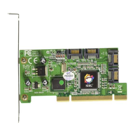
Serial ATA 4-Channel RAID Quick Installation Guide Introducing the Serial ATA 4-Channel RAID The Serial ATA 4-Channel RAID is an ultra high-speed four channel Serial ATA controller for use in Pentium class computers. It achieves burst data transfer rates up to 150MB/s (1.5Gb/s) and supports various brands of... - Page 2 4 Serial ATA data cables (1M) • 2 Dual Connector Serial ATA power cables • 2 "Y" split power cables • Driver CD • Quick Installaton Guide Layout Hard Disk Serial ATA LED Pins Connectors Figure 1. Serial ATA 4-Channel RAID layout...
-
Page 3: Hardware Installation
Hardware Installation General instructions for installing the card are provided below. Since the design of computer cases and motherboards vary, refer to your computer’s reference manual for further information, if needed. Static electricity discharge may permanently damage your system. Discharge any static electricity build up in your body by touching your computer case for a few seconds. - Page 4 Connect the Serial ATA hard disk drive to the system power supply using the included Dual Connector Serial ATA power cable. Connect one end of the Serial ATA data cable to the hard disk drive. Serial ATA cable Power cable adapter Figure 2.
-
Page 5: Raid Arrays
Replace the computer cover and reconnect the power cord. Go to RAID Arrays to configure the RAID BIOS. RAID Arrays RAID Arrays are setup in the Serial ATA 4-Channel RAID BIOS. RAID 0 (Striping) This RAID array to be used on New/Blank hard drives. - Page 6 Select the second drive, press Enter. If applicable select the 3rd and 4th drives pressing enter after each selection. After selecting the last drive, you are asked Are You Sure (Y/N)?, press Y to accept. Press Ctrl+E to exit the BIOS. When asked Are you sure to exit (Y/N)?, press Y to exit.
- Page 7 RAID 1 (Mirror) For New/Blank Hard Drives As the BIOS boots press Ctrl+S or F4 when prompted to enter the RAID BIOS. At the next screen select Create RAID Set, then press Enter. At the next screen select RAID1 then press Enter. Select Auto configuration, then press Enter.
- Page 8 When asked Are You Sure (Y/N)?, press Y. Press Ctrl+E to exit the BIOS. When asked Are you sure to exit (Y/N)?, press Y to exit. Note: If during restart the RAID BIOS reports an incomplete Mirror set, disregard the message, continue booting, and let the Mirror rebuild.
- Page 9 During boot press Ctrl+S or F4 to enter the RAID BIOS. Select Create RAID set then press Enter. Select SPARE DRIVE then press Enter. Select the replacement drive then press Enter. When asked Are You Sure (Y/N)?, press Y to confirm. Press Ctrl+E to exit.
- Page 10 Select the fourth drive, then press Enter. Select Create without data copy then press Enter. When asked Are You Sure (Y/N)?, press Y to accept. Press Ctrl+E to exit the BIOS. When asked Are you sure to exit (Y/N)?, press Y to exit.
- Page 11 During boot press Ctrl+S or F4 to enter the RAID BIOS. Select Create RAID set then press Enter. Select SPARE DRIVE then press Enter. Select the replacement drive then press Enter. When asked Are You Sure (Y/N)?, press Y to confirm. Press Ctrl+E to exit.
- Page 12 When asked Are you sure to exit (Y/N)?, press Y to exit and reboot. Note: The hard disk will show up as Contiguous in the SATARAID5 GUI. JBOD Drive Setup This RAID Array combines the full capacity of two or more hard drives to form one logical drive.
-
Page 13: Deleting Raid Arrays
RAID5 While RAID5 feature is enabled in the SATA Raid 5 BIOS, this RAID Array is not supported by the Serial ATA 4-Channel RAID controller. Please use it at your own risk. Deleting RAID Arrays As the BIOS boots press Ctrl+S or F4 when prompted to enter the RAID BIOS. -
Page 14: Low Level Format
The Low Level Format utility works on single hard drives only, before the RAID set is configured. Software Installation This section provides information on how to install the Serial ATA 4-channel RAID drivers. Windows 2000 For A New Installation Important: During Windows 2000 installation you will be asked to restart several times. - Page 15 When prompted press S to specify the location of the driver. Insert the driver diskette, then press Enter. Select Silicon Image Sil 3114 SoftRaid 5 Controller for Windows 2000, then press Enter. Press Enter to finish driver installation, then follow the on-screen instructions to complete the installation.
- Page 16 Windows XP/Server 2003 (32-bit) For A New Installation A new installation requires a floppy disk for the driver installation. To make this floppy disk, copy the contents of the 32bit folder, found on the driver CD, onto a blank floppy disk then follow the directions below. Setup the RAID array prior to Windows installation.
- Page 17 Remove the driver CD, shutdown Windows, and setup your RAID array. When Windows resumes, go to SATARaid5 GUI on page 19 and install the RAID monitoring utility. Windows XP/Server 2003 (64-bit) For A New Installation A new installation requires a floppy disk for the driver installation.
- Page 18 Insert the driver CD, select Install the software automatically (Recommended), then click Next. Click Finish, remove the driver CD, shutdown Windows, and setup your RAID array. When Windows resumes, go to SATARaid5 GUI on page 19 and install the RAID monitoring utility. To Verify 2000/XP/Server 2003 Installation Right click My Computer, click Manage, click Device Manager.
- Page 19 For An Existing Installation Install the board and boot up Windows. At the Found New Hardware window, click Locate and install the driver automatically (recommended). Insert the driver CD, click Continue. Click Next, then click Close. Remove the driver CD, shutdown Windows, and setup your RAID array.
- Page 20 For Windows XP/Server 2003 For 32-bit: Click Run, type D:\32bitgui.msi, then click OK. (Change D: to match your CD-ROM drive letter) For 64-bit: Click Run, type D:\64bitgui.msi, then click OK. (Change D: to match your CD-ROM drive letter) For Windows Vista For 32-bit: In Start Search box, type D:\32bitgui.msi, then press Enter.
- Page 21 Device Configuration RAID Groups window window RAID Groups window This window identifies SATA host adapters and configured RAID groups. Selecting each RAID group in the RAID Groups window, members consisting of the RAID group will be highlighted in the Device Configuration window.
- Page 22 SATARAID 5 Configuration Menu SATARAID5 configuration menu includes customization of the settings for Log File, Popup and Advanced Options. By clicking on File, then Configuration, the user may customize the settings for Log File, Popup and Advanced Options tabs. Log File The log file is used to store event information received from all the RAID drivers.
- Page 23 Popup The popup window is a visual notification that an event has occurred. The popup window can be disabled or set to popup for only certain event levels. The different levels are: Informational - The popup window will be displayed for the following events: - Informational - Warnings...
- Page 24 Advanced RAID Features: When this feature is selected and the user selects to create RAID group, if the RAID group to be created is fault tolerant group (RAID1), the user will be able to select Improper Shutdown Policy in the Create RAID Group dialog box. The Advanced RAID Features are not supported for Legacy RAID groups.
- Page 25 Device Summary This command displays the Segment Summary window to show all physical devices' segments. RAID Group Menu Command Create RAID Group This command displays a dialog box to let user create a RAID group, the user needs to specify the following parameters: RAID Group Label: Provides a name for the RAID group.
- Page 26 RAID Group Summary This command displays a dialog box to show all RAID groups' group ID, configuration and status. The RAID Group Summary window has it's own menu bar. All options available via the menu bar are shown below. Sorting: This command displays a dialog box to let the user choose up to 3 items to sort RAID group items in the RAID Group Summary window.
- Page 27 Resume: This command allows the user to resume the suspended task items. Cancel: This command allows the user to cancel the selected task items. Delete: This command displays a dialog box to let the user delete the selected task items. Event Log This command displays the Event Log window.
- Page 28 Capacity: Select from a list of RAID group sizes. Chunk Size: Select one value from the available list. Rebuild Priority: Select from the available list. RAID 0 and virtual disk do not require this. 10 is the highest level of rebuild priority which means that rebuild times will be faster but will take more CPU resources to rebuild.
- Page 29 Blank Page...
- Page 30 Blank Page...
-
Page 31: Technical Support And Warranty
Step 1: Submit your RMA request. Go to www.siig.com, click Support, then RMA to submit a request to SIIG RMA. If the product is determined to be defective, an RMA number will be issued. Step 2: After obtaining an RMA number, ship the product. - Page 32 Fremont, CA 94538-3152, USA Ph: 510-657-8688 Serial ATA 4-Channel RAID is a trademark of SIIG, Inc. SIIG and the SIIG logo are registered trademarks of SIIG, Inc. Microsoft, Windows and Windows Vista are either registered trademarks or trademarks of Microsoft Corporation in the United States and/or other countries. Pentium is a registered trademark of Intel Corporation.
Need help?
Do you have a question about the Serial ATA 4-Channel RAID and is the answer not in the manual?
Questions and answers