Sign In
Upload
Manuals
Brands
Allied Telesis Manuals
Switch
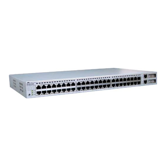
AT-8350GB
Allied Telesis AT-8350GB Manuals
Manuals and User Guides for Allied Telesis AT-8350GB. We have
1
Allied Telesis AT-8350GB manual available for free PDF download: Installation Manual
Allied Telesis AT-8350GB Installation Manual (104 pages)
Fast Ethernet Switch
Brand:
Allied Telesis
| Category:
Switch
| Size: 1 MB
Table of Contents
Table of Contents
5
How this Guide Is Organized
9
Preface
9
Document Conventions
10
Where to Find Web-Based Guides
11
Contacting Allied Telesyn Technical Support
12
Online Support
12
Telephone Support
12
Management Software Updates
13
For Sales or Corporate Information
14
Chapter 1 Product Description
15
Summary of Features
15
Location of Components
16
Figure 1 AT-8350GB Front Panel
16
Figure 2 AT-8350GB Back Panel
16
Hardware Features
17
Twisted Pair Ports
17
Figure 3 Twisted Pair Ports
17
Figure 4 RJ-45 Connector and Port Pin Layout
19
Gigabit Interface Converter Slots
21
Figure 5 GBIC Slots
21
Figure 6 Example of a GBIC Module
21
Stacking Ports
22
Figure 7 Stacking Ports
22
Expansion Slot
23
Figure 8 Expansion Slot
23
System Leds
24
Figure 9 System Leds
24
10/100 Mbps Port Leds
25
Figure 10 Port Leds
25
Figure 11 Port Mode Leds and Button
25
Gigabit Connector Leds
27
Figure 12 Gigabit Connector Leds
27
Expansion Module Leds
28
Figure 13 Expansion Module Port Leds
28
Terminal Port
29
Figure 14 RS-232 Terminal Port
29
AC Power Connector
30
Figure 15 AC Power Connector
30
Redundant Power Supply Units
31
Figure 16 Redundant Power Supply Connector
31
Figure 17 AT-RPS2001 Redundant Power Supply Unit
31
Figure 18 AT-RPS2004 Front & Back Panels
32
Figure 19 AT-RPS2004 Power Supply Leds
32
Figure 20 14-Pin Molex Connector Port Pin Layout
34
Software Features
35
AT-S41 Management Software
35
Figure 21 Local Management
36
Figure 22 AT-S41 Main Menu - Local Management Session
36
Figure 23 URL Field of a Web Browser
37
Figure 24 Web Browser Management Home Page
37
Spanning Tree Protocol (STP)
38
Port-Based and Tagged Vlans
39
Quality of Service (Qos)
39
IGMP Snooping
40
Dynamic Host Configuration Protocol (DHCP)
41
Port Monitoring
41
Port Trunking
41
Figure 25 Port Trunk Example
43
Port Security
44
A few Basics to Ethernet Switching
45
MAC Address Table
45
Duplex Mode
46
Store and Forward
46
Backpressure and Flow Control
46
Network Topologies
48
Power Workgroup Topology
48
Figure 26 Power Workgroup Topology
48
Collapsed Backbone - Hub Topology
49
Figure 27 Collapsed Backbone - Hub Topology
49
Switch Stacking Topology
50
Figure 28 Switch Stacking Topology
50
Chapter 2 Installation
51
Installation Safety Precautions
52
Selecting a Site for the Switch
54
Required Cables
55
Unpacking the Switch
56
Installing the Switch on a Desktop
57
Figure 29 Attaching Rubber Feet to Switch
57
Installing the Switch in a Rack
58
Figure 30 Attaching a Rack-Mounting Bracket
58
Figure 31 Installing the Switch in a Rack
58
Installing an Optional GBIC Module
59
Figure 32 GBIC Module
59
Figure 33 Optical Bore & Ferrule of GBIC Module
60
Figure 34 Installing a GBIC Module
61
Installing an Expansion Module
62
Figure 35 Removing the Expansion Slot Faceplate
63
Figure 36 Installing a Module
63
Creating a Switch Stack
65
Figure 37 Stack of Three Switches
66
Figure 38 a Stack of Four Switches
66
Cabling the Switch
67
Figure 39 Connecting the Twisted Pair Data Cables
67
Figure 40 Removing the Dust Cover from a GBIC Module
68
Figure 41 Attaching a Fiber Optic Cable to a GBIC Module
69
Powering the Switch
70
Figure 42 FAULT LED
70
Figure 43 AT-RPS2001 Redundant Power Supply
71
Installing the AT-RPS2001 Unit
71
Figure 44 Connecting the AT-RPS2001 Unit to the Switch
72
Figure 45 Installing the AT-RPS2001 Unit Onto the Switch
72
Figure 46 Connecting the AT-RPS2001 Unit
73
Installing the AT-RPS2004 Unit
74
Figure 47 Attaching a Rack-Mounting Bracket
75
Figure 48 Installing the Power Supply Unit in a Rack
75
Figure 49 Connecting the AC-Power to the AT-RPS2004 Unit
76
Figure 50 Connecting the RPS Connector
76
Figure 51 Connecting to the AT-RPS2004 Unit
77
Starting a Local Management Session
78
Figure 52: Connecting the Null Modem Management Cable to the RS-232 Terminal Port
78
Figure 53 AT-S41 Login Prompt - Local Management Session
79
Figure 54 AT-S41 Main Menu - Local Management Session
80
Warranty Registration
81
Chapter 3 Troubleshooting
83
Appendix A Technical Specifications
89
Physical Specifications
89
Environmental Specifications
89
Power Specifications
89
Safety and Electromagnetic Emissions Certifications
90
Standards
90
SNMP Support
90
Appendix B
91
Default Switch Settings
91
Appendix C
93
Translated Electrical Safety and Emission Information
93
Advertisement
Advertisement
Related Products
Allied Telesis AT-8326GB
Allied Telesis AT-8324
Allied Telesis AT-8316F/VF
Allied Telesis AT-8316F/SC
Allied Telesis AT-8316F/MT
Allied Telesis AT-8324SX
Allied Telesis AT-8516F/SC Series
Allied Telesis AT-8948
Allied Telesis AT-8100S/24POE
Allied Telesis AT-8100S/48POE
Allied Telesis Categories
Switch
Network Router
Media Converter
Network Hardware
Wireless Access Point
More Allied Telesis Manuals
Login
Sign In
OR
Sign in with Facebook
Sign in with Google
Upload manual
Upload from disk
Upload from URL