Table of Contents
Troubleshooting

Related Manuals for Marco marco EcoSmart


Summary of Contents for Marco marco EcoSmart
- Page 1 EcoSmart boiler SERVICE MANUAL Marco Beverage Systems Ltd. Ireland Tel: (01) 295 2674 63d Heather Road, Ireland Fax: (01) 295 3715 Sandyford Industrial Estate, UK Tel: (0207) 274 4577 Dublin 18, UK Fax: (0207) 978 8141 Republic of Ireland...
-
Page 2: Table Of Contents
CONTENTS: INTRODUCTION SAFETY INSTRUCTIONS BASIC INSTRUCTIONS 3.1. Installation Details 3.2. Troubleshooting 3.3. Maintenance 3.4. Cleaning 3.5. Limescale 3.6. Cautions and Safety Tips TECHNICAL DATA 4.1. General Description 4.2. External Arrangement 4.3. Access to internal components 4.4. Internal Arrangement 4.5. PCBs 4.5.1. -
Page 3: Introduction
1. INTRODUCTION: The information provided in this manual is intended to assist in the installation and maintenance of the Marco EcoSmart Boiler. Please read the instructions carefully to prevent accidents and ensure an efficient installation. This manual is not a substitute for any safety instructions or technical data affixed to the machine or its packaging. -
Page 4: Basic Instructions
3. BASIC INSTRUCTIONS : 3.1. INSTALLATION DETAILS: Electrical installation: Electrical specification: 2.8kW-230V-50Hz A moulded 13A plug is factory fitted. A suitable 13A outlet is all that is required. Plumbing installation procedure: Mains water pressure required (limits): 5-50psi (35-345kPa) Fit a stop Valve on a cold water line and attach a 3/4" BSP male fitting, (e.g. -
Page 5: Troubleshooting
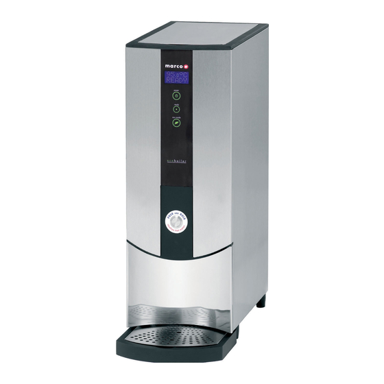
Power Button EcoMode Button Figure 1: Machine User Interface NOTE: Because the boiler is electronically controlled no priming is necessary. The element cannot switch on until a safe level of water is reached. PLEASE REFER TO INSTRUCTION BOOKLET FOR TEMPERATURE CALIBRATION. 3.2. -
Page 6: Maintenance
3.3. MAINTENANCE: Marco machines have been designed to give many years of trouble free service. Marco Beverage Systems manufacture and test to ISO9002:2000 standard. The only regular maintenance required is occasional de-scaling. Descaling Procedure: Isolate machine from power supply. Isolate machine from water supply. ALLOW TO COOL COMPLETELY! Drain water from machine. -
Page 7: Technical Data
4. Technical Data: 4.1. GENERAL DESCRIPTION: EcoSmart PB10 1000677 and 1000678. 1000677 1000678 Dimensions Height (mm) Width (mm) Depth – counter footprint (mm) Depth incl. Drip Tray (mm) Height Dispense to Drip tray (mm) Performance Immediate Draw-Off (litres) Max. Hourly Output (litres/hour) Electrical Connection 2.8kW,230V, c/w 1.5m... -
Page 8: Access To Internal Components
4.3. ACCESS TO INTERNAL COMPONENTS: To access the tank: Allow to cool. Remove the Ensure that the tank is cool, The tank is now accessible outer lid. before removing inner lid. To for cleaning. remove inner lid, undo 4 butterfly nuts To access the internal components: Ball Stud Spring... - Page 9 Disconnect the machine from the electrical supply. Allow to cool sufficiently. The metal Front Fascia Top and Bottom panels are fixed to the surround with ball studs that lock into spring clips mounted in the surround panel – refer to picture above. To separate the ball studs from the spring clips insert a flat headed screwdriver at the locations indicated on the picture and lever apart the front panels from the surround.
-
Page 10: Internal Arrangement
4.4. INTERNAL ARR ANGEMENT: High Level Probe Assembly (2300463) Mid Level Probe Assembly (2300463) Dispense Solenoid (1502156) Low Level Probe Assembly (2300463) Boil Dry Thermal Cutout Switch Element 2.8kW 230V (1500985) P.C.B Eco Slave (1600354) Valve Inlet Solenoid 240V - 2L/min (1502191) Service Manual 1000677 EcoSmart PB10 1000678 EcoSmart hiDeck 221110.doc Page 10 of 19... -
Page 11: Pcbs
4.5. PCBs: .1. PCB Eco Slave 1600354: COMPONENTS OF PCB ECO SLAVE: Dispense Solenoid Tab Inlet Solenoid Tab Neutral Tabs Transformer Mains Live In Tab Relays - Heater Switch the element Heater Tab On/Off 2-way Connector Short circuited on this EcoSmart machines – power switch controlled through the display LED 5-way Connector 10. -
Page 12: Pcb Ecosmart Display - 1600357
4.5.2 P.C.B Ecosmart Display 1600357 1. Power On/Off LED‟s and Button shows that machine is switched on 2. Status LED‟s displays Error signals via a flashing RED LED 3. Eco Mode On/Off LED‟s and Button 4.5.5 PCB Displa y Label Requirements 1000677 1000678 Replacing THE EcoSmart DISPLAY AND APPLYING LABELS. -
Page 13: Troubleshooting - Diagnostic Guide
4.6. TROUBLESHOOTING – DI AGNOSTIC GUIDE: NOTE FOR THE ECOSMART RANGE IN ADDITION TO THE STATUS LED FLASHING TO INDICATE AN ERROR – THE DISPLAY WILL ALSO PROVIDE INFORMATION 1 FLASH CYCLE – LOW LEVEL PROBE DISCONNECTED Display pattern: 1 flash then a short pause - repeated. Check and Action Check the wiring to the Low Level probe and the Probe inside the tank. - Page 14 This is a non recoverable error. The machine needs to be reset when this problem is solved. Probable causes: 1. The elements have failed 2. Wiring fault Action required: 1. Check that the resistance on the elements. If there is a reasonable resistance (15-25Ω)on the element it probably has not failed, so the wiring might be at fault.
-
Page 15: Tank Components
4.7. Tank Components The tank internals are detailed below. Care should be taken when cleaning inside the tank. The level probes provide much of the control inputs into the PCB and are critical to the operation of the machine. The wiring to these should be checked regularly and the probes themselves should be cleaned whenever the machine is serviced. -
Page 16: Descaling Procedure
4.8. Descaling Procedure To descale the machine thouroughly: Unplug the machine. Disconnect from the water supply. Drain as much water from the tank as possible. Remove the lids and allow the machine to cool completely. Drain all the water from the machine. Attempt to remove as much scale as possible by hand. - Page 17 4.9. Wiring Diagram 10006 77 and 10000678 EcoSmart PB10 Service Manual 1000677 EcoSmart PB10 1000678 EcoSmart hiDeck 221110.doc Page 17 of 19...
-
Page 18: Wiring Diagram 1000678 Ecosmart Hideck
Service Manual 1000677 EcoSmart PB10 1000678 EcoSmart hiDeck 221110.doc Page 18 of 19... -
Page 19: Spare Parts List
4.13. Spare Parts List Part Description Model Variant Number 1000677 1000678 1600354 P.C.B Eco Slave 16 0 03 5 7 P. C. B Ec os m art D is p l a y 1600357K PCB 357 Spares Kit 1401874 Spacer Nylon 3.1x8x5mm ( qty of 4 req.per machine) 1502191 Valve Inlet Solenoid 240V - 2L/min...
Need help?
Do you have a question about the marco EcoSmart and is the answer not in the manual?
Questions and answers