Table of Contents
Advertisement
Advertisement
Table of Contents
Troubleshooting

Related Manuals for Marco Ecoboiler WMT5


Summary of Contents for Marco Ecoboiler WMT5
- Page 1 Ecoboiler WMT5 Ecoboiler WMPB5 Ecoboiler WMT3 Ecoboiler WMPB3 SERVICE MANUAL Ireland Tel: (01) 295 2674 Marco Beverage Systems Ltd. Ireland Fax: (01) 295 3715 63d Heather Road, Sandyford Industrial Estate, Dublin 18, UK Tel: (0207) 274 4577 Republic of Ireland...
-
Page 2: Table Of Contents
CONTENTS: PAGE INTRODUCTION SAFETY INSTRUCTIONS BASIC INSTRUCTIONS 3.1. Installation Details 3.2. Operation 3.3. Calibration 3.4. Troubleshooting 3.5. Maintenance 3.6. Cleaning 3.7. Limescale 3.8. Cautions and Safety Tips TECHNICAL DATA 4.1. General Description 4.2. External Arrangement 4.3. Internal Arrangement 4.4. Access to internal components 4.5. -
Page 3: Introduction
Only technicians or service providers authorised by Marco should carry out installation and maintenance of these machines. Marco accepts no responsibility for any damage or injury caused by incorrect or unreasonable installation and operation. 2. SAFETY INSTRUCTIONS: ... -
Page 4: Basic Instructions
Suitable cabling and fusing for a 2.4-3 kW circuit. o Ensure the machine is fully earthed. Plumbing installation procedure: Note: Marco recommend that this machine be positioned over a counter with a drainage facility. Marco cannot be held responsible for any flood damages. ... -
Page 5: Calibration
3.5. MAINTENANCE: Marco machines have been designed to give many years of trouble free service. Marco Beverage Systems manufacture and test to ISO9002:2000 standard. The only regular maintenance required is occasional de-scaling. -
Page 6: Cleaning
3.6. CLEANING: The exterior of these machines may be cleaned with a damp cloth and a light detergent. Do not use abrasive cloths or creams, as this will spoil the finish of the machine. Do not use a water jet or spray. -
Page 7: External Arrangement
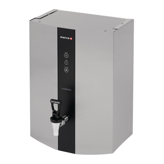
4.2. EXTERNAL ARRANGEMENT: Top tank access Lid Side Panel Fixed centre panel Tap/ Push Button 4.3. INTERNAL ARRANGEMENT: PCB Ecoboiler Control (1600345) High Level Probe Assembly (2300463) PCB Bracket Mid Level Probe Assembly (2300463) Terminal Mains Connector 1502011 Thermal Switch 130Deg (1502087) Valve inlet Solenoid (1502190) -
Page 8: Access To Internal Components
4.4. ACCESS TO INTERNAL COMPONENTS: ANY MAINTENANCE WORK ON ANY ECOBOILER PRODUCT SHOULD ONLY BE CONDUCTED BY A TRAINED SERVICE ENGINEER. Removal Disconnect the machine from the electrical supply. Allow to cool sufficiently. The removable Side Panels are fixed at the top of the machine. -
Page 9: Pcbs
Inlet Solenoid Access: To access the inlet solenoid, Unscrew the two cross- recessed pan headed screws holding the bracket in place. 4.5. PCBs: 4.5.1. PCB Layout: Internal PCB Layout: PCB Ecoboiler Control (1600345): Controls the heater switching Controls the water inlet switching ... -
Page 10: Pcb Ecoboiler Control - 1600345
4.5.2. PCB Ecoboiler Control: COMPONENTS OF PCB ECOBOILER CONTROLLER 2008: 1. Dispense Solenoid Tab 2. Inlet Solenoid Tab 3. Neutral Tabs 4. Transformer 5. Mains Live In Tab 6. Relays - Heater Switch the element 7. Heater Tab 8. On/Off 2-way Connector Short circuited on this Ecoboiler machines –... -
Page 11: Pcb Ecoboiler Display 10L - 1600349
Connects to Daughter PCBs – allows switching of more than one element 12. External Connector 13. Thermistor Connector 14. Dip Switch – 3 way Allows selection of software for specific machine 15. Tactile Switch For use during calibration procedure (refer to Calibration in Sec 3.3) ... - Page 12 Probable causes: 1. The water level is below the low level probe, which is normal when the machine fills for the first time. (Can be flashing for up to 2 min at start up) 2. The low level probe wire is disconnected, or there is another wiring fault (e.g.
- Page 13 5 FLASH CYCLE – THERMISTOR SHORT CIRCUIT Display pattern: 5 flashes then a short pause - repeated. Electronic check: This indicates that the Thermistor is measuring zero resistance. It assumes the thermistor has failed sort circuit. The element and inlet valve are turned OFF when this error is detected ...
-
Page 14: Tank Components
4.7. Tank Components The tank internals are detailed below. Care should be taken when cleaning inside the tank. The level probes provide much of the control inputs into the PCB and are critical to the operation of the machine. The wiring to these should be checked regularly and the probes themselves should be cleaned whenever the machine is serviced. -
Page 15: Descaling Procedure
Drain water from machine, drain hose is located at the base of the machine, which is accessible by removing right side panel. Use ScaleKleen, Marco part No. 8000270 or similar. Follow instructions carefully. Remove lid located on the top of machine. - Page 16 4.9. W iring Diagrams Service Manual Ecoboiler wallmount 1000671 100676 061010 Page 16 of 18...
- Page 17 Service Manual Ecoboiler wallmount 1000671 100676 061010 Page 17 of 18...
-
Page 18: Spare Parts List
Exterior Lid ECOW-015F Base cover plate ECOW-006F WM Clean out door ECOW-020F Left Wing ECOW-021F Right Wing ECOW-012F Center Panel ECOW-019F THERMAL SWITCH BRACKET MARCO is an ISO9001:2000 Registered Company. Service Manual Ecoboiler wallmount 1000671 100676 061010 Page 18 of 18...
Need help?
Do you have a question about the Ecoboiler WMT5 and is the answer not in the manual?
Questions and answers