Table of Contents
Troubleshooting

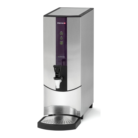
Related Manuals for Marco Ecoboiler T20


Summary of Contents for Marco Ecoboiler T20
- Page 1 Ecoboiler T20 & T30 SERVICE MANUAL Marco Beverage Systems Ltd. Ireland Tel: (01) 295 2674 63d Heather Road, Ireland Fax: (01) 295 3715 Sandyford Industrial Estate, Dublin 18, UK Tel: (0207) 274 4577 UK Fax: (0207) 978 8141 Republic of Ireland...
-
Page 2: Table Of Contents
PCB Display 20/T30 Ecoboiler (1600349) Troubleshooting – Diagnostic guide 4.6. 4.7. Tank Components 4.8. Descaling procedure 4.9. Wiring Diagram 1000660 Ecoboiler T20-3 4.10. Wiring Diagram 1000661 Ecoboiler T20-6 and T30 4.11. Spare Parts List T20-T30 Servuce Manual 11/07/2014 Page 2 of 18... -
Page 3: Introduction
1. INTRODUCTION: The information provided in this manual is intended to assist in the installation and maintenance of the Marco Ecoboiler Water boiler. Please read the instructions carefully to prevent accidents and ensure an efficient installation. This manual is not a substitute for any safety instructions or technical data affixed to the machine or its packaging. -
Page 4: Basic Instructions
3.1. INSTALLATION DETAILS: Electrical installation: EcoBoiler T20-3 (2.8kW) - A moulded 13A plug is factory fitted. A suitable 13A outlet is all that is required. EcoBoiler T20-6/T30 (5.6kW) – Needs to be hard-wired to a dedicated 30amp spur. -
Page 5: Troubleshooting
Power Button Ready/Status Indicator Ecomode Button Figure 1: Machine User Interface NOTE: Because the boiler is electronically controlled no priming is necessary. The element cannot switch on until a safe level of water is reached. 3.3. TROUBLESHOOTING The Ready/Status light signals various errors or problems. A cycle of red flashes indicates an error. -
Page 6: Maintenance
3.4. MAINTENANCE: Marco machines have been designed to give many years of trouble free service. Marco Beverage Systems manufacture and test to ISO9002:2000 standard. The only regular maintenance required is occasional de-scaling. Descaling Procedure: Isolate machine from power supply. -
Page 7: Technical Data
4. Technical Data: 4.1. GENERAL DESCRIPTION: ECO Boiler T20-3, T20-6, T30. T20-3 T20-6 Dimensions Height (mm) Width (mm) Depth – counter footprint (mm) Depth – to front of Tap (mm) Depth incl. Drip Tray (mm) Performance Immediate Draw-Off (litres) Max. Hourly Output (litres/hour) Electrical Connection 2.8kW, 230V, c/w 1.5m flex and moulded plug... -
Page 8: Access To Internal Components
4.3. ACCESS TO INTERNAL COMPONENTS: To access the tank: Allow to cool. Remove the Ensure that the tank is cool, The tank is now accessible outer lid. before removing inner lid. To for cleaning. remove inner lid, undo 4 butterfly nuts To access the internal components: Ball Stud Spring... - Page 9 This allows access to most of the internal components and the machine does not need to be drained for most maintenance or service operations. If further access is required, the plastic Front Fascia Middle panel should be removed by unscrewing the four cross recessed pan headed screws.
-
Page 10: Internal Arrangement
4.4. INTERNAL ARR ANGEMENT: 4.5. PCBs: 4.5.1. PCB La yout: Internal PCB Layout: PCB Ecoboiler Control (1600345): Controls the heater switching Controls the water inlet switching Controls tank temperature/temperature adjustment PCB Ecoboiler Display 10L (1600349) consists of: ... - Page 11 4.5.2. PCB Ecoboiler Control (1600345): COMPONENTS OF PCB ECOBOILER CONTROLLER 2008: Dispense Solenoid Tab Inlet Solenoid Tab Neutral Tabs Transformer Mains Live In Tab Relays - Heater Heater Tab On/Off 2-way Connector Shorted with Jumper on Ecoboiler machines – power switch controlled through the display PCB LED 5-way Connector Earth Tab...
-
Page 12: Pcb Ecoboiler Control (1600345)
4.5.3. PCB Displa y T20/T30Ecoboiler (1600349) 1. Power On LED’s shows that machine is switched on 2. Power On/Off switch 3. Status LED’s displays error signals via a flashing Red LED 4. Eco Mode On LED’s 5. Eco Mode On/Of Switch 6. -
Page 13: Troubleshooting - Diagnostic Guide
4.6. TROUBLESHOOTING – DI AGNOSTIC GUIDE: 2 FLASH CYCLE – BELOW LOW LEVEL Display pattern: 2 flashes then a short pause - repeated. Electronic check and action: This indicates that the low level circuit is open i.e. the probe is not in contact with the ... - Page 14 4.6. TROUBLESHOOTING – DI AGNOSTIC GUIDE cont: Action required: 1. Check that the resistance on the elements. If there is a reasonable resistance (15-25Ω) on the element it probably has not failed, so the wiring might be at fault. 5 FLASH CYCLE – THERMISTOR SHORT CIRCUIT Display pattern: 5 flashes then a short pause - repeated.
-
Page 15: Tank Components
There are 3 level probes on the T20 and T30 Ecoboiler versions. The Ecoboiler T20/T30 tank is shown below – only the low level probe is visible in the picture. 4.8. Descaling Procedure To descale the machine thoroughly: Unplug the machine. -
Page 16: Wiring Diagram 1000660 Ecoboiler T20-3
4.9. Wiring Diagram 1000662 Ecoboiler T20 -3 T20-T30 Servuce Manual 11/07/2014 Page 16 of 18... -
Page 17: Wiring Diagram 1000661 Ecoboiler T20-6 And T30
4.10. Wiring Diagrams 1000663 Ecoboiler T20-6 and T30 T20-T30 Servuce Manual 11/07/2014 Page 17 of 18... -
Page 18: Spare Parts List
1502190 Valve Inlet Solenoid 1500985 Element 2.8kW 230V 1600691 Thermistor Assembly 2300463 Level Probe Assembly Drip Tray Complete – Ecoboiler T20 2300192 Drip Tray Complete – Ecoboiler T30 2300274 2300384 Lid Inner Ecoboiler Complete 2300391 Lid Outer Ecoboiler T20 2300392 Lid Outer Ecoboiler T30 Label Facia –...
Need help?
Do you have a question about the Ecoboiler T20 and is the answer not in the manual?
Questions and answers