Table of Contents
Advertisement
This appliance may be constructed with a vertical or horizontal direct vent termination system.
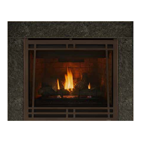
GC150 HEAT CIRCULATING SERIES GAS APPLIANCE
AND INSTALLATION INSTRUCTIONS
MODELS: GC150, GC150L, GC150E, GC150LE
WARNING: If the information in
these instructions is not followed
exactly, a fire or explosion may result
causing property damage, personal
injury or death.
-Do not store or use gasoline or other flam-
mable vapors and liquids in the vicinity of
this or any other appliance.
-WHAT TO DO IF YOU SMELL GAS
Do not try to light any appliance.
l
Do not touch any electrical switch.
l
Do not use any phone in your
l
building.
Immediately call your gas supplier
l
from a neighbor's phone. Follow
the gas supplier's instructions.
If you cannot reach your gas sup-
l
plier, call the fire department.
-Installation and service must be performed
by a qualified installer, service agency or
the gas supplier.
Electrician: Please refer to page 14 for wiring instructions.
Plumber:
Framer:
Heatilator
1915 W. Saunders Street
Mt. Pleasant, IA 52641
A Division of Hearth Technologies Inc.
OWNER'S MANUAL
Please refer to page 6 and 13 for gas connection information.
Please refer to page 7 for framing specifications.
This manual must be used for installation of the
GC150 Series Gas Appliance and retained by the
homeowner for operating and maintenance
instructions.
Advertisement
Table of Contents

Related Manuals for Heatiator GC150


Summary of Contents for Heatiator GC150
- Page 1 MODELS: GC150, GC150L, GC150E, GC150LE This manual must be used for installation of the WARNING: If the information in GC150 Series Gas Appliance and retained by the these instructions is not followed homeowner for operating and maintenance exactly, a fire or explosion may result instructions.
-
Page 2: Table Of Contents
11. Be sure to provide adequate clearances around the 4. The GC150 fireplace is a vented gas fireplace. Do air openings into the combustion chamber and ade- not burn wood or other material in this appliance. -
Page 3: Listings And Code Approvals
The GC150 is a vented gas fireplace. Combustion air is supplied from outside, not from inside the house as with other types of fireplaces. While a significant amount of heat is created by the GC150, it is not intended to be and, therefore, should not be used as a heater. -
Page 4: Fireplaces System Components And Dimensions
GC150 SERIES DIRECT VENT GAS APPLIANCE III. FIREPLACE SYSTEM COMPONENTS The table below is a list of only those components illustration of each component can be found on which may be safely used with this fireplace. An page 5. Catalog Number... - Page 5 GC150 SERIES DIRECT VENT GAS APPLIANCE Wall Shield Firestop Spacer Vertical Termination Cap Roof Flashing EL45 Actual Useable Vent Section length length VK12 12" ⁄ " VK24 24" ⁄ " VK36 36" ⁄ " VK48 48" ⁄ " Vent Sections...
-
Page 6: Pre-Installation Preparation
This appliance may be installed along a wall, across a adjustment. Input rate is 22,500 Btu/hr. For propane gas, corner or use an exterior chase. The GC150 Series the inlet gas supply pressure must be at least 11.0 inches may be installed at a height level with the floor, or it water column and a maximum 14.0 inches water column. -
Page 7: Framing The Fireplace
Note: The remote wall switch must be wired prior to applying the finishing material in order to avoid reconstruction. Figure 2a Framing the Fireplace The GC150 Series Gas Appliance will fit a framed opening of 40" w ⁄ " d ⁄... -
Page 8: Step-By-Step Installation Of The Fireplace System
GC150 SERIES DIRECT VENT GAS APPLIANCE V. STEP-BY-STEP INSTALLATION OF THE FIREPLACE SYSTEM WARNING! BEFORE STARTING, DO THE FOLLOWING: WEAR GLOVES AND SAFETY GLASSES FOR PROTECTION. KEEP HAND TOOLS IN GOOD CONDITION. SHARPEN CUTTING EDGES AND MAKE SURE TOOL HANDLES ARE SECURE. - Page 9 GC150 SERIES DIRECT VENT GAS APPLIANCE b. Amount of venting required. Due to the many different combinations that can be used when con- structing venting, the number of vent sections required can only be determined by the installer. Note: Horizontal runs will require the use of one Vent Support (VS4) for every 3' of vent.
- Page 10 GC150 SERIES DIRECT VENT GAS APPLIANCE 5. Termination Cap. Vent termination must not minimum dimensions for each termination applica- be recessed into the wall or exterior sheeting. tion. Or, follow ANSI Z223.1, latest edition. Figure 9 illustrates termination cap locations and...
-
Page 11: Vertical Termination
GC150 SERIES DIRECT VENT GAS APPLIANCE To install the termination cap, slide the cap vent sections into the vent sections as shown in Figures 10A and 10B. Secure the cap flush to the wall using the eight 1" fasteners provided. Seal the cap to the wall with a mastic such as silicone caulking. - Page 12 GC150 SERIES DIRECT VENT GAS APPLIANCE 2. Preparing the ceiling for firestop spacers. Mark and cut out an opening in the ceiling for the firestop spacer. Frame the opening with the same size lumber used in the ceiling joists. Unless the flue if offset, frame the 10"...
- Page 13 GC150 SERIES DIRECT VENT GAS APPLIANCE 10. Termination cap. Major building codes spec- STEP 3 - Double Checking ify a minimum venting system height above the When construction of the entire vent system has roof top depending on roof pitch. See Figures 15 been completed, double check to make sure all and 16.
- Page 14 GC150 SERIES DIRECT VENT GAS APPLIANCE STEP 6 - Lower Panel Removal To remove the lower panel, gently lift and pull on the out- side edges of the panel as shown in Figure 18. To replace the panel, reverse this action.
- Page 15 GC150 SERIES DIRECT VENT GAS APPLIANCE B. STANDING PILOT IGNITION 1. Appliance requirements. A wiring diagram is shown in Figure 20. 2. Optional Accessories Requirements. Wiring for optional accessories should be done now to avoid reconstruction. WA R N I N G ! This appliance DOES NOT require a 110VAC supply for operation.
- Page 16 GC150 SERIES DIRECT VENT GAS APPLIANCE STEP 10 - Screen Removal STEP 8 - Attaching Hood After removing the hood and lower panel, you are The hood is to be located just above the glass panel. Four screws are visible just inside the upper section able to remove the protective fire screen.
- Page 17 GC150 SERIES DIRECT VENT GAS APPLIANCE The left Side Log is placed with the short portion of the “Y” into the indent on the Front Log. The long portion of the “Y” leans against the Rear Log and the leg portion of the Side Log is placed on the side log support (located on the left hand side of the firebox).
- Page 18 GC150 SERIES DIRECT VENT GAS APPLIANCE Figure 29 - Placing the Lava Rock and Vermiculite STEP 13 - Placing the Lava Rock, Vermiculite and Figure 30 Rock Wool Placing the Rock Wool Spread the lava rock over the area in front of the burner and the two side pans.
-
Page 19: Operating Instructions
GC150 SERIES DIRECT VENT GAS APPLIANCE VI. OPERATING INSTRUCTIONS STANDING PILOT FOR YOUR SAFETY READ BEFORE LIGHTING WARNING! If you do not follow these instructions exactly, a fire or explosion may result causing property damage, personal injury or loss of life. -
Page 20: For Your Safety
GC150 SERIES DIRECT VENT GAS APPLIANCE Determining the Ignition Type To determine whether your appliance is an electronic ignition or a standing pilot ignition, remove the lower panel to examine the wiring system. If your system has a red ignitor button (as shown in Figure 1), you own a standing pilot ignition fireplace. - Page 21 GC150 SERIES DIRECT VENT GAS APPLIANCE WARNING! CHILDREN AND ADULTS SHOULD BE ALERTED TO THE HAZARDS OF HIGH SURFACE TEM- PERATURES AND SHOULD STAY AWAY TO AVOID BURNS OR CLOTHING IGNITION. YOUNG CHILDREN SHOULD BE CAREFULLY SUPERVISED WHEN THEY ARE IN THE SAME ROOM AS THE APPLIANCE.
-
Page 22: Standing Pilot Operation
GC150 SERIES DIRECT VENT GAS APPLIANCE A. STANDING PILOT OPERATION Note: Keep the area near the appliance 1. Initial and Seasonal Lighting Procedure. Initial clear and free from combustible materials, lighting constitutes the first time the appliance has gasoline and other flammable vapors and been lit after installation. -
Page 23: Electronic Ignition Operation
GC150 SERIES DIRECT VENT GAS APPLIANCE If you own a standing pilot ignition, skip section B and 2. Seasonal Shutdown. When the burning sea- continue with Step 2. son comes to an end, the entire system should be shut down. Note: There may be a rocker switch on a column in the control area, as well as a wall switch. -
Page 24: Maintenance Instructions
GC150 SERIES DIRECT VENT GAS APPLIANCE VII. MAINTENANCE INSTRUCTIONS Cleaning the burner and control compartment Keep the burner and control compartment clean by brushing and vacuuming at least once a year. Always turn off the gas valve and the ON/OFF switch before cleaning. -
Page 25: Trouble Shooting
GC150 SERIES DIRECT VENT GAS APPLIANCE VIII. TROUBLE SHOOTING ELECTRONIC IGNITION (GC150E) Problem Cause Corrective Action A. Defective ignitor; loose 1. Spark ignitor will Check for loose connections on electrode and ignitor. Refer not light burner wire. to the wiring diagram on page 13 for assistance. -
Page 26: Standing Pilot
GC150 SERIES DIRECT VENT GAS APPLIANCE STANDING PILOT Problem Cause Corrective Action 1. Spark ignitor will not A. Defective ignitor. Replace ignitor. light pilot after B. Misaligned electrode. Spark should be approximately 1/8” to bottom of pilot hood. Adjust gap to give repeated pressing of proper spark. -
Page 27: Replacement Parts
GC150 SERIES DIRECT VENT GAS APPLIANCE IX. REPLACEMENT PARTS Replacement parts are available from your distribu- ITEM PART # DESCRIPTION tor/dealer, or through Heatilator, 1915 W. Saunders Street, Mt. Pleasant, Iowa 52641. 21443 Rear Log 21444 Middle Log 21459 Front Log... - Page 28 ITEM PART # DESCRIPTION STANDING PILOT - GC150 21427 Burner 25660 Pilot Assembly - Natural 16752 Orifice - Natural 13425 Male Connector - Brass 23363 Valve - Natural (Robertshaw) 13416 Push Button Ignitor 17245 Flexible Line 13411 Thermopile (Pilot Sensor) 15697 “On/Off”...
Need help?
Do you have a question about the GC150 and is the answer not in the manual?
Questions and answers