Table of Contents
Advertisement
Quick Links
Models:
GDCH60 Series
GDST60 Series
GDFL60 Series
GDCR60 Series
GDCL60 Series
Direct Vent Gas Appliance
• Important operating and
maintenance instructions
included.
WARNING
If the information in these instruc-
tions is not followed exactly, a
re may result causing property
damage, personal injury, or death.
• Do not store or use gasoline or other am-
mable vapors and liquids in the vicinity of
this or any other appliance.
• What to do if you smell gas:
- Do not try to light any appliance.
- Do not touch any electrical switch. Do not
use any phone in your building.
- Immediately call your gas supplier from
a neighbor's phone. Follow the gas
supplier's instructions.
- If you cannot reach your gas supplier, call
the re department.
• Installation and service must be performed
by a quali ed installer, service agency, or
the gas supplier.
This appliance may be installed as an OEM installation in manufactured
home (USA only) or mobile home and must be installed in accordance
with the manufacturer's instructions and the manufactured home
construction and safety standard, Title 24 CFR, Part 3280 or Standard
for Installation in Mobile Homes, CAN/CSA Z240MH.
This appliance is only for use with the type(s) of gas indicated on the
rating plate.
DO NOT DISCARD THIS MANUAL
Read, understand and follow
•
these instructions for safe
installation and operation.
Heatilator • Caliber Multi-Sided Direct Vent • 4002-079 Rev K • 11/07
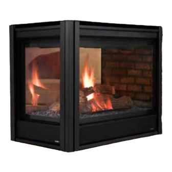
GDCH60 shown
CAUTION
Leave this manual with
•
party responsible for
use and operation.
• CAREFULLY SUPERVISE children in same room as
appliance.
• A l e r t c h i l d r e n a n d a d u l t s t o h a z a r d s o f h i g h
temperatures.
High temperatures may ignite clothing or other
ammable materials.
• Keep clothing, furniture, draperies and other combustibles
away.
This appliance has been supplied with an integral
barrier to prevent direct contact with the xed glass
panel. Do NOT operate the appliance with the barrier
removed.
Contact your dealer or Hearth & Home Technologies if the
barrier is not present or help is needed to properly install one.
In the Commonwealth of Massachusetts installation must
be performed by a licensed plumber or gas tter;
See Table of Contents for location of additional
Commonwealth of Massachusetts requirements.
Installation and service of this appliance should be performed
by quali ed personnel. Hearth & Home Technologies suggests
NFI certi ed or factory-trained professionals, or technicians
supervised by an NFI certi ed professional.
Owner's Manual
Installation and Operation
WARNING
HOT SURFACES!
Glass and other surfaces are hot during
operation and cool down.
Hot glass will cause burns.
• Do not touch glass until it is cooled
• NEVER allow children to touch glass
• Keep children away
1
Advertisement
Table of Contents

Related Manuals for Heatiator GDCH60 Series


Summary of Contents for Heatiator GDCH60 Series
- Page 1 Owner’s Manual Installation and Operation Models: GDCH60 Series GDST60 Series GDFL60 Series GDCR60 Series GDCL60 Series Direct Vent Gas Appliance GDCH60 shown CAUTION DO NOT DISCARD THIS MANUAL Read, understand and follow Leave this manual with • Important operating and •...
- Page 2 Read this manual before installing or operating this appliance. Please retain this owner’s manual for future reference. Congratulations Congratulations on selecting a Heatilator gas appliance—an The information contained in this owner’s manual, unless elegant and clean alternative to wood burning appliances. noted otherwise, applies to all models and gas control The Heatilator gas appliance you have selected is designed systems.
-
Page 3: Table Of Contents
Table of Contents Listing and Code Approvals 10 Electrical Information A. Appliance Certi cation ......4 A. -
Page 4: Listing And Code Approvals
Listing and Code Approvals A. Appliance Certi cation C. BTU Speci cations Caliber Multi-sided DV MODELS: GDCH60, GDST60, GDFL60, GDCR60, Standing Pilot GDCL60 Max/Min Input Rate (NG) 34,000/21,000 LABORATORY: Underwriters Laboratories, Inc. (UL) TYPE: Direct Vent Gas Appliance Ori ce Size (NG) .115 in./2.92 mm STANDARD: ANSI Z21.50b-2005/•CSA2.22b-2005 Max/Min Input Rate (LP) -
Page 5: Requirements For The Commonwealth Of Massachusetts
Inspection NOTE: The following requirements reference various The state or local gas inspector of the side wall horizontally Massachusetts and national codes not contained in this vented gas fueled equipment shall not approve the installa- document. tion unless, upon inspection, the inspector observes carbon monoxide detectors and signage installed in accordance G. -
Page 6: Getting Started
Getting Started A. Design and Installation Considerations C. Inspect the Appliance and Components Heatilator direct vent gas appliances are designed to op- erate with all combustion air siphoned from outside of the WARNING building and all exhaust gases expelled to the outside. No additional outside air source is required. -
Page 7: A. Select Appliance Location
Framing and Clearances Note: WARNING • Illustrations re ect typical installations and are FOR DESIGN PURPOSES ONLY. Fire Risk • Illustrations/diagrams are not drawn to scale. Provide adequate clearance: • Actual installation may vary due to individual design • Around air openings. preference. - Page 8 Appliance Locations for Catalina Marble & Shelf Package If you plan to use a Catalina Marble and Shelf package, refer to Figure 3.2 dimensions to determine appliance location. Refer to the Catalina Installation Instructions included with the kit for assembly and installation. 34-1/2 in.
-
Page 9: Construct The Appliance Chase
B. Construct the Appliance Chase C. Mantel Projections A chase is a vertical boxlike structure built to enclose the gas appliance and/or its vent system. Vertical vents that run on the outside of a building may be, but are not required to be, installed inside a chase. -
Page 10: Clearances
1/2 in. 1/2 in. (13 mm) (13 mm) (13 mm) GDCL/CR60 SERIES GDCH60 SERIES (GDCL60 SHOWN) Figure 3.4 Clearances to Combustibles Note: When installing these appliances, do not cover or frame in the lower panels of the appliance. This will interfere with proper operation of glass assemblies and access to the control panel. -
Page 11: Termination Locations
Termination Locations A. Vent Termination Minimum Clearances Measure vertical clearances from this surface Figure 4.2 speci es minimum vent heights for various pitched roofs. WARNING Fire Risk Explosion Risk Maintain vent clearance to combustibles as speci ed. • Do not pack air space with insulation or other materials. - Page 12 Horizontal overhang 20 in. 24 in. min. (508 mm) (610 mm) Vertical Lowest wall Discharge Opening Termination Storm Collar Roof Flashing Roof Pitch is X / 12 H (min.) - Minimum height from roof to lowest discharge opening. Roof Pitch H (Min.) Ft.
- Page 13 Fixed Openable Fixed Closed Closed GAS METER V TERMINATION CAP AIR SUPPLY INLET RESTRICTION ZONE (TERMINATION NOT ALLOWED) Measure vertical clearances from this surface Electrical Service Alcove Clearances Measure horizontal clearances Clearances to Electrical Service from this surface. Dimension Descriptions 6”...
-
Page 14: Vent Information And Diagrams
Vent Information and Diagrams A. Vent Table Key The abbreviations listed in this vent table key are used in the vent diagrams. Symbol Description First section (closest to appliance) of vertical length Vertical Second section of vertical length First section (closest to appliance) of horizontal length Second section of horizontal length 8-1/2 in. -
Page 15: Vent Diagrams
D. Vent Diagrams WARNING Fire Risk Explosion Risk Do NOT pack insulation or other combustibles between restops. • ALWAYS maintain speci ed clearances around venting and restop systems. • Install restops as speci ed. Failure to keep insulation or other material away from vent pipe may cause re. The rst 90°... - Page 16 Top Vent—Horizontal Termination—Two 45° Elbows Installation requirements to replace the rst 90° elbow with two 45° elbows: 4 ft min. (1.22 m) 25 ft max. (7.62 m) Figure 5.4 Minimum Installation Requirements for Two 45° Elbows-Top Vent-Horizontal Termination Top Vent—Horizontal Termination—Three Vertical Elbows See Figure 5.6 for information about installing elbows horizontally.
- Page 17 Top Vent—Horizontal Termination—Two or Three Elbows You may use a maximum of three 90° elbows (or six 45° elbows) in any vent con guration, Some may be installed hori- zontally. Note: Subtract 3 ft (914 mm) from the total horizontal measurement for each 90°...
- Page 18 Top Vent—Vertical Termination—No Elbows 12 ft (3.66 m) min. 60 ft (18.29 m) max. Figure 5.7 Vertical Termination - No Elbows Top Vent—Vertical Termination—Two Elbows 12 ft (3.66 m) min. 60 ft (18.29 m) max. Maximum horizontal run is 100% of vertical, but cannot exceed 26 ft (7.92 m) Figure 5.8...
- Page 19 Top Vent—Vertical Termination—Three Elbows Note: Subtract 3 ft (914 mm) from the total horizontal measurement for each 90° elbow installed horizontally. Subtract 1-1/2 ft (456 mm) from the total horizontal measurement for each 45° elbow installed horizontally. Maximum horizontal run is 100% of vertical, but cannot exceed 26 ft (7.92 m) 12 ft (3.66 m) min.
- Page 20 Rear Vent—Horizontal Termination—One 45° Elbow 18 in. (457 mm) max. Figure 5.11 Horizontal Termination - One 45° Elbow Rear Vent—Horizontal Termination—Two Elbows Table 5.4 Gas Appliance 2-Elbow Total Vert Total Horiz Parameters V Min. Multi-Sided 12 in./305 mm 3 ft/.91 m 12 in./305 mm 12 in./305 mm 4 ft/1.22 m 24 in./610 mm 12 in./305 mm...
- Page 21 Rear Vent—Horizontal Termination—Three Elbows Note: Subtract 3 ft (914 mm) from the total horizontal measurement for each 90° elbow installed horizontally. Subtract 1-1/2 ft (456 mm) from the total horizontal measurement for each 45° elbow installed horizontally. Installed Horizontally Table 5.5 Gas Appliance 3-Elbow Total Vert...
- Page 22 Rear Vent—Vertical Termination—One Elbow 0 min. 6 ft (1.83 m) max. 12 ft (3.66 m) min. 60 ft (18.29 m) max. Figure 5.14 Vertical Termination - One Elbow Rear Vent—Vertical Termination—Two Elbows Note: Subtract 3 ft (914 mm) from the total horizontal measurement for each 90°...
- Page 23 Rear Vent—Vertical Termination—Three Vertical Elbows 0 min. 6 ft (1.83 m) max. 12 ft (3.66 m) min. 60 ft (18.29 m) max. Maximum horizontal run is 100% of vertical, but can- not exceed 26 ft (7.92 m). Figure 5.16 Vertical Termination - Three Vertical Elbows Heatilator •...
-
Page 24: Vent Clearances And Framing
Vent Clearances and Framing A. Pipe Clearances to Combustibles WARNING Note: Heat shields MUST overlap by a minimum of 1-1/2 in. (38 mm). The heat shield is designed to be used on a wall Fire Risk 4 in. to 7-1/4 in. (102 mm to 184 mm) thick. If wall thickness is less than 4 in. -
Page 25: Install The Ceiling Firestop
Install the Ceiling Firestop • Frame an opening 10 in. by 10 in. whenever the vent system penetrates a ceiling/ oor (see Figure 6.4). • Frame the area with the same sized lumber as used in ceiling/ oor joist. Attic Above •... -
Page 26: Install Attic Insulation Shield
D. Install Attic Insulation Shield WARNING Fire Risk Keep loose materials or blown insulation Laser-etched from touching the vent pipe. cut lines Bend all tabs inward • National building codes recommend using Insert 3 90° to maintain screws attic shield to keep loose materials/blown clearance and insulation from contacting vent. -
Page 27: Appliance Preparation
Appliance Preparation • Remove four screws holding outer collar to appliance top. CAUTION See Figure 7.2. Remove outer collar. Sharp Edges • Wear protective gloves and safety glasses during installation. A. Appliance Placement This appliance may be placed on a smooth combustible or noncombustible, continuous, at surface. - Page 28 • Remove four screws holding outer cover to appliance • Place outer collar on rear of appliance and replace four back. See Figure 7.5. Remove outer cover (be sure to screws to hold collar in place. See Figure 7.8. Make sure remove the insulation as well).
-
Page 29: Securing And Leveling The Appliance
• Place outer cover plate on appliance top and replace four • Locate outer shell cover removed in the fourth step screws to hold outer cover plate in place. See Figure 7.11. (Figure 7.4). Place the cover on top of appliance. Replace Make sure insulation is replaced along with cover plate. -
Page 30: Installing Vent Pipe
Installing Vent Pipe A. Assemble Vent Sections WARNING Fire Risk WARNING Explosion Risk Fire Risk If slip section seals are broken during the removal of the termination cap, gas will leak Explosion Risk. and a re or explosion may occur. Do not mix pipe, ttings or joining methods do not break silicone seals on slip sections. - Page 31 Make sure the seams are not aligned to prevent unintentional disconnection. CORRECT INCORRECT Figure 8.4 Seams Figure 8.5 MI Sections For 90° and 45° elbows that are changing the vent direction from horizontal to vertical, one screw minimum should be put in the outer ue at the horizontal elbow joint to prevent the elbow from rotating.
-
Page 32: Disassemble Vent Sections
Secure the Vent Sections Vertical sections of pipe must be supported every 8 ft after the 25 ft maximum unsupported rise. The vent support or plumber’s strap (spaced 120° apart) may be used to do this (see Figures 8.8 and 8.9). Horizontal sections of vent must be supported every 5 ft with a vent support or plumber’s strap. -
Page 33: Install The Heat Shield And Horizontal Termination Cap
C. Install the Heat Shield and Horizontal Termination Cap Heat Shield Requirements for Horizontal Termination WARNING For all horizontally vented appliances, a heat shield MUST be placed 1 in. (25 mm) above the top of the vent between Fire Risk the wall shield restop and the base of the termination cap. - Page 34 Install the Horizontal Termination Cap WARNING Vent termination must not be recessed in the wall. Siding may be brought to the edge of the cap base. Burn Risk Flash and seal as appropriate for siding material at outside • Local codes may require installation of a edges of cap cap shield to prevent anything or anyone from touching the hot cap.
-
Page 35: Install Roof Flashing And Vertical Termination Cap
D. Install Roof Flashing and Vertical Termination Cap To install roof ashing see Figures 8.13 and 8.14. Caulk the gap between the roof ashing and the outside di- ameter of the pipe. Caulk the perimeter of the ashing where For installation of vertical termination cap see minimum vent it contacts the roof surface. -
Page 36: Assemble And Install Storm Collar
E. Assemble and Install Storm Collar CAUTION Sharp Edges! • Wear protective gloves and safety glasses during installation. Connect both halves of the storm collar with two screws (see Figure 8.16). Wrap the storm collar around the exposed pipe section and align brackets. -
Page 37: Gas Information
Gas Information A. Fuel Conversion C. Gas Connection Before making gas connections ensure appliance being in- Note: Have the gas supply line installed in accordance stalled is compatible with the available gas type. with local building codes, if any. If not, follow ANSI Any natural or propane gas conversions necessary to meet 223.1. -
Page 38: High Altitude Installations
D. High Altitude Installations WARNING U.L. listed gas appliances are tested and approved without requiring changes for elevations from 0 to 2000 ft in the USA Fire Risk and Canada. Explosion Risk When installing this appliance at an elevation above 2000 ft, •... -
Page 39: Electrical Information
Electrical Information A. Recommendation for Wire B. Connecting to the Appliance This appliance requires 110-120 VAC to be wired to the junc- tion box either for use of optional accessories (standing pilot WARNING ignition) or for proper operation of the appliance (Intelli re ignition). -
Page 40: Standing Pilot Ignition System Wiring
Optional SPST Wall Switch Battery Ignitor Flame Pack Optional Remote Sensor Control Pilot Assembly Junction GRN* Adapter * GRN wire only for use with optional wall switch WSK-MLT Valve Figure 10.2 Intelli re Pilot Ignition (IPI) Wiring Diagram D. Standing Pilot Ignition System Wiring CAUTION •... -
Page 41: Junction Box Installation
E. Junction Box Installation • Remove the burner assembly by unscrewing the four screws holding it in place. See Figure 10.5. If the box will not be wired at the time of appliance instal- lation, assemble the receptacle and cover to the box and install on the inside of the appliance. - Page 42 • • Take the light base assembly and position it into the Remove the halogen bulbs from the packaging and screw rectangular hole. Using the screws removed in the them into the light base. See Figure 10.10. Once the previous step, attach the light base to the valve plate. bulbs are in place, clean the surface of the bulbs with a See Figure 10.8.
-
Page 43: Finishing
Finishing A. Mantel Projections B. Facing Material Figure 11.1 shows the minimum vertical and corresponding When installing these appliances, do not cover or frame in maximum horizontal dimensions of appliance mantels or the lower panels of the appliance. This will interfere with other combustible projections above the top front edge of proper operation of glass assemblies and access to the con- the appliance. -
Page 44: Appliance Setup
Appliance Setup A. Remove Glass Assembly • Rock Wool: Place a small amount of 1/2 in. diameter pieces (dime size) on burner pan. Do not cover holes in See Section 12.G. burner pan. See Figure 12.3 B. Remove the Shipping Materials •... -
Page 45: Log Assembly
F. Log Assembly Replacing Glass Panel Assembly • Place glass panel on the lower access latches and rotate The log set should look similar to that in Figure 12.4. the upper portion into place. Engage the top then the lower latches. -
Page 46: Grilles And Trim
I. Grilles and Trim K. Air Shutter Setting • Install optional trim kits and surrounds. This appliance has an adjustable air shutter (which controls • Non-combustible materials can be used to cover gap the primary air mixture) that can be accessed from under the valve compartment located under the rebox assembly (see between sheet rock and appliance. -
Page 47: Operating Instructions
Operating Instructions A. Before Lighting Appliance WARNING Before lighting this appliance, determine if it has a stand- ing pilot or Intelli re ignition system by opening the control HOT SURFACES! access panel to view wiring system and gas valve. If this Glass and other surfaces are hot during appliance has a red or black ignitor button (See Figure 10.1) operation and cool down. -
Page 48: Lighting The Appliance
B. Lighting the Appliance Intelli re Ignition Heatilator • Caliber Multi-Sided Direct Vent • 4002-079 Rev K • 11/07... -
Page 49: Standing Pilot Ignition
Standing Pilot Ignition Heatilator • Caliber Multi-Sided Direct Vent • 4002-079 Rev K • 11/07... -
Page 50: After The Appliance Is Lit
C. After the Appliance is Lit CAUTION Initial Break-in Procedure When you light the appliance, you may notice that it pro- • Prevent accidental appliance operation when not duces heat which does have an associated odor or smell. If attended. you feel this odor is excessive it may require the initial three •... -
Page 51: Troubleshooting
Troubleshooting With proper installation, operation and maintenance your gas appliance will provide years of trouble-free service. If you do experience a problem, this troubleshooting guide will assist a quali ed service person in the diagnosis of a problem and the corrective action to be taken. -
Page 52: Corrective Actions
Symptom Possible Causes Corrective Actions Frequent pilot outage Pilot ame may be too Clean and adjust the pilot ame for maximum ame impingement on problem. high, too low, or blowing thermocouple. Follow lighting instructions carefully. (high), causing pilot safety to drop out. The pilot and main No LP in the tank. -
Page 53: Intelli Re Ignition System
B. Intelli re Ignition System Symptom Possible Causes Corrective Actions The ignitor/module makes Incorrect wiring. Verify “S” wire (white) for sensor and “I” wire (orange) for ignitor are noise, but no spark. connected to the correct terminals on the module and the pilot assembly. Reversed wires at the module may cause the system to make a sparking noise, but the spark may not be present at pilot hood. - Page 54 Symptom Possible Causes Corrective Actions Pilot sparks, but pilot will Correct gas supply. Verify that incoming gas line ball valve is “open”. Verify that inlet pressure not light. reading is within acceptable limits, inlet pressure must not exceed 14 in. w.c. Ignitor gap is too large.
-
Page 55: Maintaining And Servicing The Appliance
Maintaining and Servicing the Appliance Although the frequency of appliance servicing and maintenance will depend on use and the type of installation, a quali ed service technician should perform an appliance check-up at the beginning of each heating season. WARNING CAUTION Risk of injury or property damage Handle glass assembly with care. -
Page 56: Maintenance Tasks
Maintenance and Service Tasks: Inspect Maintenance Tasks Access condition of screen and replace as necessary. Recommend addition of screen if Doors, surrounds and fronts one is not present. Inspect for scratches, dents or other damage and repair as necessary. Verify no obstructions to air ow through the louvers. Verify proper clearance to combustible household objects is maintained. -
Page 57: Reference Materials
Reference Materials A. Appliance Dimension Diagram Dimensions are actual appliance dimensions. Use for reference only. For framing dimensions and clearances refer to Sec- tion 3. 24 in. (610 mm) 40 in. (1016 mm) 7 in. 7 in. 38-1/2 in. 40-5/8 in. (178 mm) (178 mm) (978 mm) - Page 58 24 in. (610 mm) 12 in. 40 in. (305 mm) (1016 mm) 38-1/2 in. 40-5/8 in. (978 mm) (1032 mm) 29 in. (737 mm) 34-1/4 in. 2-7/8 in. (870 mm) 2-7/8 in. (73 mm) (73 mm) 36 in. 19-7/8 in. 2-7/8 in.
-
Page 59: Vent Components Diagrams
B. Vent Components Diagrams Components Description DVP4 4 in. length Vent Pipe DVP6 6 in. length Vent Pipe DVP12 12 in. length Vent Pipe DVP24 24 in. length Vent Pipe DVP6A 3 in. - 6 in. Slip Section Vent Pipe (to be used with another piece of pipe) DVP36 36 in. - Page 60 Pipe Effective Length 4-7/8 in. DVP4 4 in. (102 mm) (124 mm) DVP6 6 in. (152 mm) 10-1/2 in. DVP12 12 in. (305 mm) 45° (267 mm) Effective DVP24 24 in. (610 mm) Length DVP36 36 in. (914 mm) DVP48 48 in.
- Page 61 31 in. (787 mm) 24-5/8 in. 13-1/4 in. (625 mm) (367 mm) 27-1/2 in. 24-5/8 in. 13-1/4 in. (698 mm) (625 mm) (367 mm) RF6M RF12M Roof Flashing Multi-pak Roof Flashing Multi-pak 13-3/4 in. 5 in. 11-7/8 in. 5 in. (349 mm) (127 mm) (302 mm)
- Page 62 7-3/8 in. (187 mm) 1-1/2 in. (38 mm) 17-3/4 in. 14 in. (451 mm) (356 mm) PVK-80 (For use with IPI and DSI appliances only.) 12 in. (305 mm) 3-7/8 in. (98 mm) DVP-TB1 Basement Vent Cap 10-1/2 in. (267 mm) DVP-TV Vertical Termination Cap 7-1/4 in.
- Page 63 Note: Heat shields MUST overlap by a minimum of 1-1/2 in. (38 mm). The heat shield is designed to be used on a wall 4 in. to 7-1/4 in. (102 mm to 184 mm) thick. If wall thickness is less than 4 in. (102 mm) the existing heat shields must be field trimmed.
- Page 64 Fillers DVP-TRAP to DVP-HPC Side Filler Kit 8-1/8 in. 13 in. (206 mm) (330 mm) 15 in. (381 mm) DVP-HRC-SS Effective Length 5-1/2 in. 8-3/8 in. 5-3/4 to 8-3/8 in. 140 mm 213 mm 146 to 213 mm 3° 87° 10-1/2 in.
- Page 65 Heatilator • Caliber Multi-Sided Direct Vent • 4002-079 Rev K • 11/07...
-
Page 66: Optional Components
D. Optional Components GDCH60 Optional Accessories (shipped separately) GDFL60 Optional Accessories (shipped separately) RCTS-MLT-HTL Remote Control Kit (SIT Valve only) RCTS-MLT-HTL Remote Control Kit (SIT Valve only) RCT-MLT-HTL Remote Control Kit (Robertshaw Valve only) RCT-MLT-HTL Remote Control Kit (Robertshaw Valve only) RC-BATT-HTL Battery operated remote control RC-SMART-HTL Remote control (requires 110v or prewiring) -
Page 67: Limited Lifetime Warranty
E. Limited Lifetime Warranty Gas Appliance (Fireplace) Limited Lifetime Warranty HEARTH & HOME TECHNOLOGIES INC. (“HHT”) extends the following warranty for HEATILATOR appliances installed in the United States of America or Canada (the "Appliance"). Dealers and employees of HHT have no authority to make any warranty or authorize any remedies in addition to or inconsistent with the terms of this warranty. -
Page 68: Contact Information
F. Contact Information Hearth & Home Technologies Inc. 1915 W. Saunders Street Mt. Pleasant, Iowa 52641 www.heatilator.com Please contact your Heatilator dealer with any questions or concerns. For the number of your nearest Heatilator dealer, please visit www.heatilator.com. - NOTES - CAUTION DO NOT DISCARD THIS MANUAL Read, understand...
Need help?
Do you have a question about the GDCH60 Series and is the answer not in the manual?
Questions and answers