
Related Manuals for Hayter 455E


Summary of Contents for Hayter 455E
- Page 1 21in Heavy-Duty Walk-Behind Rotary Mower Code 455E Serial No. 310000001 Manual Part No. 3364-824 Rev A...
-
Page 2: Table Of Contents
Contents Introduction Introduction..............2 Safety ................3 This rotary-blade, walk-behind lawn mower is General Lawn Mower Safety ......... 3 intended to be used by residential homeowners Sound Pressure............. 5 or professional, hired operators. It is designed Sound Power ............5 primarily for cutting grass on well-maintained lawns Vibration, Hand/arm ........... -
Page 3: Safety
Safety Preparing the Engine.......... 28 General Information .......... 28 Removing the Lawn Mower from Storage.... 28 Improperly using or maintaining this mower can Troubleshooting............29 result in injury. To reduce the potential for injury, comply with these safety instructions. This mower was designed and tested for reasonably safe service;... -
Page 4: Maintenance And Storage
• If petrol is spilled, do not attempt to start the engine – Do not mow excessively steep slopes. but move the mower away from the area of spillage – Exercise extreme caution when on slopes. and avoid creating any source of ignition until petrol –... -
Page 5: Sound Pressure
• Allow the engine to cool before storing in any enclosure. • To reduce the fire hazard, keep the engine, silencer, battery compartment and petrol storage are free of grass, leaves, or excessive grease. • Check grass bag components and the discharge guard frequently and replace with manufacturer’s recommended parts, when necessary. -
Page 6: Safety And Instructional Decals
Safety and Instructional Decals Safety decals and instructions are easily visible to the operator and are located near any area of potential danger. Replace any decal that is damaged or lost. 110-2115 1. Read the Operator’s Manual. 3. To engage the traction control, lift the lower bail upward. 2. -
Page 7: Setup
Setup Loose Parts Use the chart below to verify that all parts have been shipped. Procedure Description Qty. Handle Bolt (5/16 x 7/8 inch) Bolt (5/16 x 1-1/2 inches) Install the handle. Washer Locknut (5/16 inch) Cable tie Self-tapping screw Install the fuel tank and fuel line. -
Page 8: Filling The Crankcase With Oil
Installing the Fuel Tank and the Fuel Line Parts needed for this procedure: Self-tapping screw Fuel tank Procedure Figure 5 1. Slide the end of the fuel line onto the elbow fitting 1. Plastic clip (2) (Figure 4). 4. Secure the bottom of the fuel tank to the fuel tank bracket by installing the self-tapping screws from the bottom. -
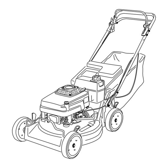
Page 9: Product Overview
4. Stop Specifications Figure 6 Model Weight Length Width Height 1. Handle 8. Oil fill/dipstick (not shown) 455E 124 lb 59 in 23 in 38 in 2. Blade control bar 9. Air filter (56 kg) (149 cm) (57 cm) (97 cm) 3. -
Page 10: Operation
Operation Note: When the crankcase is empty, pour about 3/4 of the crankcase capacity of oil in the crankcase, then follow the procedure in this section. Note: Determine the left and right sides of the machine from the normal operating position. 1. -
Page 11: Filling The Fuel Tank
Filling the Fuel Tank For best results, use clean, fresh, lead-free petrol with In certain conditions, petrol is extremely an octane rating of 87 or higher. To ensure freshness, flammable and highly explosive. A fire or purchase only the quantity of petrol that you expect to explosion from petrol can burn you and others use in 30 days. -
Page 12: Starting The Engine
Operating the Blade Important: Do not fill the tank more than 1/4 inch (6 mm) from the top of the tank because the petrol must have room to expand. Engaging the Blade 4. Install the fuel tank cap and wipe up any spilled When you start your engine, the blade does not turn. -
Page 13: Operating The Traction Drive
Disengaging the Blade Disengaging the Traction Drive Release the blade control bar. Release the traction control bar. Important: When you release the blade control Checking the Blade Brake bar, the blade should stop within 3 seconds. If it does not stop properly, stop using your mower Clutch immediately and contact an Authorized Service Dealer. -
Page 14: Using The Grass Bag
Adjusting the cutting height levers could bring your hands into contact with a moving blade and result in serious injury. • Stop the engine and wait for all movement to stop before adjusting the cutting height. • Do not put your fingers under the housing when adjusting the cutting height. -
Page 15: Operating Tips
Mowing with the Grass Bag Operating a mower with its engine running at a speed greater than the factory setting can A worn grass bag could allow small stones cause the mower to throw a part of the blade or and other similar debris to be thrown in the engine into the operator’s or bystander’s area operator’s or bystander’s direction and result in... - Page 16 • For light leaf coverage, set all the wheels at the same cutting height setting. • If there are more than 5 inches (12.7 cm) of leaves on the lawn, set the front cutting height 1 or 2 notches higher than the rear cutting height. This makes it easier to feed the leaves under the mower housing.
-
Page 17: Maintenance
Maintenance Note: Determine the left and right sides of the machine from the normal operating position. Recommended Maintenance Schedule(s) Maintenance Service Maintenance Procedure Interval • Change the engine oil. After the first 8 hours • Check the engine oil level. •... -
Page 18: Lubricating The Gear Case
Lubricating the Gear Case Engine Maintenance Service Interval: Every 100 hours Servicing the Air Filter After every 100 operating hours, grease the gear case. Service Interval: Every 25 hours—Clean the foam 1. Remove the grass bag. pre-cleaner (more frequently in dusty 2. -
Page 19: Changing The Engine Oil
6. Remove the foam pre-cleaner and wash it with a 10. Fill the crankcase to the Full line on the dipstick with mild detergent and water, then blot it dry. fresh oil. Refer to the Filling the Crankcase with Oil. 7. -
Page 20: Servicing The Spark Plug
Figure 27 1. Center electrode insulator Figure 26 2. Side electrode 3. Air gap (not to scale) 1. Gasket 6. Install the spark plug and the gasket seal. 8. Install the new filter and hand tighten it 2/3 turn only. 7. -
Page 21: Fuel System Maintenance
Fuel System Drive System Maintenance Maintenance Adjusting the Self-propel Drive Emptying the Fuel Tank and Cleaning the Fuel Filter If the mower does not self-propel or has a tendency to creep forward when the control bar is more than 1-1/2 Service Interval: Yearly inches (3.8 cm) from the handle, adjust the self-propel drive. -
Page 22: Servicing The Wheels
8. Move the lower anchor bracket up one hole (Figure 30). 9. Repeat steps 1 through 3 to adjust the control bar. Note: When you install a new belt, move the lower anchor bracket to its original factory position, which is indicated by the notches next to the holes in the bracket (Figure 30). -
Page 23: Controls System Maintenance
Controls System halves together. Mount the screws or bolts in the opposing holes (Figure 31). Maintenance 5. Check the alignment of all parts and tighten the screws, alternating from side to side for a uniform fit, until the wheel halves are drawn together (Figure 31). Adjusting the Blade Brake 6. - Page 24 Do not overtighten the blade brake cable. Overtightening the blade brake cable could prevent the blade brake from contacting the brake drum when you release the control bar. If the blade brake does not contact the brake drum, the blade will not stop rotating, which could cause serious personal injury.
-
Page 25: Blade Maintenance
Blade Maintenance Maintaining the Cutting Blade Always mow with a sharp blade. A sharp blade cuts cleanly and without tearing or shredding the grass blades. Complete the following procedure before inspecting, removing, or installing the blade: Figure 36 1. Stop the engine and wait for all moving parts to stop. 1. -
Page 26: Cleaning
Balancing the Blade Cleaning 1. Check the balance of the blade by placing the center hole of the blade over a nail or screwdriver shank Cleaning under the Mower clamped horizontally in a vise (Figure 38). Housing To ensure the best performance, keep the underside of the mower housing clean. -
Page 27: Cleaning The Blade Brake Clutch Shield
Tipping the mower may cause the fuel to leak from the carburetor or the fuel tank. Petrol is extremely flammable, highly explosive, and, under certain conditions, can cause personal injury or property damage. Avoid fuel spills by running the engine dry or by removing the petrol with a hand pump;... -
Page 28: Storage
Storage 2. Clean any dirt and chaff from the cylinder, cylinder head fins, and blower housing. To prepare the mower for off-season storage, perform 3. Remove grass clippings, dirt, and grime from the the recommended maintenance procedures. Refer to external parts of the engine, the shrouding, and the Maintenance. -
Page 29: Troubleshooting
Troubleshooting Problem Possible Cause Corrective Action Engine does not start 1. The fuel tank is empty or the fuel 1. Drain and/or fill the fuel tank with fresh system contains stale fuel. petrol. If the problem persists, contact an Authorized Service Dealer. 2. - Page 30 Notes:...
- Page 31 LIMITED WARRANTY Hayter Limited warrants to the original user/purchaser that this unit shall be free from defects in material and workmanship under normal use and service for a period of one year from the date of purchase. The manufacturers of the engine furnish their own warranty and services are provided through their authorised network (Refer to "Engine Warranty Statement").
Need help?
Do you have a question about the 455E and is the answer not in the manual?
Questions and answers