Hayter HARRIER 41 Owner's Handbook Manual
Hide thumbs
Also See for HARRIER 41:
- Owner's handbook manual (47 pages) ,
- Owner's handbook manual (20 pages) ,
- Owner's handbook manual (24 pages)

Subscribe to Our Youtube Channel
Related Manuals for Hayter HARRIER 41


Summary of Contents for Hayter HARRIER 41
- Page 1 Harrier CODE 410A 411A 412A (Push) (Auto Drive) (Electric Start Variable Speed) OWNER'S HANDBOOK (English Version) FROM SERIAL NO: 410A001001, 411A001001, 412A001001 HANDBOOK: 410066 (REV .2.) ISSUE 08.07.02...
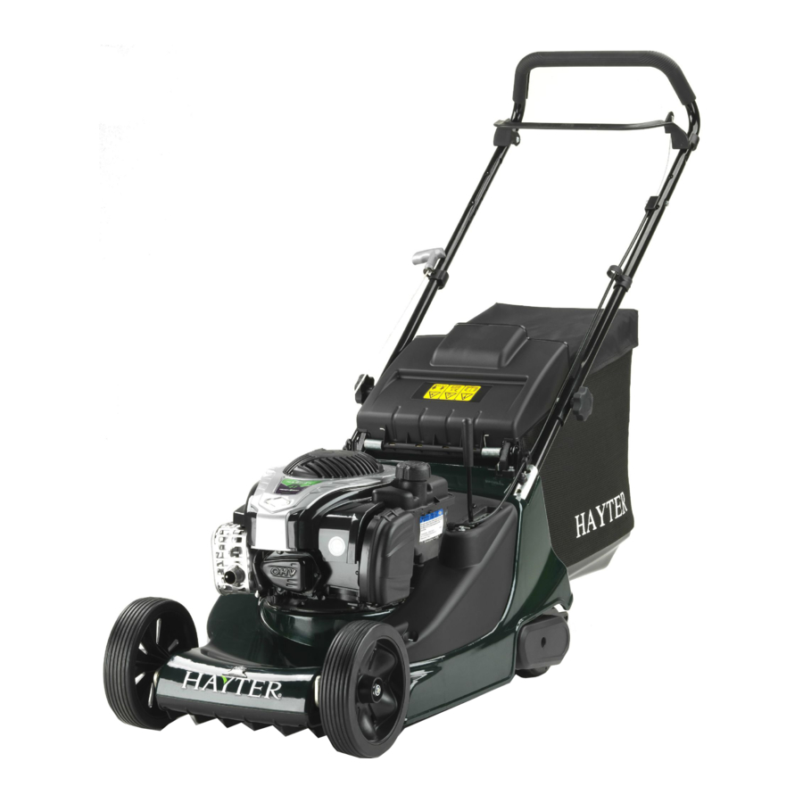
- Page 2 MAIN FEATURES /SPECIFICATIONS Main Features Air Cleaner Fuel Filler Cap Oil Filler Cap and Dipstick Handlebar Securing Knob Engine Start-Grip Throttle Control. Engine Stop lever. Handlebar Ground Drive Clutch Lever (411 & 412 Only) 10 Variable Speed Control (412 Only) 11 Grassbag Assembly 12 Height of Cut Adjuster 13 Serial No.
-
Page 3: Table Of Contents
CONTENTS 1.2 Main Features/Specifications 1.19 - 1.25 Mower Maintenance 1.19 - Engine 1.3 Contents 1.19 - Throttle Cable Adjustment 1.19 - Carburettor Adjustments 1.4 Introduction 1.20 - Oil Service 1.20 - Air Cleaner Service 1.5 Warranty 1.21 - Spark Plug Service 1.21 - Keeping Engine Clean 1.6 - 1.9 Safety Precautions... -
Page 4: Introduction
INTRODUCTION Thank you for purchasing a Hayter mower. The following pages are designed to help you gain safe and efficient service from your mower. IMPORTANT: This ‘Owners Handbook’ should be regarded as part of the mower as it gives essential information regarding mower safety, operation, maintenance and specifications. Read and understand this handbook prior to operating your mower for the first time. -
Page 5: Warranty
This warranty does not apply to any unit that has been tampered with, altered, misused, abused or used for hire, and will become invalid if non genuine Hayter parts are fitted. This warranty does not cover minor mechanical adjustments unless they are due to defective material or workmanship. -
Page 6: 1.9 Safety Precautions
SAFETY PRECAUTIONS Safety Alert Symbol This safety alert symbol indicates important safety messages. When you see this symbol be alert to the possibility of injury. Carefully read the following and inform others. Your mower is perfectly safe if used correctly. Failure to observe the following precautions may result in serious injury. - Page 7 A damaged cutterblade must be replaced immedi- ately with a genuine Hayter replacement part Operation Do not operate the engine in a confined space where exhaust fumes (carbon monoxide) can collect.
-
Page 8: Stop The Engine
SAFETY PRECAUTIONS Operation Do not tilt the mower when starting the engine. Do not put hands or feet near or under rotating parts. Never pick up or carry the mower while the engine is running. Never lift the rear deflector while the engine is running. Never touch the exhaust/exhaust guard or cooling fins when the engine is hot. -
Page 9: Safety Symbols
Wear strong work gloves when removing and reassembling the cut- terblade. Always replace worn or faulty parts with genuine Hayter parts. Safety Symbols Danger of being hit by thrown Safety Alert - Be aware to the Danger of severing toes or fin- possibility of injury. -
Page 10: Assembling The Mower
ASSEMBLING THE MOWER Delivery Checklist Remove the mower from the packaging and check that the following items have been supplied correctly. If any items are missing contact, your local Hayter dealer. 1. Engine Handbook. 2. Warranty Reg. Card. 3. Grassbag. -
Page 11: Prevent Engine Damage
STARTING MOWER BEFORE Prevent Engine Damage To prevent engine damage the engine is shipped without oil or petrol. The engine must be filled with the correct grade of oil and petrol before starting the engine. Oil Type Always use high quality detergent oil classified SAE 30 oil. Never use additives with recommended oil. -
Page 12: 1.15 Operating The Mower
OPERATING THE MOWER Controls Operate all control levers several times and ensure that the cables move freely. Check that the engine stop and ground drive clutch levers return freely to their rest position when released. Whilst operating the engine throttle mechanism slight resistance should be felt when moving the lever to the ‘choke’... -
Page 13: Electric Start
OPERATING MOWER Electric Start (412 Only) - Stand behind the mower and hold the handlebar together with the engine stop lever. Turn the ignition key in a clockwise direc- tion and hold in position to crank the engine. When the engine starts release the key and move the throttle to the fast position after starting a cold engine. -
Page 14: Slopes
OPERATING THE MOWER Slopes To prevent engine damage do not use the mower on slopes greater than 20 degrees. Height of Cut Move the height of cut lever sideways to disengage it from the locking notch, then push forwards to lower or pull backwards to raise the height of cut. -
Page 15: Without Grass Collection
OPERATING MOWER Without Grass Collection Remove the grassbag and operate the mower with the rear deflector in the closed position. Heavy Growth Areas of heavy growth should be mown without collecting the clip- pings. If collection is required, first mow the area without the grass- bag at the maximum height of cut setting. -
Page 16: Lawn Care Calendar
LAWN CARE CALENDAR To be used as a guide only. January There is very little work to do this month apart from brushing away leaves. Keep off the grass if frozen or waterlogged. February Rake the grass thoroughly. Spike the lawn to aerate and stimulate soil organisms and root growth and apply lawn sand if necessary. -
Page 17: Lawn Stripes
LAWN CARE CALENDAR August Keep mowing regularly and watering as necessary. Fill any cracks caused by drought with a mixture of sharp sand and soil. In dry weath- er conditions leave the grass longer to help retain ground moisture. September Raise the height of cut to allow the grass to thicken and protect the roots from the winter frost and snow. -
Page 18: Maintenance Schedule
MAINTENANCE SCHEDULE After the very first hour check clutch adjustment. See page 1.22. After the very first five hours change the engine oil. Follow the hourly or calendar intervals, whichever occurs first. More frequent service will be required if working for prolonged periods under dusty, dry conditions, or when airborne debris is present or after extensive operation cutting tall, dry grass. -
Page 19: 1.25 Mower Maintenance - Engine
MOWER MAINTENANCE To prevent accidents stop the engine disconnect the spark plug lead before attempting to carry out maintenance procedures on the mower. Engine Air Filter Fuel Cap Start Grip Oil Cap/ Dipstick Exhaust Guard Spark Plug / Lead Throttle Cable Adjustment Loosen casing clamp screw (1) and move the governor lever (2) in the direction of screw (1) as far as posible. -
Page 20: Oil Service
MAINTENANCE MOWER Oil Service Check the oil level daily before starting the engine and ensure that the correct oil level is maintained. Refer to-‘Before Starting the Mower’ for oil checking and filling instructions. Change the engine oil after the first 5 hours of operation and thereafter according to the ‘Maintenance Schedule’:- 1. -
Page 21: Spark Plug Service
MOWER MAINTENANCE Spark Plug Service Use only Briggs & Stratton spark tester (1) to check for a spark as shown in the diagram. Replace the spark plug every 100 hours or every season, whichever occurs first. A spark plug wrench is available from any authorised Briggs &... -
Page 22: Deck Housing
MOWER MAINTENANCE Deck Housing Remove grass debris from the top and underside of the deck housing immediately after use. Fertilisers and top dressings are particularly corrosive. Thoroughly clean the mower deck immediately after use on treat- ed grass and store well away from corrosive materials. Securing Nuts &... -
Page 23: Lubrication
DO NOT rotate tools towards the cut- ting edges to avoid the risk of injury should the tool slip. ALWAYS use genuine Hayter replacement parts. The condition of the cutterblade and its mounting arrangement should be checked regularly for signs of wear or damage. Ensure that the cut- terblade is not bent or cracked. -
Page 24: Cutterblade Assembly
MOWER MAINTENANCE Cutterblade Assembly Assemble the cutterblade with the turned up edges facing towards the engine. Secure the cutterblade using the bolt (1), spring washer (2), and distance piece (3) and tighten to a torque of 54Nm Cutterblade Sharpening 30°-45° A slightly worn cutterblade may be re-sharpened. -
Page 25: Storage
MOWER MAINTENANCE Storage To store the handlebar unscrew the 2 small securing knobs sufficient- ly to allow it to be pivoted forwards to rest against the mower. Take care to ensure that the control cables do not become snagged at the pivot point and depress the engine stop lever to prevent it being dam- aged through contact with the engine spark plug. -
Page 26: Battery Charging
MOWER MAINTENANCE Battery charging (412 only) - PREVENT ACCIDENTS: ALWAYS charge the bat- tery in a well ventilated area. NEVER charge the battery near naked flames or direct heat. ALWAYS switch off the mains electricity supply before discon- necting the charger from the battery. ALWAYS use the battery charger supplied with the mower. -
Page 27: 1.28 Trouble Shooting
TROUBLE SHOOTING PROBLEM POSSIBLE FAULT REMEDY Engine will not turn over Engine stop lever released. Operate engine stop lever. Incorrect oil level. Check oil level. Obstruction under deck. Remove obstruction. Battery discharged (412 Only) Charge battery Engine smokes Excess oil level. Check oil level. - Page 28 TROUBLE SHOOTING PROBLEM POSSIBLE FAULT REMEDY Engine vibrates excessively Mounting bolts loose. Tighten bolts Cutterblade bolt loose. Tighten bolt Cutterblade out of balance. Balance cutterblade Bent crankshaft. Consult your dealer Uneven cut Undulating ground conditions Change direction of travel Cutterblade worn Sharpen the cutterblade Cutterblade out of balance Balance the cutterblade...
-
Page 29: Declaration Of Conformity
DECLARATION CONFORMITY EC DECLARATION OF CONFORMITY HAYTER LIMITED, Spellbrook, Bishop’s Stortford, Herts CM23 4BU ENGLAND declare that the lawnmowers: Models: Harrier 41 Harrier 41 Harrier 41 Machine Type No. CODE 410A CODE 411A CODE 412A Category: Push Auto Drive Electric Start... -
Page 30: Parts List
PARTS LIST QTY. ITEM NO. DESCRIPTION PART NO. ITEM NOTE Mainframe 410010V Cover- Side RH 410033 Screw - Taptite M6x16 09365 Rod - Deflector 305103 Key - Woodruff 1662 Decal - Grass Blade 410064 Engine - E/S 412001 Engine - 410007 Decal - Engine 410061... - Page 31 Bolt - Coach M8x40 09379 Plug - Drive Small 300144 Ratchet - HOC 410006 Decal - HOC 320006 Screw - Self Tap Engine 09349 Decal - Hayter 410065 Chute 410058 Nutsert 410076 Cover - Underdeck 410060 Throwplate 410059 Bracket -Cable Mount...
- Page 32 PARTS LIST QTY. ITEM NO. DESCRIPTION PART NO. ITEM NOTE Cover - Side LH 410032 Lever - HOC 480128 Spring - HOC 480132 Screw - Taptite M6x35 09786 Frame - Roller W/A 410011W Shell - Roller 410044 Shaft - Roller 411038 411037 Cover - Drive...
- Page 33 410A PARTS LIST 71 70 1C410A01A 1.33...
- Page 34 411A/412A PARTS LIST 1C411A01 1.34...
- Page 35 CUSTOMER INFORMATION /NOTES Mower Serial No:................. Engine Model:........Type:........Code:........Notes: 1.35...
Need help?
Do you have a question about the HARRIER 41 and is the answer not in the manual?
Questions and answers