Sign In
Upload
Download
Table of Contents
Contents
Add to my manuals
Delete from my manuals
Share
URL of this page:
HTML Link:
Bookmark this page
Add
Manual will be automatically added to "My Manuals"
Print this page
×
Bookmark added
×
Added to my manuals
Manuals
Brands
Jet Manuals
Power Tool
JTM-1
Operating instructions and parts manual
Jet JTM-1 Operating Instructions And Parts Manual
Step pulley turret mill
Hide thumbs
1
2
Table Of Contents
3
4
5
6
7
8
9
10
11
12
13
14
15
16
17
18
19
20
21
22
23
24
25
26
27
28
29
30
31
32
33
34
35
36
page
of
36
Go
/
36
Contents
Table of Contents
Bookmarks
Table of Contents
1 Warranty and Service
2 Table of Contents
3 Safety Warnings
4 About this Manual
5 JTM-1, JTM-2 Installation Layout
6 Specifications
7 JTM-1/JTM-2 Features and Terminology
8 Setup and Assembly
Unpacking
Contents of Shipping Container
Site Preparation
Lifting the Mill
Completing Assembly
Lubrication
9 Electrical Connections
Wire Sizes
10 Controls
11 Operations
Operating Precautions
Clamping Workpiece to Table
Changing Speed Range
Setting up for Fine Hand Feed
Setting up for Automatic Feed
Power Feed Operation
Draw Bar Operation; Changing Tooling
12 Adjustments
Head Movement: Left and Right
Head Movement: Fore and Aft
Positioning Ram
Feed Trip Adjustment
Gib Adjustment
13 Maintenance
Lubrication
Periodic Maintenance Activities
14 Belt Position - Speed Ranges
15 Replacement Parts
Upper Head Assembly - Exploded View
Upper Head Assembly - Parts List
Head Assembly - Exploded View
Head Assembly - Parts List
Base Assembly - Exploded View
Base Assembly - Parts List
Table Leadscrew Assembly – Exploded View
One-Shot Lubrication System - Exploded View
One-Shot Lubrication System - Parts List
16 Electrical Connections
Advertisement
Quick Links
1
Jtm-1, Jtm-2 Installation Layout
2
Specifications
3
Electrical Connections
4
Replacement Parts
5
Upper Head Assembly - Exploded View
6
Electrical Connections
Download this manual
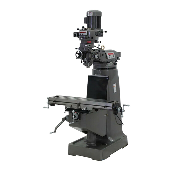
Operating Instructions and Parts Manual
Step Pulley Turret Mill
Model JTM-1, JTM-2
Model JTM-1 shown
JET
427 New Sanford Road
LaVergne, Tennessee 37086
Part No. M-690082
Ph.: 800-274-6848
Revision H 01/2016
www.jettools.com
Copyright © 2014 JET
Table of
Contents
Previous
Page
Next
Page
1
2
3
4
5
Advertisement
Table of Contents
Need help?
Do you have a question about the JTM-1 and is the answer not in the manual?
Ask a question
Questions and answers
Related Manuals for Jet JTM-1
Power Tool Jet JTM-1054R Specifications
Variable speed vertical milling machine (2 pages)
Power Tool Jet JTM-1050 Operating Instructions And Parts Manual
Variable speed turret mill (36 pages)
Power Tool JET JTS-8 Operating Instructions Manual
Jet jts-8 table saw (19 pages)
Power Tool JET JTS-315SP Operating Instructions Manual
Table saw (8 pages)
Power Tool Jet JTM-1254VS Operating Instructions And Parts Manual
Variable speed turret mill (52 pages)
Power Tool JET JTSS-1600 Operating Instructions Manual
(58 pages)
Power Tool JET JTM-2 Operating Instructions And Parts Manual
Step pulley turret mill (36 pages)
Power Tool Jet JTM-949EVS/230 Operating Instructions And Parts Manual
Electronic variable speed turret mill (48 pages)
Power Tool Jet JTM-1050VS2 Operating Instructions And Parts Manual
Variable speed turret mill (40 pages)
Power Tool Jet JJ-6CSDX Operating Instructions And Parts Manual
6-inch woodworking jointer (40 pages)
Power Tool Jet JJ-6HHDX Operating Instructions And Parts Manual
6-inch woodworking jointer (40 pages)
Power Tool Jet JDP-17MF Operating Instructions And Parts Manual
17” drill press (24 pages)
Power Tool Jet JDP-15M Operating Instructions Manual
(20 pages)
Power Tool Jet JWS-35X Series Operating Instructions And Parts Manual
Jet jws-35x shapers: user guide (49 pages)
Power Tool Jet JAT-820 Operations & Parts Manual
(13 pages)
Power Tool Jet JSSG-8-M Operating Instructions Manual
Slow speed wet sharpener (22 pages)
This manual is also suitable for:
Jtm-2
Table of Contents
Print
Rename the bookmark
Delete bookmark?
Delete from my manuals?
Login
Sign In
OR
Sign in with Facebook
Sign in with Google
Upload manual
Upload from disk
Upload from URL


Need help?
Do you have a question about the JTM-1 and is the answer not in the manual?
Questions and answers