Table of Contents
Advertisement
This .pdf document is bookmarked
Operating Instructions and Parts Manual
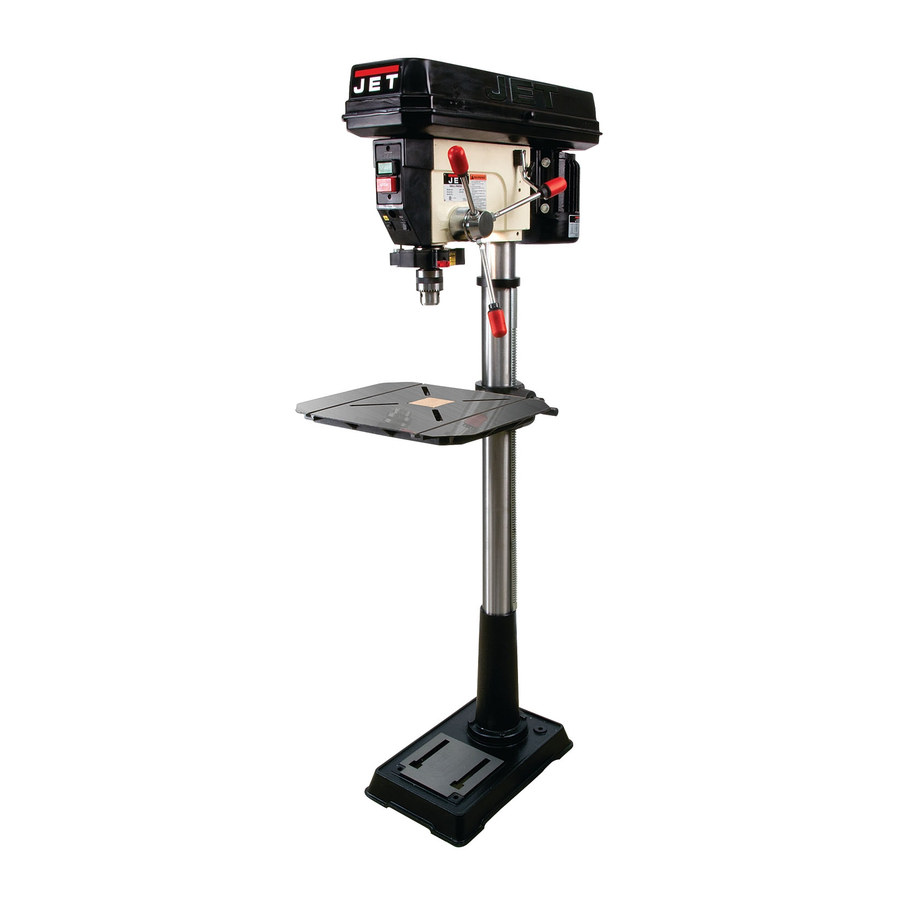
17" Floor Drill Press
Model: JDP-17DX
WALTER MEIER (Manufacturing) Inc.
427 New Sanford Road
LaVergne, Tennessee 37086
Part No. M-354173
Ph.: 800-274-6848
Revision C 04/2012
www.waltermeier.com
Copyright © 2012 Walter Meier (Manufacturing) Inc.
Advertisement
Table of Contents

Related Manuals for Jet JDP-17DX


Summary of Contents for Jet JDP-17DX
- Page 1 This .pdf document is bookmarked Operating Instructions and Parts Manual 17" Floor Drill Press Model: JDP-17DX WALTER MEIER (Manufacturing) Inc. 427 New Sanford Road LaVergne, Tennessee 37086 Part No. M-354173 Ph.: 800-274-6848 Revision C 04/2012 www.waltermeier.com Copyright © 2012 Walter Meier (Manufacturing) Inc.
-
Page 2: Warranty And Service
Walter Meier Authorized Service Centers can authorize warranty repair, assist you in obtaining parts, or perform routine maintenance and major repair on your JET® tools. For the name of an Authorized Service Center in your area call 1-800-274-6848. -
Page 3: Table Of Contents
Table of Contents Warranty and Service..........................2 Table of Contents ..........................3 Warnings............................4 Switch Padlock..........................5 Introduction ............................6 Unpacking ............................7 Contents of the Shipping Container ....................7 Assembly ............................8 Base and Column Assembly ......................8 Table and Rack ..........................8 Table Crank and Column Lock Handles ....................8 Mounting the Head ..........................9 Downfeed Handles ..........................9 Installing the Chuck and Arbor......................9... -
Page 4: Warnings
Warnings Read and understand the entire owners' manual before attempting assembly or operation. Read and understand the warnings posted on the machine and in this manual. Failure to comply with all of these warnings may cause serious injury. Replace the warning labels if they become obscured or removed. This drill press is designed and intended for use by properly trained and experienced personnel only. -
Page 5: Switch Padlock
Switch Padlock To safeguard your machine from unauthorized operation and to avoid accidental starting by young children, the use of a padlock is highly recommended. A padlock (stock no. 709012-A) is available from your local authorized JET distributor calling Walter Meier (Manufacturing) Inc., at 800-274-6848. -
Page 6: Introduction
Introduction This manual is provided by Walter Meier (Manufacturing) Inc., covering the safe operation and maintenance procedures for the JET JDP-17DX Drill Press. This manual contains instructions on installation, safety precautions, general operating procedures, maintenance instructions and parts breakdown. This machine has been designed and constructed to provide years of trouble free operation if used in accordance with instructions set forth in this manual. -
Page 7: Unpacking
1. Remove the contents from the shipping container. 2. Compare the contents of the shipping container with the list found above. Report any shortages or damage to your JET distributor. 3. Clean all rust protected surfaces with kerosene or a light solvent. Do not use lacquer thinner, paint thinner, or gasoline. -
Page 8: Assembly
Assembly Base and Column Assembly Referring to Figure 1: 1. Place the base (A) on a level floor. 2. Place the column assembly (B) on the base (A) and align the holes in the column support with the holes in the base. 3. -
Page 9: Mounting The Head
Mounting the Head 1. With the aid of a second person, carefully lift the head onto the column top (Figure 3). The head assembly is heavy! To avoid injury and/or damage to equipment, lift the head onto the column only with additional assistance! 2. -
Page 10: Electrical
adapter, which looks like the adapter shown in Electrical (B), may be used to connect this plug to a two- pole receptacle if a properly grounded outlet is Grounding Instructions not available. The temporary adapter should only be used until a properly grounded outlet In the event of a malfunction or breakdown, can be installed by a qualified electrician. -
Page 11: Adjustments
Adjustments Removing the Chuck and Arbor Referring to Figure 7: 1. Unplug machine from the power source. 2. Raise the table until it is about seven inches below the chuck. 3. Place a piece of scrap wood on the table, and lower quill using... -
Page 12: Return Spring Adjustment
Return Spring Adjustment Figure 9 The return spring is located behind the left 5. Rotate the coil spring cover (M) until the downfeed handle hub. It is adjusted at the notch on the cover engages with the tab (L) factory and should not need further adjustment. on the head casting. -
Page 13: Laser Adjustment
Laser Adjustment The Laser Assembly has been installed and preset at the factory. It should, however, be checked and adjustments made, if necessary, before operating the drill press. It should also be rechecked periodically, as constant machine use may cause it to become misaligned. -
Page 14: Laser Assembly Removal/Installation
Laser Assembly Removal/Installation The JDP-17DX drill press can be used as a mortiser when fitted with a mortiser adapter (not included). When used as a mortiser, the laser assembly must be removed as follows: Referring to Figure 14: 1. Unplug machine from the power source. -
Page 15: Operating Controls
Operating Controls Basic Operation Refer to Figure 15: Always use a back-up piece of scrap wood to cover the table. This protects both the Start Switch (A) – Press to start machine table and the drill bit. Stop Switch (B) – Press to stop machine Place material to be drilled in such a way as Light Switch (C) –... -
Page 16: Troubleshooting
Troubleshooting Trouble Probable Cause Remedy Drill press unplugged from wall or Check all plug connections. motor. Fuse blown or circuit breaker tripped. Replace fuse or reset circuit breaker. Drill press will not start. Cord damaged. Replace cord. Starting capacitor bad. Replace starting capacitor. -
Page 17: Parts
Parts Ordering Replacement Parts To order parts or reach our service department, call 1-800-274-6848 Monday through Friday (see our website for business hours, www.waltermeier.com). Having the Model Number and Serial Number of your machine available when you call will allow us to serve you quickly and accurately. Parts List Index No Part No Description... - Page 18 Parts List Index No Part No Description Size 41 .... 10661102 ....Seat ....................1 42 .... 13005601 ....Washer ....................1 43 .... 13005701 ....Nut ....................2 44 .... TS-1503081 ....Socket Head Cap Screw ........M6x35......2 45 .... TS-1540071 ....Hex Nut............M10 ......1 46 ....
- Page 19 Parts List Index No Part No Description Size 95 .... JDP17DX-095 ..Rubber Seal ..................1 96 .... JDP17DX-096 ..Pulley Cover Assembly ............... 1 97 .... JDP17DX-097 ..Chuck & Key ..................1 98 .... 561708....Drill Chuck ............5/8” ......1 99 .... CK-16 .....Drill Chuck Key ..........5/8" ......1 100 ..
- Page 20 154 ..JDP17DX-154 ..Light Label ..................1 155 ..JDP17DX-155 ..Laser Caution/Warning Label .............. 1 156 ..10916202 ....Warning Label ..................1 157 ..11316904 ....JET Label................... 1 158 ..JDP17DX-158 ..Speed Label ..................1 159 ..JDP17DX-159 ..Motor Label ..................1 160 ..
-
Page 21: Assembly Drawing
Assembly Drawing... -
Page 22: Wiring Diagram
Wiring Diagram... - Page 23 Notes...
- Page 24 WALTER MEIER (Manufacturing) Inc. 427 New Sanford Road LaVergne, Tennessee 37086 Phone: 800-274-6848 www.waltermeier.com...
Need help?
Do you have a question about the JDP-17DX and is the answer not in the manual?
Questions and answers