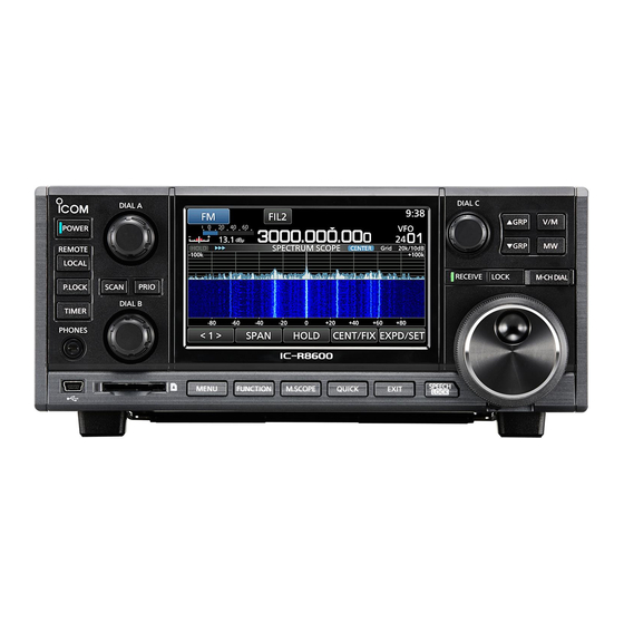
Icom IC-R8600 Reference Manual
Communications receiver, i/q output
Hide thumbs
Also See for IC-R8600:
- Instruction manual (96 pages) ,
- Service manual (84 pages) ,
- How-to manual (11 pages)
Table of Contents
Advertisement
Advertisement
Table of Contents

Summary of Contents for Icom IC-R8600
- Page 1 I/Q OUTPUT REFERENCE GUIDE COMMUNICATIONS RECEIVER iR8600...
-
Page 2: Table Of Contents
■ Control commands relative to I/Q port setting D Receive frequency ……………………………… 10 D Receive Band edge frequency ………………… 10 D I/Q Output setting …………………………………11 ■ Operations while the IC-R8600 is in the I/Q mode 13 D Operation limitations in the I/Q mode ………… 13... -
Page 3: I/Q Signal
D General description You can get I/Q signals from the [I/Q OUT] port on the IC-R8600 by connecting the IC-R8600 and a PC, with a USB cable. You can receive I/Q signals and control the IC-R8600, through the USB cable. -
Page 4: Communication Through The [I/Q Out] Port
The communications are done through WinUSB. To use WinUSB, you need to install the driver (USB I/Q Package for HDSDR) that can be downloaded from Icom web site. After the driver is installed, you can receive I/Q signals and control the IC-R8600 through the WinUSB, using an I/Q receive software (user supplied). -
Page 5: About The I/Q Signals
I/Q SIGNAL ■ About the I/Q signals D General description I/Q data is output from the [I/Q OUT] port on the IC-R8600. 1 endpoint is reserved to receive I/Q signals. Address Endpoint Number Direction Transfer Type (Hexadecimal) (Hexadecimal) I/Q data Bulk transfer IC-R8600 →... -
Page 6: I/Q Data Details
I/Q SIGNAL ■ I/Q data details D 24-bit long I/Q data Data format: The I/Q data is composed of 3 parts: “I” signals, “Q” signals and Synchronous signals. Each data length is: “I” = 24 bits (3 Bytes), “Q” =24 bits (3 Bytes), Synchronous data=48 bits (6 Bytes). (The byte order is in the little-endian format.) …... -
Page 7: D Remarks
I/Q SIGNAL ■ I/Q data details (Continued) D Remarks The I/Q data contains a DC component that is produced in the signal processing. The DC component appears as a constant frequency component positioned at the center frequency (0 Hz). A lower sampling frequency makes the DC component level greater. DC component An example of the DC component that is monitored on the HDSDR software. -
Page 8: Control Commands
LThere are 2 command types: Writing commands and Reading commands. Refer to the next topic for details about them. D Command format You can control the IC-R8600 using the CI-V commands. Every command is composed of a byte array in hexadecimal. Every command’s total length in bytes must be an even number. - Page 9 If the total length is an odd number, you need to add an extra “FF” at the end of the packet, to make the length an even number. In the same manner, the length of the acknowledgement data from the IC-R8600 is an even number.
-
Page 10: Usable Control Commands
I/Q SIGNAL ■ Usable control commands D Command description Some commands can both read and write data, while others can only read or write. Usable commands differ, according to the I/Q mode state (ON or OFF). When the When the Command command Data... -
Page 11: Control Commands Relative To I/Q Port Setting
L You can omit the upper digits entry. When omitted, the current frequency is applied. D Receive Band edge frequency Command: 1A 0F PC to IC-R8600 (Write data format) Specify the band edge to read by the edge number in a BCD code. Edge number: 0 1 to XX* L The upper number (*marked) will be the returned value of command “1A 0E.”... -
Page 12: D I/Q Output Setting
Only when the I/Q mode is set to “ON,” you can set the I/Q output to ON. When the sent command is valid and accepted by the IC-R8600, the acknowledgement “OK (FB)” will be returned. “NG (FA)” will be returned if invalid. - Page 13 I/Q SIGNAL ■ Control commands relative to I/Q port setting D I/Q Output setting (Continued) IC-R8600 to PC (Read data format): Reads the I/Q output settings. • When the I/Q signal output is OFF I/Q output setting 0 =OFF 0 (Fixed) •...
-
Page 14: Operations While The Ic-R8600 Is In The I/Q Mode
While the IC-R8600 is in the I/Q mode, [REMOTE] LED lights and the IC-R8600 is in the “Remote controlled mode,” thus you cannot operate the IC-R8600. To exit the I/Q mode, send the command that cancels the mode, or push the [LOCAL] key on the IC-R8600 front panel. Turning OFF the IC-R8600’s power also exits the I/Q mode. - Page 15 A7375-11EX © 2018 Icom Inc. 1-1-32 Kamiminami, Hirano-ku, Osaka 547-0003, Japan...


Need help?
Do you have a question about the IC-R8600 and is the answer not in the manual?
Questions and answers