Table of Contents
Advertisement
Quick Links
Download this manual
See also:
Manual
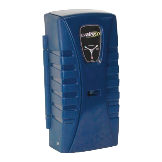
UV-AIRE
Model: UV-12C, 18C, 28C, 28, 12HP, 18HP, 28HP, 12HPC, 18HPC, 28HPC
UV-C light inhibits the growth and reproduction of germs and bacteria that circulate through a home's
heating and air conditioning system. The treatment is a safe, silent, and proven way to make your home a
healthier place to live.
SAFETY CONSIDERATIONS
WARNING: Never expose eyes or skin to UV-C light from any source.
• Looking directly at the UV-C light may cause permanent eye damage or blindness.
• Never operate the UV-Aire Air Purifying System out of the plenum.
• Designed for a closed duct system. Do not mount near a return air opening
• All duct openings in direct line of site of the UV light must be sealed with duct tape or equivalent
sealing methods.
WARNING: UV light will break down plastic materials not rated for UV exposure:
(Examples: wire insulation, flex duct, drain pans and humidifiers)
• The unit must be mounted at least 30" from the above stated type of materials.
• If it is necessary to mount the unit in direct line of sight of these types of materials, they must be
shielded with aluminum foil, aluminum foil tape, or sheet metal.
WARNING: DO NOT mount this unit outdoors.
• This product is designed for indoor installation only (i.e. attics, crawl spaces, basements, etc.).
This product is not sold as a medical device and is not for the purpose of diagnosis of any disease or condition nor for
use in the mitigation, treatment, or prevention of any disease or condition.
READ THESE INSTRUCTIONS CAREFULLY AND COMPLETELY BEFORE PROCEEDING WITH THE INSTALLATION.
This device MUST be installed by a qualified agency in accordance with the manufacturer's installation instructions. The definition of
a qualified agency is: any individual, firm, corporation or company which either in person or through a representative is engaged
in, and is responsible for, the installation and operation of HVAC appliances, who is experienced in such work, familiar with all the
precautions required, and has complied with all the requirements of the authority having jurisdiction.
Installed By:
AIR PURIFYING SYSTEM
®
*Exclusive 5 position lamp mounting feature!
Please retain these instructions after installation.
Phone:
www.fieldcontrols.com
ITEMS INCLUDED IN KIT:
1- UV-Aire power unit
4- Sheet metal mounting screws
1- Angled mounting bracket
1- Flat mounting bracket
1- Duct board mounting bracket
1- Ultra Violet Lamp
1- Instruction Sheet
1- Wing nut
Caution Labels
Gasket
Installation Date:
Advertisement
Table of Contents

Related Manuals for Field Controls UV-AIRE UV-12C


Summary of Contents for Field Controls UV-AIRE UV-12C
- Page 1 UV-AIRE ® Model: UV-12C, 18C, 28C, 28, 12HP, 18HP, 28HP, 12HPC, 18HPC, 28HPC UV-C light inhibits the growth and reproduction of germs and bacteria that circulate through a home’s heating and air conditioning system. The treatment is a safe, silent, and proven way to make your home a healthier place to live.
-
Page 2: Indication For Use
UV-28HPC 22" The UV-12C,18C, 28C,12HPC,18HPC, and 28HPC units are equipped with a circuit board to monitor the operation of the UV lamp; it indicates the operation of the lamp through an LED indicator light mounted on the cover of the unit. The circuit board indicates good operation of the lamp by a continuous GREEN color on the LED light. After 8,320 hours of lamp operation, the circuit board indicates the elapsed time of lamp operation... -
Page 3: Installation
INSTALLATION Locate a suitable location for the unit downstream from the 'A' coil in the supply plenum or in the return plenum; preferably downstream from the air filter. For optimum cleaning effect on the 'A' coil, mount the unit in the supply plenum as close as possible to the 'A' coil. (See Figure 1) Minimum Length or Width UV-12 = 12 inches UV-18 = 18 inches... - Page 4 Determine the type of duct you have. IF YOU HAVE FLEx DUCT For installations on duct systems with a metallic main duct and flex duct branches, follow the instructions in figure 2A below. IF YOU HAVE METAL DUCT: Apply supplied wet and stick mounting template to air duct in either a vertical or horizontal position as shown in Figure 2B. Drill ⁄...
- Page 5 IF YOU HAVE DUCT BOARD: Mount the supplied metal mounting plate onto the duct with duct tape in either a vertical or horizontal position. (See Figures 2B & 3) Bend tabs outward as shown in Figure 4. Using a knife or blade, cut out a rectangle opening in the duct using the mounting plate as a template. (See Figure 5) Remove the cut piece of duct. (See Figure 6) Bend both tabs down and through duct at first bend point. (See Figures 7 & 8)
- Page 6 Remove base unit and cover from box. Apply supplied Duct Seal Kit according to instructions included in kit. (See Figure 12) Determine whether to use flat or angled bracket. (Refer to Bulb Mounting Bracket Selection) Flat Bracket Installation i. Remove the two hex nuts and flat bracket from included bagged hardware. ii. Install the flat bracket and secure to the unit base with the hex nuts provided. (See Figure 13) Angled Bracket Installation NOTE: For angled bracket mounting, refer to specifications outlined by Charts A & B for mounting distances in the Angled Lamp Mounting Bracket Specifications.
- Page 7 Swing the swivel bracket over the end of lamp. Hand-tighten the wing nut on the stud. Be careful not to over tighten the wing nut. The porcelain at the lamp base may crack when over tightened. (See Figure 17) 10. Plug ballast plug into end of lamp. (See Figure 18) Snap cover onto the unit base. (See Figure 19) Plug the LED wire from the cover onto the board. (See Figure 20) 13.
- Page 8 INCORPORATING A THERMOSTAT (Be sure to follow any applicable state or local codes.) The UV Aire units supplied with a circuit board allow for the automatic operation of the UV lamp when the there is a call for heating or cooling by the thermostat. After the call for heat has been satisfied, the UV Aire unit will operate for 45 minutes then shut off.
- Page 9 SYSTEM CHECK OUT PROCEDURE Plug the UV Aire back into the power receptacle and leave the power switch in the OFF position. Unplug the Ballast connector from the lamp and switch the power switch to the ON position. The unit will start and operate for approximately 10 seconds. Then the LED will switch to a RED color and the alarm contact will close.
-
Page 10: Maintenance
ANGLED LAMP MOUNTING BRACKET SPECIFICATIONS Use the specifications below to determine allowable clearances for proper mounting of the UV-Aire unit on the duct. LAMP OFFSET DIMENSIONS Unit Min. Duct Size (inches) UV-12C 9 x 12 UV-18C 14 x 18 UV-28C 22 x 24... -
Page 11: Troubleshooting Guide
UV-28HPC 46365403 For replacement parts, contact your local heating service company. Any questions, please contact Field Controls at: • Phone: 252-522-3031 • Fax: 252-522-0214 • Email: sales@fieldcontrols.com WARNING: Never expose eyes or skin to UVC light from any source. Looking directly at the UVC light may cause permanent eye damage or blindness. -
Page 12: Limited Warranty
Field Controls Direct Vent Systems (FDVS), Field Oil Vent Kits (FOVP), and ComboVents (CV). Field Controls warrants that the products listed below shall be free from defects in material and workmanship under normal use for the limited period indicated, from the date of purchase by the consumer, subject to the provisions 1-8 below.
Need help?
Do you have a question about the UV-AIRE UV-12C and is the answer not in the manual?
Questions and answers