Qlogic 5800V Series Installation Manual
Stackable fibre channel switch
Hide thumbs
Also See for 5800V Series:
- Interface manual (422 pages) ,
- User manual (256 pages) ,
- Quick start manual (8 pages)

Related Manuals for Qlogic 5800V Series


Summary of Contents for Qlogic 5800V Series
-
Page 1: Installation Guide
Installation Guide Stackable Fibre Channel Switch 5800V Series Firmware Version 8.0 59265-02 B... -
Page 2: Document Revision History
QLogic Corporation reserves the right to change product specifications at any time without notice. Applications described in this document for any of these products are for illustrative purposes only. QLogic Corporation makes no representation nor warranty that such applications are suitable for the specified use without further testing or modification. -
Page 3: Table Of Contents
Table of Contents Preface Intended Audience ..........Related Materials . - Page 4 Installation Guide Stackable Fibre Channel Switch 5800V Series System Fault LED (Amber) ....... . . Maintenance Button.
- Page 5 Installation Guide Stackable Fibre Channel Switch 5800V Series Transparent Routing ........2-13 Switch Services .
- Page 6 Installation Guide Stackable Fibre Channel Switch 5800V Series Diagnostics/Troubleshooting Chassis Diagnostics ......... . . Input Power LED Is Not Lit .
- Page 7 QLogic 5802V Fibre Channel Switch ........
- Page 8 Installation Guide Stackable Fibre Channel Switch 5800V Series List of Tables Table Page Fibre Channel Port Types ..........Serial Port Pin Identification .
-
Page 9: Preface
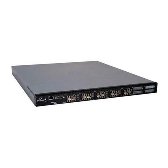
This guide describes the features and installation of the QLogic 5800V Series Stackable Fibre Channel switch, firmware version 8.0. The QLogic 5800V Series switch is a 24-port, 8Gbps Fibre Channel switch. The model 5802V switch has dual, replaceable power supplies; the model 5800V switch has a single, non-replaceable power supply. -
Page 10: Related Materials
Related Materials The following materials are referenced in the text or provide additional information. QLogic 5800V Series Fibre Channel Switch Command Line Interface Guide QLogic Fibre Channel Switch CLI Quick Reference Guide QLogic 5800V Series Enterprise Fabric Suite User’s Guide ... -
Page 11: Safety Notices
Preface Safety Notices Safety Notices A Warning notice indicates the presence of a hazard that has the potential of causing personal injury. The following pages contain warnings: 3-4, A Caution notice indicates the presence of a hazard that has the potential of causing damage to the equipment. -
Page 12: Communications Statements
Preface Communications Statements Communications Statements The following statements apply to this product. The statements for other products intended for use with this product appear in their accompanying manuals. Federal Communications Commission (FCC) Class A Statement This equipment has been tested and found to comply with the limits for a Class A digital device, pursuant to Part 15 of the FCC Rules. -
Page 13: Ce Statement
Preface Communications Statements CE Statement The CE symbol on the equipment indicates that this system complies with the EMC (Electromagnetic Compatibility) directive of the European Community (2004/108/EC) and to the Low Voltage (Safety) Directive (2006/95/EC). Such marking indicates that this system meets or exceeds the following technical standards: ... -
Page 14: Laser Safety Information
The assemblies used in the switch chassis are ESD sensitive. Observe ESD handling procedures when handling any assembly used in the switch chassis. Accessible Parts The Field Replaceable Units (FRUs) for the QLogic 5800V Series switch are the following: ... -
Page 15: Pièces Accessibles
Interfaces aux media d’interconnexion appelés SFP transceivers Interfaces aux media d’interconnexion appelés XPAK transceivers Zugängliche Teile Nur die folgenden Teile im QLogic 5800V Series Fibre Channel Switch können kundenseitig ersetzt werden: Netzteile Schnittstellen für die Zwischenverbindungsträger, SFP transceivers genannt. -
Page 16: General Public License
General Public License General Public License QLogic Fibre Channel switches are powered by the Linux operating system. A machine-readable copy of the Linux source code is available upon written request to the following address. A nominal fee will be charged for reproduction, shipping, and handling costs in accordance with the General Public License. -
Page 17: Terms And Conditions For Copying, Distribution And Modification
Preface General Public License We protect your rights with two steps: (1) copyright the software, and (2) offer you this license which gives you legal permission to copy, distribute and/or modify the software. Also, for each author's protection and ours, we want to make certain that everyone understands that there is no warranty for this free software. - Page 18 Preface General Public License You may modify your copy or copies of the Program or any portion of it, thus forming a work based on the Program, and copy and distribute such modifications or work under the terms of Section 1 above, provided that you also meet all of these conditions: You must cause the modified files to carry prominent notices stating that you changed the files and the date of any change.
- Page 19 Preface General Public License and 2 above on a medium customarily used for software interchange; Accompany it with a written offer, valid for at least three years, to give any third party, for a charge no more than your cost of physically performing source distribution, a complete machine-readable copy of the corresponding source code, to be distributed under the terms of Sections 1 and 2 above on a medium customarily used for software...
- Page 20 Preface General Public License Each time you redistribute the Program (or any work based on the Program), the recipient automatically receives a license from the original licensor to copy, distribute or modify the Program subject to these terms and conditions. You may not impose any further restrictions on the recipients' exercise of the rights granted herein.
- Page 21 Preface General Public License Each version is given a distinguishing version number. If the Program specifies a version number of this License which applies to it and "any later version", you have the option of following the terms and conditions either of that version or of any later version published by the Free Software Foundation.
- Page 22 Preface General Public License To do so, attach the following notices to the program. It is safest to attach them to the start of each source file to most effectively convey the exclusion of warranty; and each file should have at least the "copyright" line and a pointer to where the full notice is found.
-
Page 23: Qfsapp Program License
Preface qfsApp Program License Yoyodyne, Inc., hereby disclaims all copyright interest in the program `Gnomovision' (which makes passes at compilers) written by James Hacker. signature of Ty Coon, 1 April 1989 Ty Coon, President of Vice This General Public License does not permit incorporating your program into proprietary programs. -
Page 24: Technical Support
QLogic offers training for technical professionals for all storage networking, converged networking, and High Performance Computing (HPC) networking products. From the main QLogic Web page at www.qlogic.com, click the Support tab at the top, and then click the Training and Certification on the left. The QLogic Global Training Portal offers online courses, certification exams, and scheduling of in-person training. -
Page 25: Knowledge Base
Technical Support Knowledge Base The QLogic knowledge base is an extensive collection of QLogic product information that you can search for specific solutions. We are constantly adding to the collection of information in our knowledge base to provide answers to your most urgent questions. - Page 26 Preface Technical Support xxvi 59265-02 B...
-
Page 27: General Description
Channel switch with both Ethernet and serial management interfaces. The model 5802V has dual, replaceable power supplies; the model 5800V switch has a single, non-replaceable power supply. This section describes the features and capabilities of the QLogic 5800V Series switch including the following: ... -
Page 28: Chassis Controls And Leds
Refer to the QLogic 5800V Series QuickTools Switch Management User’s Guide for information about QuickTools. Refer to the QLogic 5800V Series Enterprise Fabric Suite User’s Guide for information about using the Enterprise Fabric Suite application. The Enterprise Fabric Suite CD comes with a 30-day trial license. -
Page 29: Heartbeat Led (Green)
1–General Description Chassis Controls and LEDs Heartbeat LED (Green) The Heartbeat LED indicates the status of the internal switch processor and the results of the power-on self test (POST). Following a normal power-up, the Heartbeat LED blinks approximately once per second to indicate that the switch passed the POST and that the internal switch processor is running. -
Page 30: Fibre Channel Ports
Setting an SFP port to 1Gbps that has an 8Gbps SFP transceiver will bring down the port. The QLogic 5800V Series switch can be a 12-, 16-, 20-, or 24-port switch. For example, the base 12-port switch enables the four XPAK ports and SFP ports 0–7. -
Page 31: Port Leds
Transceivers The QLogic 5800V Series switch supports SFP optical transceivers for the SFP ports, and XPAK optical transceivers or XPAK stacking cables for the XPAK ports. A transceiver converts electrical signals to and from optical laser signals to transmit and receive data. -
Page 32: Port Types
“Install the Transceivers” on page 3-5. Port Types QLogic 5800V Series switches support generic ports (G_Port, GL_Port), fabric ports (F_Port, FL_Port), and expansion ports (E_Port). Switches come from the factory with all SFP ports configured as GL_Ports. The XPAK ports come from the factory configured as G_Ports. -
Page 33: Ethernet Port
1–General Description Ethernet Port Ethernet Port The Ethernet port is an RJ-45 connector that provides a connection to a management workstation through a 10/100 Base-T Ethernet cable as shown in ® ® ® Figure 1-5. A management workstation can be a Windows , Solaris , or a Linux workstation that is used to configure and manage the switch fabric. -
Page 34: Serial Port
1–General Description Serial Port Serial Port The QLogic 5800V Series switch is equipped with an RS-232 serial port for maintenance purposes, as shown in Figure 1-6. You can manage the switch through the serial port using the CLI. RS-232 Connector... -
Page 35: Power Supplies And Fans
1–General Description Power Supplies and Fans Power Supplies and Fans The model 5800V switch is equipped with a single, non-replaceable power supply. The model 5802V switch is equipped with dual, replaceable power supplies. Model 5800V The model 5800V switch has a single power supply that converts 100–240 VAC to DC voltages for the various switch circuits. -
Page 36: Switch Management
User account configuration Switch and fabric events Operational and environmental statistics Global device nicknames Online help For more information about QuickTools, refer to the QLogic 5800V Series QuickTools Switch Management User’s Guide. 1-10 59265-02 B... -
Page 37: Enterprise Fabric Suite
Application Programming Interface The API enables an application provider to build a management application for QLogic switches. The library is implemented in ANSI standard C, relying only on standard POSIX run-time libraries. Contact your distributor or authorized reseller for information about the API. -
Page 38: Simple Network Management Protocol
1–General Description Switch Management Simple Network Management Protocol SNMP provides monitoring and trap functions for the fabric. QLogic firmware supports SNMP versions 1, 2, and 3, the Fibre Alliance Management Information Base (FA-MIB) version 4.0, and the Fabric Element Management Information Base (FE-MIB) RFC 2837. -
Page 39: Planning
Planning Consider the following when planning a fabric: Devices Device Access Performance Feature Licensing Multiple Chassis Fabrics Switch Services Internet Protocol Support Security Fabric Management Devices When planning a fabric, consider the number of devices and the anticipated demand. -
Page 40: Device Access
2–Planning Device Access Device Access Consider device access needs within the fabric. Access is controlled through the use of zoning. Some zoning strategies include the following: Separate devices by operating system. Separate devices that have no need to communicate with other devices in the fabric or that have classified data. -
Page 41: Performance
Performance Performance The QLogic 5800V Series switch supports class 2 and class 3 Fibre Channel service at transmission rates of 1, 2, 4, 8,10, or 20Gbps with a maximum frame size of 2148 bytes. Each Fibre Channel port adapts its transmission speed to match that of the device to which it is connected prior to login, when the connected device powers up. -
Page 42: Bandwidth
2–Planning Performance Extending credits requires a minimum cable length that is dependent on transmission speed. Extending credits over short cables can cause excessive port resets. Table 2-3 lists the possible distances and minimum cable lengths for a port with 30 credits. Table 2-3. -
Page 43: Latency
2–Planning Feature Licensing Latency Latency is a measure of how fast a frame travels through a switch from one port to another. The factors that affect latency include transmission rate and the source and destination port relationship as shown in Table 2-4. -
Page 44: Multiple Chassis Fabrics
Transparent routing to a legacy fabric is also possible using TR_Ports. You can connect up to six QLogic 5800V Series switches through the XPAK ports, thus preserving the SFP ports for devices. This is called stacking. QLogic 5800V Series switches divide the XPAK port buffer to balance traffic across the connection. -
Page 45: Domain Id, Principal Priority, And Domain Id Lock
1, the domain ID lock set to False, and the principal priority set to 254. For information about changing the default domain ID, domain ID lock, and principal priority parameters, refer to the Set Config Switch command in the QLogic 5800V Series Fibre Channel Switch Command Line Interface Guide. -
Page 46: Stacking
Multiple Chassis Fabrics Stacking You can connect up to six QLogic 5800V Series switches through the XPAK ports, thus preserving the SFP ports for devices. This is called stacking. The following 2-, 3-, 4-, 5-, and 6-switch stacking configurations are recommended for best performance and redundancy. -
Page 47: Four-Switch Stack
2–Planning Multiple Chassis Fabrics Figure 2-3 shows a four-switch stack of model 5800V Series switches using three 3-inch and three 9-inch XPAK switch stacking cables. Eighty SFP ports are available for devices. Figure 2-3. Four-Switch Stack Figure 2-4 shows a five-switch stack of model 5800V Series switches using four 3-inch and six 9-inch XPAK switch stacking cables. -
Page 48: Common Topologies
Although QLogic recommends using the XPAK stacking ports to achieve the highest cabling efficiency and bandwidth, you can also create multiple switch configurations using the SFP ports. The QLogic 5800V Series switch supports the following topologies using the SFP ports: ... -
Page 49: Cascade Topology
The loop also provides failover if a switch fails. Using 24-port QLogic 5800V Series switches, the cascade fabric shown in Figure 2-6 has the following characteristics: ... -
Page 50: Mesh Topology
Multiple Chassis Fabrics Mesh Topology A mesh topology describes a fabric in which each chassis has at least one port directly connected to each other chassis in the fabric. Using 24-port QLogic 5800V Series switches, the mesh fabric shown in Figure 2-7... -
Page 51: Multistage Topology
Multiple Chassis Fabrics MultiStage Topology A Multistage topology describes a fabric in which two or more edge switches connect to one or more core switches. Using 24-port QLogic 5800V Series switches, the Multistage fabric shown in Figure 2-8 has the following characteristics: ... - Page 52 Guide, and the QLogic 5800V Series Fibre Channel Switch Command Line Interface Guide. You can connect multiple QLogic 5800V Series Fibre Channel Switches to one or more remote fabrics using multiple TR_Ports. Local and remote devices are identified by their respective port worldwide names. Consider the following mapping rules: ...
- Page 53 WWNs of the remote devices to be mapped and the WWNs of the QLogic 5800V Series Fibre Channel Switch TR ports are zoned together. For more information, see the Cisco documentation for specific information to configure zoning.
-
Page 54: Switch Services
Brocade or Cisco switches, will make the necessary zoning changes to the remote fabric. See the QLogic 5800V Series QuickTools Switch Management User’s Guide or QLogic 5800V Series Enterprise Fabric Suite User’s Guide for important details on creating and using this list... - Page 55 2–Planning Switch Services Secure Socket Layer (SSL): Provides secure connections for Enterprise Fabric Suite, the QuickTools Web applet, the API, and SMI-S. This service must be enabled to authenticate users through a remote authentication dial in-user service (RADIUS) server when using Enterprise Fabric Suite. To enable SSL connections, you must first synchronize the date and time on the switch and workstation.
-
Page 56: Internet Protocol Support
2–Planning Internet Protocol Support Internet Protocol Support The switch supports IP version 4 (IPV4), IP version 6 (IPV6), and DNS host names. IPV4 and IPV6 are enabled by default. Consider your IP version requirements and the availability of a DNS server. Security Security is available at the following levels: ... -
Page 57: Ip Security
32 are refused access to the port. Consider what ports to secure and the set of switches and devices that are permitted to log in to those ports. For information about port binding, refer to the QLogic 5800V Series Fibre Channel Switch Command Line Interface Guide. -
Page 58: Connection Security
If the certificate becomes invalid, create a new certificate using the Create Certificate CLI command. For information about the CLI commands, refer to the QLogic 5800V Series Fibre Channel Switch Command Line Interface Guide. Consider your connection security requirements: for the command line interface (SSH), management applications such as Enterprise Fabric Suite (SSL), or both. -
Page 59: Security Example: Switches And Adapters With Authentication
2–Planning Security In addition to authorization, you can configure the switch to require authentication to validate the identity of the connecting switch, device, or host. Authentication can be performed locally using the switch’s security database, or remotely using a RADIUS server such as Microsoft RADIUS. With a RADIUS server, the security database for the entire fabric resides on the server. - Page 60 2–Planning Security Security Example: Switches and Adapters with Authentication Consider the fabric shown in Figure 2-9. In this fabric, Switch_1, Adapter_1, and Switch_2 support authentication, while the JBOD and Adapter_2 do not. The objective is to secure F_Ports and E_Ports in the fabric. Device: Adapter_2 WWN: 10:00:00:c0:dd:07:c3:4f Device: Adapter_1...
- Page 61 2–Planning Security To secure F_Ports and E_Ports in the fabric, configure security on the devices that support security: Switch_1, Switch_2, and Adapter_1: Create a security set (Security_Set_1) on Switch_1. Create a port group (Group_Port_1) in Security_Set_1 with Switch_1, Adapter_1, and JBOD as members, as shown in the following table: Switch_1 Node WWN: 10:00:00:c0:dd:07:e3:4c Authentication: CHAP...
- Page 62 2–Planning Security Create an ISL group (Group_ISL_1) in Security_Set_1 with Switch_1, Switch_2, Adapter_1, and JBOD as members, as shown in the following table: Switch_1 Node WWN: 10:00:00:c0:dd:07:e3:4c Authentication: CHAP Primary Hash: MD5 Primary Secret: 0123456789abcdef Binding: None Switch_2 Node WWN: 10:00:00:c0:dd:07:e3:4e Authentication: CHAP Primary Hash: MD5 Primary Secret: abcdefabcdef012...
-
Page 63: Security Example: Radius Server
2–Planning Security Security Example: RADIUS Server Consider the fabric shown in Figure 2-10. This fabric is similar to the one shown in Figure 2-9 with the addition of Radius_1 acting as a RADIUS server. Authorization and authentication are passed from the switch to Radius_1 in the following cases: ... - Page 64 2–Planning Security To secure F_Ports and E_Ports, and pass authorization and authentication to a RADIUS server: Configure the Radius_1 host as a RADIUS server on Switch_1 and Switch_2 to authenticate device logins, as shown in the following table: Device Authentication RadiusLocal—Authenticate devices using the Order RADIUS server security database first.
- Page 65 2–Planning Security Observe the following rules: Switch_1 and all devices and switches connected to Switch_1 must be included in the group even if the switch or device does not support authentication. Otherwise, the Switch_1 port will become isolated from the fabric. ...
- Page 66 2–Planning Security Create a security set (Security_Set_2) on Switch_2. Create an ISL group (Group_ISL_2) in Security_Set_2 with Switch_1 and Switch_2 as members, as shown in the following: Switch_2 Node WWN: 10:00:00:c0:dd:07:e3:4e Authentication: CHAP Primary Hash: MD5 Primary Secret: abcdefabcdef0123 Binding: None Switch_1 Node WWN: 10:00:00:c0:dd:07:e3:4c Authentication: CHAP...
-
Page 67: Security Example: Management Server
2–Planning Security Security Example: Host Authentication Consider the fabric shown in Figure 2-11. In this fabric, only Switch_2 and Adapter_2/APP_2 support security, where APP_2 is a host application. The objective is to secure the management server on Switch_2 from unauthorized access by an adapter or an associated host application. - Page 68 2–Planning Security To secure the management server on Switch_2 from unauthorized access by an adapter or an associated host application: Create a security set (Security_Set_2) on Switch_2. Create a management server group (Group_1) in Security_Set_2 with Switch_2 and Adapter_2 or APP_2 as its member. You must specify adapters by node WWN.
-
Page 69: Fabric Management
2–Planning Fabric Management Fabric Management The Enterprise Fabric Suite application runs on a management workstation and provides for the configuration, control, and maintenance of multiple fabrics. Supported platforms include Windows, Solaris, Linux, and Mac OS X. Enterprise Fabric Suite comes with a 30-day trial license—a permanent license is available for purchase from your authorized reseller. - Page 70 2–Planning Fabric Management 2-32 59265-02 B...
-
Page 71: Installation
Installing Firmware Adding a Switch to an Existing Fabric Installing Feature License Keys Site Requirements Consider the following items when installing a QLogic 5800V Series switch: Fabric Management Workstation Switch Power Requirements Environmental Conditions... -
Page 72: Fabric Management Workstation
3–Installation Site Requirements Fabric Management Workstation The requirements for fabric management workstations are described in Table 3-1. Table 3-1. Management Workstation Requirements Component Requirement Windows 2003 Operating System Windows XP, SP1 and SP2 Solaris 9, 10, and 10 x86 ... -
Page 73: Installing A Switch
3–Installation Installing a Switch Installing a Switch Unpack the switch and accessories. The QLogic 5800V Series product is shipped with the components shown in Figure 3-1: QLogic 5800V Series Fibre Channel switch (1) with firmware installed Power cord (1)—model 5800V ... -
Page 74: Mount The Switch
“Dimensions” on page A-5. Adhesive rubber feet are provided for surface mounts. Without the rubber feet, the switch occupies 1U of space in an EIA rack. Rack mounting requires a QLogic rail kit (part number SB-RACKKIT). WARNING!! Mount switches in the rack so that the weight is distributed evenly. An unevenly loaded rack can become unstable, possibly resulting in equipment damage or personal injury. -
Page 75: Install The Transceivers
3–Installation Installing a Switch CAUTION! If the switch is mounted in a closed or multi-rack assembly, the operating temperature of the rack environment may be greater than the ambient temperature. Be sure to install the chassis in an environment that is compatible with the maximum rated ambient temperature. -
Page 76: Removing Xpak Port Covers
3–Installation Installing a Switch If you are using the XPAK ports, remove the port covers, as shown in Figure 3-2. Figure 3-2. Removing XPAK Port Covers To install XPAK switch stacking cables, position the cable connectors with the circuit board toward the mid-line of the respective switch faceplates, as shown in Figure 3-3. -
Page 77: Configure The Workstation
3–Installation Installing a Switch Configure the Workstation If you plan to use the CLI to configure and manage the switch, you must configure the workstation. To configure the workstation, set the workstation IP address for Ethernet connections, or configure the workstation serial port. If you plan to use QuickTools or Enterprise Fabric Suite to manage the switch, the Configuration Wizard manages the workstation IP address for you—proceed to “Connect the... -
Page 78: Configuring The Workstation Serial Port
3–Installation Installing a Switch Configuring the Workstation Serial Port To configure the workstation serial port: Connect a null modem F/F DB9 cable from a COM port on the management workstation to the RS-232 serial port on the switch. Configure the workstation serial port according to your platform: ... -
Page 79: Connect The Switch To Ac Power
3–Installation Installing a Switch Connect the Switch to AC Power WARNING!! This product is supplied with a three-wire power cable and plug for the user’s safety (Table A-1). Use this power cable in conjunction with a grounded outlet to avoid electrical shock. An electrical outlet that is not correctly wired could place hazardous voltage on metal parts of the switch chassis. - Page 80 Table A-1. To power up a QLogic 5800V Series switch: For a model 5800V switch, connect the power cord to the AC power receptacle on the front of the switch chassis and to a grounded AC outlet.
-
Page 81: Connect The Workstation To The Switch
3–Installation Installing a Switch The Heartbeat LED indicates the results of the POST. The POST analyzes the condition of firmware, memories, data-paths, and switch logic circuitry. If the Heartbeat LED blinks steadily (about once per second), the POST was successful, and you can continue with the installation process. -
Page 82: Configure The Switch
Suite. Enterprise Fabric Suite is an optional, full fabric graphical user interface that comes with a 30-day trial license. For information about installing Enterprise Fabric Suite, refer to the QLogic 5800V Series Enterprise Fabric Suite User’s Guide. QuickTools Switch Configuration To log in and configure the switch using QuickTools: Open an Internet browser, and then type the default IP address 10.0.0.1 to... -
Page 83: Cable Devices To The Switch
For example: Switch (admin) #> config edit Switch (admin-config) #> set config switch For more information about the CLI commands, refer to the QLogic 5800V Series Fibre Channel Switch Command Line Interface Guide. Cable Devices to the Switch Connect cables to the SFP transceivers and their corresponding devices, and then power up the devices. -
Page 84: Installing Firmware
CLI, QuickTools, or Enterprise Fabric Suite. This guide describes how to install firmware using QuickTools and the CLI. For information about installing firmware using Enterprise Fabric Suite, refer to the QLogic 5800V Series Enterprise Fabric Suite User’s Guide. Using QuickTools to Install Firmware ... -
Page 85: Using Quicktools To Install Firmware
Hotreset command to perform a non-disruptive activation. Refer to “Custom Firmware Installation” on page 3-17. For more information about CLI commands, refer to the QLogic 5800V Series Fibre Channel Switch Command Line Interface Guide. One-Step Firmware Installation The Firmware Install and Image Install commands download the firmware image file from an FTP or TFTP server to the switch, unpack the image file, and perform a disruptive activation in one step. - Page 86 To install firmware using the CLI when an FTP server is present on the management workstation, use the Firmware Install command. For information about the CLI commands, refer to the QLogic 5800V Series Fibre Channel Switch Command Line Interface Guide.
-
Page 87: Custom Firmware Installation
3–Installation Installing Firmware Type the password for your account name (FTP only). For example: 331 Password required for johndoe. Password:****** 230 User johndoe logged in. The firmware will now be downloaded from the remote host to the switch, installed, and activated. Custom Firmware Installation A custom firmware installation downloads the firmware image file from an FTP or TFTP server to the switch, unpacks the image file, and resets the switch in... -
Page 88: Adding A Switch To An Existing Fabric
3–Installation Adding a Switch to an Existing Fabric Wait for following message to appear, indicating that the firmware image is unpacked. image unpack command result: Passed When prompted to reset the switch to activate the firmware, type the Hotreset command to attempt a non-disruptive activation. For example: Switch (admin) $>hotreset Adding a Switch to an Existing Fabric If there are no special conditions to be configured for the new switch, plug in the... -
Page 89: Installing Feature License Keys
Click Add to upgrade the switch. Allow a minute or two for the upgrade to complete. To upgrade a switch using the command line interface, refer to the Feature command in the QLogic 5800V Series Fibre Channel Switch Command Line Interface Guide. 59265-02 B... - Page 90 3–Installation Installing Feature License Keys 3-20 59265-02 B...
-
Page 91: Diagnostics/Troubleshooting
Diagnostics/Troubleshooting Diagnostic information about the switch is available through the chassis LEDs and the port LEDs. Diagnostic information is also available through the CLI, QuickTools, and Enterprise Fabric Suite event logs and error displays. This section describes the following types of diagnostics: ... -
Page 92: Input Power Led Is Not Lit
4–Diagnostics/Troubleshooting Chassis Diagnostics Input Power LED Is Not Lit The Input Power LED lights up to indicate that the switch logic circuitry is receiving the correct voltages. If the Input Power LED is not lit, do the following: Inspect the power cords and connectors. Is the cord unplugged? Is the cord or connector damaged? ... -
Page 93: Power-On Self Test Diagnostics
4–Diagnostics/Troubleshooting Power-On Self Test Diagnostics Power-On Self Test Diagnostics The POST diagnostic program performs the following tests: Checksum tests on the boot firmware in PROM and the switch firmware in flash memory Internal data loopback test on all ports ... -
Page 94: Internal Firmware Failure Blink Pattern
4–Diagnostics/Troubleshooting Power-On Self Test Diagnostics Internal Firmware Failure Blink Pattern An internal firmware failure blink pattern is two blinks followed by a two-second pause. The two-blink error pattern indicates that the firmware has failed; the switch must be reset. Momentarily press and release the Maintenance button to reset the switch. -
Page 95: Configuration File System Error Blink Pattern
4–Diagnostics/Troubleshooting Power-On Self Test Diagnostics Configuration File System Error Blink Pattern A configuration file system error blink pattern is four blinks followed by a two-second pause. The four-blink error pattern indicates that a configuration file system error has occurred, and that the configuration file must be restored. Two seconds Figure 4-4. -
Page 96: Over-Temperature Blink Pattern
4–Diagnostics/Troubleshooting Power-On Self Test Diagnostics Over-Temperature Blink Pattern An over-temperature blink pattern is five blinks followed by a two-second pause. The five-blink error pattern indicates that the air temperature inside the switch has exceeded the failure temperature threshold. Two seconds Figure 4-5. -
Page 97: Logged-In Led Indications
4–Diagnostics/Troubleshooting Power-On Self Test Diagnostics Logged-In LED Indications Port diagnostics are indicated by the Logged-In LED for SFP and XPAK ports as shown in Figure 4-6. XPAK Port SFP Port Logged-In LED Logged-In LED Figure 4-6. Logged-In LED The Logged-In LED has three indications: ... -
Page 98: E_Port Isolation
4–Diagnostics/Troubleshooting Power-On Self Test Diagnostics E_Port Isolation A Logged-In LED error indication is often the result of E_Port isolation. E_Port isolation can be caused by the following: Security failure A port configured as FL_Port is connected to another switch ... - Page 99 Is the port connected to a switch that supports connection to a TR_Port of an QLogic 5800V Series Fibre Channel Switch? Yes—Configure the port as a TR_Port and map the local and remote fabric devices.
-
Page 100: Excessive Port Errors
Loss-of-signal errors Port threshold alarm monitoring is disabled by default. For information about managing port threshold alarms, refer to the QLogic 5800V Series Fibre Channel Switch Command Line Interface Guide. If the count for any of these errors exceeds the rising trigger for three consecutive sample windows, the switch generates an alarm, disables the affected port, and changes the port operational state to down. -
Page 101: Transceiver Diagnostics
Transceiver Diagnostics Reset the port, and then perform an external port loopback test to validate the port and the SFP. For information about testing ports, refer to the QLogic 5800V Series Fibre Channel Switch Command Line Interface Guide or the QLogic 5800V Series QuickTools Switch Management User’s Guide. -
Page 102: Power Supply Diagnostics
4–Diagnostics/Troubleshooting Power Supply Diagnostics Power Supply Diagnostics A power supply has a Fault LED (Amber) and a Status LED (Green), as shown in Figure 4-7. Model 5802V power supplies are replaceable. Under normal operating conditions, the Power Supply Status LED is lit, and the Power Supply Fault LED is not lit. -
Page 103: Recovering A Switch Using Maintenance Mode
4–Diagnostics/Troubleshooting Recovering a Switch Using Maintenance Mode Recovering a Switch Using Maintenance Mode A switch can become inoperable or unmanageable for the following reasons: Corrupt firmware Lost IP address Corrupt switch configuration Forgotten password In these specific cases, you can recover the switch using maintenance mode. Maintenance mode temporarily returns the switch IP address to 10.0.0.1, and provides access to the following menu options: ... -
Page 104: Exiting The Maintenance Menu (Option 0)
4–Diagnostics/Troubleshooting Recovering a Switch Using Maintenance Mode The Maintenance menu lists several recovery options. To select a switch recovery option, type the corresponding number, and then press ENTER. Exit Image Unpack Reset Network Config Reset User Accounts to Default Copy Log Files Remove Switch Config Remake Filesystem Reset Switch... -
Page 105: Resetting The Network Configuration In Maintenance Mode (Option 2)
You can use FTP to download this file to the management workstation; however, you must download the logfile before resetting the switch. For information about downloading files from the switch, refer to the QLogic 5800V Series Fibre Channel Switch Command Line Interface Guide. -
Page 106: Remaking The File System In Maintenance Mode (Option 6)
Filesystem option resets the switch to the factory default values, including user accounts and zoning. For information about the factory default values, refer to the Reset command in the QLogic 5800V Series Fibre Channel Switch Command Line Interface Guide. CAUTION! -
Page 107: Removal/Replacement
Removal/Replacement This section describes the removal and replacement procedures for the following FRUs: SFP and XPAK transceivers Power supplies for model 5802V switches Transceiver Removal and Replacement The SFP and XPAK transceivers can be removed and replaced while the switch is operating without damaging the switch or the transceiver. -
Page 108: Power Supply Removal And Replacement
5–Removal/Replacement Power Supply Removal and Replacement Power Supply Removal and Replacement Model 5802V power supplies are hot-pluggable: you can remove or install one of the power supplies while the switch is operating without disrupting service. The power supplies are also interchangeable; that is, the left and right power supplies are the same unit. -
Page 109: Power Supply Installation
5–Removal/Replacement Power Supply Removal and Replacement To install a power supply: Confirm that the Heartbeat LED is blinking once per second (normal operation), so that the switch can correctly report the power supply status. Confirm that the new power supply is compatible with the switch air flow direction. - Page 110 5–Removal/Replacement Power Supply Removal and Replacement 59265-02 B...
-
Page 111: Specifications
Specifications This appendix contains the specifications for the QLogic 5800V Series Fibre Channel switch. To locate all connections, switches, controls, and components, refer to Section Fabric Specifications Maintainability Fabric Management Dimensions Electrical Power Cord Specifications ... - Page 112 A–Specifications Fabric Specifications Fabric Specifications Fibre Channel Protocols ....FC-AL Rev 4.6 FC-AL-2 Rev 7.0 FC-DA FC-FLA FC-FS-2 FC-GS-5 FC-FG FC-LS FC-MI-2 FC-PH Rev. 4.3 FC-PH-2 FC-PH-3 FC-PI-3 FC-SP FC-Tape FC-VI FC-SW-4 Fibre Channel Element MIB RFC 2837 Fibre Alliance MIB Version 4.0 Fibre Channel Classes of Service ..
- Page 113 A–Specifications Fabric Specifications Scalability........Maximum 239 switches, depending on configuration Maximum User Ports ...... > 475,000 ports depending on configuration Buffer Credits........16 buffer credits per port, ASIC embedded memory Media Type Ports 0–19 ........SFP optical transceiver Ports 20–23 ........XPAK switch stacking cables Fabric Port Speed Ports 0–19 ........
-
Page 114: Maintainability
A–Specifications Maintainability Maintainability Diagnostics ........Power-on self test (POST) analyzes all functional components except SFP transceivers. Port tests include online, internal, and external tests. User Interface ......... LED indicators Field Replaceable Units....Power supplies (model 5802V only) Fabric Management Management Methods ....Enterprise Fabric Suite graphical user interface QuickTools Web applet Command Line Interface... -
Page 115: Dimensions
(SKU: CPK-9000-US). This power cord is approved for North America (USA, Canada, Puerto Rico), Mexico, Central America, South America, Korea, Taiwan, Philippines, and Thailand. A similar power cord with a locking plug is also available (SKU: CPK-9000-USL). QLogic offers power cords for additional regions/countries as listed in Table A-1. - Page 116 A–Specifications Power Cord Specifications Table A-1. Available Power Cords (Continued) QLogic SKU Region/Country Specification Number Finland CEE 7/7 Plug CPK-9000-CEE Greece CEE 7/7 Plug CPK-9000-CEE Hong Kong/Macau (PRC) BS1363/A Plug CPK-9000-UKHK Hungary BS1363/A Plug CPK-9000-UKHK India BS 546 Plug CPK-9000-ZAIN...
-
Page 117: Environmental
A–Specifications Environmental Environmental Temperature Operating........5–40°C (41 to 104°F) Non-operating......–20–70°C (–4 to 158°F) Humidity Operating........10–90%, non-condensing Non-operating......10–95%, non-condensing Altitude Operating........0–3,048m (0 to 10,000 feet) Non-operating......0–15,240m (0 to 50,000 feet) Vibration IEC 68-2-6,5 Operating........5–500Hz, 0.2g, 3 axis, dwell Non-operating...... -
Page 118: Regulatory Certifications
A–Specifications Regulatory Certifications Regulatory Certifications Safety Standards ......UL 60950-1 (USA) CSA 22.2 60950-1 (Canada) EN60950-1 (EC) CB Scheme-IEC 60950-1 (International) Emissions Standards ...... FCC Part 15 Class A (USA) ICES-003 Class A ITE (Canada) EN 55022 Level A (EC) CISPR 22 Class A (international) Environmental Standards.... - Page 119 Glossary Active Zone Set Arbitrated Loop The zone set that defines the current A Fibre Channel topology where ports use zoning for the fabric. arbitration to establish a point-to-point circuit. Active Firmware Arbitrated Loop Physical Address (AL_PA) The firmware image on the switch that is in use.
- Page 120 Installation Guide Stackable Fibre Channel Switch 5800V Series Certificate Authority Certificate Common Information Model A certificate that validates a certificate An industry standard for defining device authority on a device to allow authentica- and application characteristics so that tion of signed certificates from that products from different vendors have authority.
- Page 121 Installation Guide Stackable Fibre Channel Switch 5800V Series Extended Credits FDMI A feature of Enterprise Fabric Suite that See Fabric Device Management Interface. enables you to reallocate port buffer Flash Memory credits to extend transmission distances. Memory on the switch that contains the Fabric Database chassis control firmware.
- Page 122 Installation Guide Stackable Fibre Channel Switch 5800V Series IKE Policy Inter-Switch Link An IKE profile that defines the type of data The connection between two switches traffic to secure between the switch and using E_Ports. the peer, and how to encrypt that data. IP Security Internet Key Exchange (IKE).
- Page 123 Installation Guide Stackable Fibre Channel Switch 5800V Series mPort Technology Power-On Self Test A feature that enables you to choose Diagnostics that the switch chassis which Fibre Channel ports are active on a performs at start up to test its components. switch that is licensed for fewer than the Principal Switch 20 ports.
- Page 124 Installation Guide Stackable Fibre Channel Switch 5800V Series Secure Socket Layer TR_Port Protocol that secures connections to the Transparent routing port. A port type that switch for Enterprise Fabric Suite, Quick- uses the Fibre Channel industry standard Tools, the API, and SMI-S. NPIV to provide access to devices on a remote Brocade or Cisco fabric.
- Page 125 Installation Guide Stackable Fibre Channel Switch 5800V Series Zone A set of ports or devices grouped together to control the exchange of information. Zone Set A set of zones grouped together. The active zone set defines the zoning for a fabric.
- Page 126 Installation Guide Stackable Fibre Channel Switch 5800V Series Glossary-8 59265-02 B...
- Page 127 Index Numerics 10/100 Base-T straight cable 3-11 cable 10/100 Base-T 3-11 10/100 Base-T crossover 3-11 fibre optic null modem F/F DB9 3-11 account name XPAK switch stacking default 3-12 Call Home service 2-17 3-17 cascade topology 2-11 maintenance mode 4-13 certificate 2-19, 2-20 active zone set...
- Page 128 Installation Guide Stackable Fibre Channel Switch 5800V Series device F_Port access fabric authentication 2-20 management 2-31, authorization 2-20 management workstation cabling 3-13 point-to-point bandwidth description port performance security 2-18 security 2-20 factory defaults 4-15 security example 2-22 fiber optic cable diagnostics 4-1, 4-3, Fibre Channel digital certificate...
- Page 129 Installation Guide Stackable Fibre Channel Switch 5800V Series harmonics maintainability Heartbeat LED 1-3, maintenance heat output interface host authentication example 2-29 menu 4-14 host bus adapter mode 1-3, 4-3, 4-13 humidity 3-2, Maintenance button 1-2, 1-3, 4-13 HyperTerminal application Management Server 2-17 management workstation 1-7, 3-11...
- Page 130 Installation Guide Stackable Fibre Channel Switch 5800V Series performance Public Key Infrastructure 2-19 device switch PKI - See Public Key Infrastructure planning QuickTools policy service 2-17 2-19 Web applet 1-10 security 2-19 port binding 2-19 buffer credits characteristics rack mount diagnostics RADIUS - See Remote Dial-In User Service.
- Page 131 Installation Guide Stackable Fibre Channel Switch 5800V Series shock timeout values Simple Mail Transfer Protocol 2-17 topology Simple Network Management Protocol cascade 2-11 description 1-12 mesh 2-12 service 2-17 Multistage 2-13 site requirements TR_Port six-switch stacking 2-10 transceiver 1-5, 3-5, small form-factor pluggable transmission rate 2-3, port...
- Page 132 Installation Guide Stackable Fibre Channel Switch 5800V Series zone conflict definition zone set active definition zoning database hardware enforced limits Index-6 59265-02 B...
- Page 134 UK | Ireland | Germany | France | India | Japan | China | Hong Kong | Singapore | Taiwan © 2011 QLogic Corporation. Specifications are subject to change without notice. All rights reserved worldwide. QLogic, the QLogic logo, Enterprise Fabric Suite, QuickTools, and Multistage are trademarks or registered trademarks of QLogic Corporation.
Need help?
Do you have a question about the 5800V Series and is the answer not in the manual?
Questions and answers