Qlogic SANbox 5000 Series Installation Manual
Fibre channel
Hide thumbs
Also See for SANbox 5000 Series:
- Interface manual (350 pages) ,
- User manual (130 pages) ,
- Quick start manual (8 pages)

Related Manuals for Qlogic SANbox 5000 Series


Summary of Contents for Qlogic SANbox 5000 Series
-
Page 1: Installation Guide
S i m p l i f y SANbox 5000 Series Fibre Channel Switch Installation Guide Firmware Version 6.7 59096-04 A Page i... -
Page 2: Document Revision History
QLogic Corporation reserves the right to change product specifications at any time without notice. Applications described in this document for any of these products are for illustrative purposes only. QLogic Corporation makes no representation nor warranty that such applications are suitable for the specified use without further testing or modification. -
Page 3: Table Of Contents
Table of Contents Section 1 Introduction Intended Audience ..........Related Materials . - Page 4 SANbox 5000 Series Fibre Channel Switch Installation Guide 2.1.2 Chassis LEDs ......... . . 2.1.2.1 Input Power LED (Green) .
- Page 5 SANbox 5000 Series Fibre Channel Switch Installation Guide 3.7.1 Connection Security ........3-17 3.7.2 User Account Security .
- Page 6 SANbox 5000 Series Fibre Channel Switch Installation Guide 5.2.1 Heartbeat LED Blink Patterns ....... 5.2.1.1 Internal Firmware Failure Blink Pattern .
- Page 7 SANbox 5000 Series Fibre Channel Switch Installation Guide List of Figures Figure Page SANbox 5000 Series Fibre Channel Switch....... Chassis Controls and LEDS.
- Page 8 SANbox 5000 Series Fibre Channel Switch Installation Guide Notes Page viii 59096-04 A...
- Page 9 Section 1 Introduction This manual describes the features and installation of the SANbox® 5000 Series Fibre Channel switch, firmware version 6.7. Table 1-1 describes the SANbox 5000 Series switch models and their distinguishing features. Table 1-1. SANbox 5000 Series Switch Models Dual Replaceable Model 1-Gbps/2-Gbps...
-
Page 10: Introduction
SANbox Simple Network Management Protocol Reference Guide, publication number 59047-07 CIM Agent Reference Guide, publication number 59223-01 QLogic Switch Interoperability Guide v3.0. This PDF document can be downloaded at http://www.qlogic.com/interopguide/info.asp#inter. Fibre Channel-Arbitrated Loop (FC-AL-2) Rev. 6.8. Fibre Channel-10-bit Interface Rev. 2.3. -
Page 11: New In This Release
1 – Introduction New in this Release New in this Release The following items are new in the current release: The switch is equipped with the QuickTools embedded graphical user interface. QuickTools is a web applet that provides basic switch management tools. -
Page 12: Safety Notices
1 – Introduction Safety Notices Safety Notices A Warning notice indicates the presence of a hazard that has the potential of causing personal injury. 4-4, 4-5, 4-11 4-4, 4-5, 4-11, A Caution notice indicates the presence of a hazard that has the potential of causing damage to the equipment. -
Page 13: Communications Statements
1 – Introduction Communications Statements Communications Statements The following statements apply to this product. The statements for other products intended for use with this product appear in their accompanying manuals. 1.7.1 Federal Communications Commission (FCC) Class A Statement This equipment has been tested and found to comply with the limits for a Class A digital device, pursuant to Part 15 of the FCC Rules. -
Page 14: Avis De Conformité Aux Normes Du Ministère Des Communications Du Canada
1 – Introduction Communications Statements 1.7.3 Avis de conformité aux normes du ministère des Communications du Canada Cet équipement ne dépasse pas les limites de Classe A d'émission de bruits radioélectriques por les appareils numériques, telles que prescrites par le Réglement sur le brouillage radioélectrique établi par le ministère des Communications du Canada. -
Page 15: Vcci Class A Statement
1 – Introduction Communications Statements EN 61000-3-3: 1995, A1:2001 – “Limitation Of Voltage Fluctuations And Flicker In Low-Voltage Supply Systems For Equipment With Rated Current Less Than Or Equal To 16 A” 1.7.5 VCCI Class A Statement This is a Class A product based on the standard of the Voluntary Control Council For Interference by Information Technology Equipment (VCCI). -
Page 16: Laser Safety Information
1 – Introduction Laser Safety Information Laser Safety Information This product uses Class 1 laser optical transceivers to communicate over the fiber optic conductors. The U.S. Department of Health and Human Services (DHHS) does not consider Class 1 lasers to be hazardous. The International Electrotechnical Commission (IEC) 825 Laser Safety Standard requires labeling in English, German, Finnish, and French stating that the product uses Class 1 lasers. -
Page 17: Accessible Parts
1 – Introduction Accessible Parts 1.10 Accessible Parts The Field Replaceable Units (FRUs) for the SANbox 5000 Series switch are the following: Power supplies (models 5202 and 5602) Small Form-Factor Pluggable (SFP) optical transceivers XPAK optical transceivers 1.11 Pièces Accessibles Les pièces remplaçables, Field Replaceable Units (FRU), du commutateur SANbox 5000 Series Fibre Channel Switch sont les suivantes: Alimentations de courant (5202, 5602) -
Page 18: General Public License
1.13 General Public License QLogic® Fibre Channel switches are powered by the Linux operating system. A machine-readable copy of the Linux source code is available upon written request to the following address. A nominal fee will be charged for reproduction, shipping, and handling costs in accordance with the General Public License. -
Page 19: Terms And Conditions For Copying, Distribution And Modification
1 – Introduction General Public License For example, if you distribute copies of such a program, whether gratis or for a fee, you must give the recipients all the rights that you have. You must make sure that they, too, receive or can get the source code. And you must show them these terms so they know their rights. - Page 20 1 – Introduction General Public License You may charge a fee for the physical act of transferring a copy, and you may at your option offer warranty protection in exchange for a fee. You may modify your copy or copies of the Program or any portion of it, thus forming a work based on the Program, and copy and distribute such modifications or work under the terms of Section 1 above, provided that you also meet all of these conditions:...
- Page 21 1 – Introduction General Public License and 2 above on a medium customarily used for software interchange; Accompany it with a written offer, valid for at least three years, to give any third party, for a charge no more than your cost of physically performing source distribution, a complete machine-readable copy of the corresponding source code, to be distributed under the terms of Sections 1 and 2 above on a medium customarily used for software...
- Page 22 1 – Introduction General Public License Each time you redistribute the Program (or any work based on the Program), the recipient automatically receives a license from the original licensor to copy, distribute or modify the Program subject to these terms and conditions. You may not impose any further restrictions on the recipients' exercise of the rights granted herein.
- Page 23 1 – Introduction General Public License Each version is given a distinguishing version number. If the Program specifies a version number of this License which applies to it and "any later version", you have the option of following the terms and conditions either of that version or of any later version published by the Free Software Foundation.
-
Page 24: How To Apply These Terms To Your New Programs
1 – Introduction General Public License 1.13.3 How to Apply These Terms to Your New Programs If you develop a new program, and you want it to be of the greatest possible use to the public, the best way to achieve this is to make it free software which everyone can redistribute and change under these terms. -
Page 25: Technical Support
Technical Certification courses include installation, maintenance and troubleshooting QLogic SAN products. Upon demonstrating knowledge using live equipment, QLogic awards a certificate identifying the student as a Certified Professional. The training professionals at QLogic may be reached by email at tech.training@qlogic.com. 59096-04 A... -
Page 26: Contact Information
1 – Introduction Technical Support 1.14.3 Contact Information Support Headquarters QLogic Corporation 12984 Valley View Road Eden Prairie, MN 55344-3657 QLogic Web Site www.qlogic.com Technical Support Web Ste support@qlogic.com Technical Support Email support@qlogic.com Technical Training Email tech.training@qlogic.com North American Region Email support@qlogic.com... -
Page 27: Fibre Channel Ports
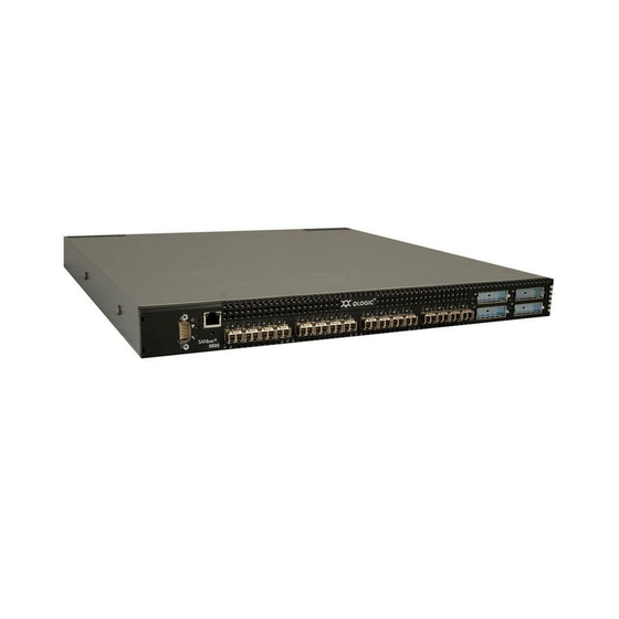
Section 2 General Description This section describes the features and capabilities of the SANbox 5000 Series Fibre Channel switches. This includes models 5200 and 5600 and the dual power supply models 5202 and 5602 as shown in Figure 2-1. The following topics are described: Chassis Controls and LEDs Fibre Channel Ports... -
Page 28: General Description Chassis Controls And Leds
2 – General Description Chassis Controls and LEDs Chassis Controls and LEDs The Maintenance button shown in Figure 2-2 is the only chassis control and is used to reset a switch or to recover a disabled switch. The chassis LEDs provide information about the switch’s operational status. -
Page 29: Placing The Switch In Maintenance Mode
2 – General Description Chassis Controls and LEDs 2.1.1.2 Placing the Switch in Maintenance Mode To place the switch in maintenance mode, do the following: Isolate the switch from the fabric. Press and hold the Maintenance button with a pointed tool for a few seconds until the Heartbeat LED alone is illuminated. -
Page 30: Input Power Led (Green)
2 – General Description Chassis Controls and LEDs 2.1.2.1 Input Power LED (Green) The Input Power LED indicates the voltage status at the switch logic circuitry. During normal operation, this LED illuminates to indicate that the switch logic circuitry is receiving the proper DC voltages. When the switch is in maintenance mode, this LED is extinguished. -
Page 31: Fibre Channel Ports
2 – General Description Fibre Channel Ports Fibre Channel Ports NOTE: This document refers to ports 0–15 as 1/2/4-Gbps ports for convenience though SANbox 5200 Series switches do not support 4-Gbps transmission. The SANbox 5000 Series switch has sixteen 1/2/4-Gbps Fibre Channel ports and four 10-Gbps Fibre Channel ports. -
Page 32: Port Leds
2 – General Description Fibre Channel Ports 2.2.1 Port LEDs Each port has its own Logged-In LED (L) and Activity LED (A) as shown in Figure 2-5. Logged-In Activity LED Logged-In Activity LED LED (Green) (Green) LED (Green) (Green) 1/2/4-Gbps Ports 10-Gbps Ports Figure 2-5. -
Page 33: Transceivers
2 – General Description Fibre Channel Ports 2.2.2 Transceivers The SANbox 5000 Series switch supports SFP optical transceivers for the 1/2/4-Gbps ports and XPAK optical transceivers for the 10-Gbps ports. A transceiver converts electrical signals to and from optical laser signals to transmit and receive data. -
Page 34: Ethernet Port
2 – General Description Ethernet Port Ethernet Port The Ethernet port is an RJ-45 connector that provides a connection to a management workstation through a 10/100 Base-T Ethernet cable. Figure 2-6 shows the Ethernet port on a model 5200/5600; the model 5202/5602 is similar. A management workstation can be a Windows®, Solaris™, or a Linux®... -
Page 35: Serial Port
2 – General Description Serial Port Serial Port The SANbox 5000 Series switch is equipped with an RS-232 serial port for maintenance purposes. Figure 2-7 shows the serial port on a model 5200/5600 switch; the model 5202/5602 is similar. You can manage the switch through the serial port using the CLI. -
Page 36: Power Supplies And Fans
2 – General Description Power Supplies and Fans Power Supplies and Fans The model 5200/5600 switch has a single power supply that converts 100–240 VAC to DC voltages for the various switch circuits. Four internal fans provide cooling. The switch monitors internal air temperature, and therefore does not monitor or report fan operational status. -
Page 37: Switch Management
2 – General Description Switch Management Switch Management The switch supports the following management tools: QuickTools Web Applet Enterprise Fabric Suite 2007 Command Line Interface Application Programming Interface Simple Network Management Protocol Storage Management Initiative–Specification (SMI-S) File Transfer Protocols 2.6.1 QuickTools Web Applet To provide basic switch management tools in a graphical user interface and to make switch management less dependent on a particular platform, each switch... -
Page 38: Enterprise Fabric Suite 2007
Application Programming Interface The Application Programming Interface (API) enables an application provider to build a management application for QLogic switches. The library is implemented in ANSI standard C, relying only on standard POSIX run-time libraries. Contact your distributor or authorized reseller for information about the API. -
Page 39: Simple Network Management Protocol
2 – General Description Switch Management 2.6.5 Simple Network Management Protocol SNMP provides monitoring and trap functions for the fabric. SANbox firmware supports SNMP versions 1 and 2, the Fibre Alliance Management Information Base (FA-MIB) version 4.0, and the Fabric Element Management Information Base (FE-MIB) RFC 2837. - Page 40 2 – General Description Switch Management Notes 2-14 59096-04 A...
-
Page 41: Planning
Section 3 Planning Consider the following when planning a fabric: Devices Device Access Performance Feature Licensing Multiple Chassis Fabrics Switch Services Fabric Security Fabric Management Devices NOTE: This document refers to ports 0–15 as 1/2/4-Gbps ports for convenience though SANbox 5200 Series switches do not support 4-Gbps transmission. -
Page 42: Device Access
3 – Planning Device Access Device Access Consider device access needs within the fabric. Access is controlled by the use of zoning. Some zoning strategies include the following: Separate devices by operating system. Separate devices that have no need to communicate with other devices in the fabric or have classified data. -
Page 43: Performance
3 – Planning Performance A zoning database is maintained on each switch. Table 3-1 describes the zoning database limits, excluding the active zone set. Table 3-1. Zoning Database Limits Limit Description MaxZoneSets Maximum number of zone sets (256). MaxZones Maximum number of zones (2000). MaxAliases Maximum number of aliases (2500). -
Page 44: Distance
3 – Planning Performance 3.3.1 Distance Consider the physical distribution of devices and switches in the fabric. Choose SFP transceivers that are compatible with the cable type, distance, Fibre Channel revision level, and the device host bus adapter. Refer to Appendix A for more information about cable types and transceivers. -
Page 45: Bandwidth
3 – Planning Performance 3.3.2 Bandwidth Bandwidth is a measure of the volume of data that can be transmitted at a given transmission rate. A 1/2/4-Gbps port can transmit or receive at nominal rates of 1-, 2-, or 4-Gbps depending on the device to which it is connected. This corresponds to full duplex bandwidth values of 212 MB, 424 MB, and 850 MB respectively. -
Page 46: Feature Licensing
3 – Planning Feature Licensing Feature Licensing NOTE: License keys enable menu selections in Enterprise Fabric Suite 2007 and commands and keywords in the CLI. License keys do not affect the capabilities of the QuickTools web applet. License keys provide a way to expand the capabilities of your switch and fabric as your needs grow. -
Page 47: Multiple Chassis Fabrics
3 – Planning Multiple Chassis Fabrics Multiple Chassis Fabrics By connecting switches together you can expand the number of available ports for devices. Each switch in the fabric is identified by a unique domain ID, and the fabric can automatically resolve domain ID conflicts. Because the Fibre Channel ports are self-configuring, you can connect SANbox 5000 Series switches together in a wide variety of topologies. -
Page 48: Domain Id, Principal Priority, And Domain Id Lock
3 – Planning Multiple Chassis Fabrics 3.5.2 Domain ID, Principal Priority, and Domain ID Lock The following switch configuration settings affect multiple chassis fabrics: Domain ID Principal priority Domain ID lock The domain ID is a unique number from 1–239 that identifies each switch in a fabric. -
Page 49: Stacking
3 – Planning Multiple Chassis Fabrics 3.5.3 Stacking You can connect up to six 20-port SANbox 5000 Series switches together through the 10-Gbps ports, thus preserving the user ports for devices. This is called stacking. The following 2-, 3-, 4-, 5-, and 6-switch stacking configurations are recommended for best performance and redundancy. -
Page 50: Four-Switch Stack
3 – Planning Multiple Chassis Fabrics Figure 3-3 shows a four-switch stack of model 5000 switches using three 3-inch and three 9-inch XPAK switch stacking cables. 64 1/2/4-Gbps ports are available for devices. Figure 3-3. Four-Switch Stack Figure 3-4 shows a five-switch stack of model 5000 switches using ten XPAK switch stacking cables. -
Page 51: Common Topologies
3 – Planning Multiple Chassis Fabrics Figure 3-5 shows a six-switch stack of model 5000 switches using eight XPAK switch stacking cables. Ninety-six 1/2/4-Gbps ports are available for devices. Figure 3-5. Six Switch Stack 3.5.4 Common Topologies The SANbox 5000 Series switch supports the following topologies using the 1/2/4-Gbps Fibre Channel ports: Cascade Topology Mesh Topology... -
Page 52: Cascade Topology
3 – Planning Multiple Chassis Fabrics 3.5.4.1 Cascade Topology A cascade topology describes a fabric in which the switches are connected in series. If you connect the last switch back to the first switch, you create a cascade-with-a-loop topology as shown in Figure 3-6. -
Page 53: Mesh Topology
3 – Planning Multiple Chassis Fabrics 3.5.4.2 Mesh Topology A mesh topology describes a fabric in which each chassis has at least one port directly connected to each other chassis in the fabric. Using 16-port SANbox 5000 Series switches the mesh fabric shown in Figure 3-7 has the following characteristics:... -
Page 54: Multistage Topology
3 – Planning Multiple Chassis Fabrics 3.5.4.3 MultiStage Topology Each link contributes up to 425 MB of bandwidth between chassis. Competition for this bandwidth is less than that of a cascade topology, but greater than that of the mesh topology. Latency between any two ports is no more than two chassis hops. -
Page 55: Switch Services
3 – Planning Switch Services Switch Services You can configure your switch to suit the demands of your environment by enabling or disabling a variety of switch services. Familiarize yourself with the following switch services and determine which ones you need. Notice that the SSH and SSL services require the Fabric Security license key. -
Page 56: Fabric Security
3 – Planning Fabric Security Common Information Model (CIM): Provides for the management of the switch through third-party applications that use the Storage Management Initiative–Specification (SMI-S). The default is enabled. File Transfer Protocol (FTP): Provides for transferring files rapidly between the workstation and the switch using FTP. -
Page 57: Connection Security
3 – Planning Fabric Security 3.7.1 Connection Security NOTE: You must install the Fabric Security license key to secure connections using SSH and SSL. Connection security provides an encrypted data path for switch management methods. The switch supports the Secure Shell (SSH) protocol for the command line interface and the Secure Socket Layer (SSL) protocol for management applications such as Enterprise Fabric Suite 2007 and SMI-S. -
Page 58: Port Binding
3 – Planning Fabric Security Authentication of the user account and password can be performed locally using the switch’s user account database or it can be done remotely using a RADIUS server such as Microsoft® RADIUS. Authenticating user logins on a RADIUS server requires a secure management connection to the switch. -
Page 59: Device Security
3 – Planning Fabric Security 3.7.4 Device Security NOTE: You must install the Fabric Security license key to configure and activate device security and RADIUS servers. If you are upgrading your switch firmware to version 6.7 from version 5.x, you are granted a 30-day temporary license. -
Page 60: Security Example: Switches And Hbas With Authentication
3 – Planning Fabric Security Consider the devices, switches, and management agents and evaluate the need for authorization and authentication. Also consider whether the security database is to distributed on the switches or centralized on a RADIUS server and how many servers to configure. - Page 61 3 – Planning Fabric Security Create a security set (Security_Set_1) on Switch_1. Create a port group (Group_Port_1) in Security_Set_1 with Switch_1, HBA_1, and JBOD as members. Port Group on Switch_1: Group_Port_1 Switch_1 Node WWN: 10:00:00:c0:dd:07:e3:4c Authentication: CHAP Primary Hash: MD5 Primary Secret: 0123456789abcdef HBA_1 Node WWN: 10:00:00:c0:dd:07:c3:4d...
- Page 62 3 – Planning Fabric Security Create an ISL group (Group_ISL_1) in Security_Set_1 with Switch_1, Switch_2, HBA1, and JBOD as members. The Switch_1 secret must be shared with the Switch_2 security database. ISL Group on Switch_1: Group_ISL_1 Switch_1 Node WWN: 10:00:00:c0:dd:07:e3:4c Authentication: CHAP Primary Hash: MD5 Primary Secret: 0123456789abcdef...
-
Page 63: Security Example: Radius Server
3 – Planning Fabric Security 3.7.4.2 Security Example: RADIUS Server Consider the fabric shown in Figure 3-10. This fabric is similar to the one shown in Figure 3-9 with the addition of Radius_1 acting as a RADIUS server. Authorization and authentication is passed from the switch to Radius_1 in the following cases: HBA_1 login to Switch_1 Switch_1 login to Switch_2 Switch_2 login to Switch_1... - Page 64 3 – Planning Fabric Security Configure the Radius_1 host as a RADIUS server on Switch_1 and Switch_2 to authenticate device logins. Specify the server IP address and the secret with which the switches will authenticate with the server. Configure the switches so that devices authenticate through the switches only if the RADIUS server is unavailable.
- Page 65 3 – Planning Fabric Security Create a security set (Security_Set_1) on Switch_1. Create a port group (Group_Port_1) in Security_Set_1 with Switch_1 and HBA_1 as members. Port Group on Switch_1: Group_Port_1 Switch_1 Node WWN: 10:00:00:c0:dd:07:e3:4c Authentication: CHAP Primary Hash: MD5 Primary Secret: 0123456789abcdef HBA_1 Node WWN: 10:00:00:c0:dd:07:c3:4d Authentication: CHAP...
- Page 66 3 – Planning Fabric Security Create an ISL group (Group_ISL_1) in Security_Set_1 with Switch_1 and Switch_2 as members. The Switch_1 secret must be shared with the Switch_2 security database. ISL Group on Switch_1: Group_ISL_1 Switch_1 Node WWN: 10:00:00:c0:dd:07:e3:4c Authentication: CHAP Primary Hash: MD5 Primary Secret: 0123456789abcdef Binding: None...
-
Page 67: Security Example: Host Authentication
3 – Planning Fabric Security 3.7.4.3 Security Example: Host Authentication Consider the fabric shown in Figure 3-11. In this fabric, only Switch_2 and HBA_2/APP_2 support security, where APP_2 is a host application. The objective is to secure the management server on Switch_2 from unauthorized access by an HBA or an associated host application. - Page 68 3 – Planning Fabric Security Create a security set (Security_Set_2) on Switch_2. Create a Management Server group (Group_1) in Security_Set_2 with Switch_2 and HBA_2 or APP_2 as its member. You must specify HBAs by node worldwide name. Switches can be specified by port or node worldwide name.
-
Page 69: Fabric Management
3 – Planning Fabric Management Fabric Management The Enterprise Fabric Suite 2007 application executes on a management workstation and provides for the configuration, control, and maintenance of multiple fabrics. Supported platforms include Windows, Solaris, Linux, and MacOS X. Enterprise Fabric Suite 2007 comes with a 30-day trial license – a permanent license is available for purchase from your authorized reseller. - Page 70 3 – Planning Fabric Management Notes 3-30 59096-04 A...
-
Page 71: Installation
Section 4 Installation This section describes how to install and configure the switch. The following topics are covered: Site Requirements Installing a Switch Installing Firmware Adding a Switch to an Existing Fabric Installing Feature License Keys Site Requirements Consider the following items when installing a SANbox 5000 Series switch: Fabric Management Workstation Switch Power Requirements Environmental Conditions... -
Page 72: Fabric Management Workstation
4 – Installation Site Requirements 4.1.1 Fabric Management Workstation The requirements for fabric management workstations are described in Table 4-1: Table 4-1. Management Workstation Requirements Windows 2003 SP1/SP2, XP Operating System Solaris 9, 10, 10 x86 Red Hat® Enterprise Linux® 3, 4 SUSE™... -
Page 73: Installing A Switch
4 – Installation Installing a Switch Installing a Switch Unpack the switch and accessories. The SANbox 5000 Series product is shipped with the components shown in Figure 4-1: SANbox 5000 Series Fibre Channel Switch (1) with firmware installed Power cords (1) –model 5200/5600 (2) –model 5202/5602 Rubber feet (4) -
Page 74: Mount The Switch
P.O. Box 39100 Indianapolis, IN 46239-0100 317-897-7000 www.generaldevices.com A model 5202/5602 switch requires a QLogic rail kit (part numbers SB5202-RACKKIT and SB5602-RACKKIT) for rack mounting. WARNING!! Mount switches in the rack so that the weight is distributed evenly. An unevenly loaded rack can become unstable possibly resulting in equipment damage or personal injury. -
Page 75: Mounting The Model 5200/5600 Switch In A Rack Without Rails
4 – Installation Installing a Switch WARNING!! If the switch is mounted in a closed or multi-rack assembly, the operating temperature of the rack environment may be greater than the ambient temperature. Be sure to install the chassis in an environment that is compatible with the maximum rated ambient temperature. -
Page 76: Install Transceivers
4 – Installation Installing a Switch To mount a model 5200/5600 switch in a rack using the General Devices C-874 rail kit, you must fasten the switch brackets and inner rails to the switch as shown Figure 4-3. Use the screws that come with the rail kit. Refer to the rail kit instructions for complete information. -
Page 77: Removing 10-Gbps Port Covers
4 – Installation Installing a Switch If you are using the 10-Gbps ports, remove the port covers by the cover tabs using your fingers or pliers as shown in Figure 4-4. Figure 4-4. Removing 10-Gbps Port Covers To install XPAK switch stacking cables, position the cable connectors with the circuit board toward the mid line of the respective switch faceplates as shown in Figure 4-5. -
Page 78: Configure The Workstation
4 – Installation Installing a Switch 4.2.3 Configure the Workstation If you plan to use the command line interface to configure and manage the switch, you must configure the workstation. This involves setting the workstation IP address for Ethernet connections, or configuring the workstation serial port. If you plan to use QuickTools or Enterprise Fabric Suite 2007 to manage the switch, the Configuration Wizard manages the workstation IP address for you –... -
Page 79: Configuring The Workstation Serial Port
4 – Installation Installing a Switch 4.2.3.2 Configuring the Workstation Serial Port To configure the workstation serial port, do the following: Connect a null modem F/F DB9 cable from a COM port on the management workstation to the RS-232 serial port on the switch. Configure the workstation serial port according to your platform: For Windows: Open the HyperTerminal application. -
Page 80: Connect The Workstation To The Switch
4 – Installation Installing a Switch 4.2.4 Connect the Workstation to the Switch You can manage the switch using the CLI, QuickTools, or Enterprise Fabric Suite 2007. QuickTools and Enterprise Fabric Suite 2007 require an Ethernet connection to the switch. The CLI can use an Ethernet connection or a serial connection. -
Page 81: Connect The Switch To Ac Power
4 – Installation Installing a Switch 4.2.5 Connect the Switch to AC Power WARNING!! This product is supplied with a 3-wire power cable and plug for the user’s safety. Use this power cable in conjunction with a properly grounded outlet to avoid electrical shock. An electrical outlet that is not correctly wired could place hazardous voltage on metal parts of the switch chassis. - Page 82 4 – Installation Installing a Switch WARNUNG!! Dieses Produkt wird mit einem 3-adrigen Netzkabel mit Stecker geliefert. Dieses Kabel erfüllt die Sicherheitsanforderungen und sollte an einer vorschriftsmäßigen Schukosteckdose angeschlossen werden, um die Gefahr eines elektrischen Schlages zu vermeiden.Elektrosteckdosen, die nicht richtig verdrahtet sind, können gefährliche Hochspannung an den Metallteilen des switch-Gehäuses verursachen.
- Page 83 4 – Installation Installing a Switch To power up a SANbox 5000 Series switch, do the following: For a model 5200/5600 switch, connect the power cord to the AC power receptacle on the front of the switch chassis and to a grounded AC outlet. For a model 5202/5602 switch, connect the power cords to the power supply receptacles on the back of the switch chassis and to a grounded AC outlet.
-
Page 84: Configure The Switch
4 – Installation Installing a Switch 4.2.6 Configure the Switch You can configure the switch using the CLI, QuickTools, or Enterprise Fabric Suite 2007. Enterprise Fabric Suite 2007 is an optional, full fabric graphical user interface that comes with a 30-day trial license. Refer to the SANbox 5000 Series Enterprise Fabric Suite 2007 User Guide for information about installing Enterprise Fabric Suite 2007. - Page 85 4 – Installation Installing a Switch To configure the switch using the command line interface, do the following: Open a command window according to the type of workstation and connection: Ethernet (all platforms): Open a Telnet session with the default switch IP address and log in to the switch with default account name and password (admin/password).
-
Page 86: Cable Devices To The Switch
4 – Installation Installing Firmware 4.2.7 Cable Devices to the Switch Connect cables to the SFP transceivers and their corresponding devices, and then energize the devices. Device host bus adapters can have SFP (or SFF) transceivers or GigaBit Interface Converters (GBIC). LC-type duplex fiber optic cable connectors are designed for SFP transceivers, while SC-type connectors are designed for GBICs. - Page 87 4 – Installation Installing Firmware NOTE: You can load and activate version 6.7 firmware on an operating switch without disrupting data traffic or having to re-initialize attached devices. If you attempt to perform a non-disruptive activation without satisfying the following conditions, the activation will fail. If the non-disruptive activation fails, you will usually be prompted to try again later.
-
Page 88: Using Quicktools To Install Firmware
4 – Installation Installing Firmware 4.3.1 Using QuickTools to Install Firmware To install firmware using QuickTools, do the following: In the faceplate display, open the Switch menu and select Load Firmware. In the Firmware Upload dialog, click the Browse button to browse and select the firmware file to be uploaded. - Page 89 4 – Installation Installing Firmware Refer to the SANbox 5000 Series Fibre Channel Switch Command Line Interface Guide for information about the CLI commands. Enter the following commands to download the firmware from a remote host to the switch, install the firmware, then reset the switch to activate the firmware.
-
Page 90: Custom Firmware Installation
4 – Installation Installing Firmware 4.3.2.2 Custom Firmware Installation A custom firmware installation downloads the firmware image file from an FTP or TFTP server to the switch, unpacks the image file, and resets the switch in separate steps. This allows you to choose the type of switch reset and whether the activation will be disruptive (Reset Switch command) or nondisruptive (Hotreset command). -
Page 91: Adding A Switch To An Existing Fabric
4 – Installation Adding a Switch to an Existing Fabric Adding a Switch to an Existing Fabric If there are no special conditions to be configured for the new switch, simply plug in the switch and the switch becomes functional with the default fabric configuration. - Page 92 4 – Installation Installing Feature License Keys Notes 4-22 59096-04 A...
-
Page 93: Diagnostics/Troubleshooting
Section 5 Diagnostics/Troubleshooting Diagnostic information about the switch is available through the chassis LEDs and the port LEDs. Diagnostic information is also available through the CLI, QuickTools, or Enterprise Fabric Suite 2007 event logs and error displays. This section describes the following types of diagnostics: Chassis Diagnostics describes the Input Power LED and System Fault LED indications. -
Page 94: Input Power Led Is Extinguished
5 – Diagnostics/Troubleshooting Chassis Diagnostics 5.1.1 Input Power LED Is Extinguished The Input Power LED illuminates to indicate that the switch logic circuitry is receiving proper voltages. If the Input Power LED is extinguished, do the following: Inspect the power cords and connectors. Is the cord unplugged? Is the cord or connector damaged? Yes - Make necessary corrections or repairs. -
Page 95: Power-On Self Test Diagnostics
5 – Diagnostics/Troubleshooting Power-On Self Test Diagnostics Power-On Self Test Diagnostics The switch performs a series of tests as part of its power-up procedure. The POST diagnostic program performs the following tests: Checksum tests on the boot firmware in PROM and the switch firmware in flash memory Internal data loopback test on all ports Access and integrity test on the ASIC... -
Page 96: Internal Firmware Failure Blink Pattern
5 – Diagnostics/Troubleshooting Power-On Self Test Diagnostics 5.2.1.1 Internal Firmware Failure Blink Pattern An internal firmware failure blink pattern is 2 blinks followed by a two second pause. The 2-blink error pattern indicates that the firmware has failed, and that the switch must be reset. -
Page 97: Configuration File System Error Blink Pattern
5 – Diagnostics/Troubleshooting Power-On Self Test Diagnostics 5.2.1.3 Configuration File System Error Blink Pattern A configuration file system error blink pattern is 4 blinks followed by a two second pause. The 4-blink error pattern indicates that a configuration file system error has occurred, and that the configuration file must be restored. -
Page 98: Over Temperature Blink Pattern
5 – Diagnostics/Troubleshooting Power-On Self Test Diagnostics 5.2.1.4 Over Temperature Blink Pattern An over temperature blink pattern is 5 blinks followed by a two second pause. The 5-blink error pattern indicates that the air temperature inside the switch has exceeded the failure temperature threshold. 2 seconds If the Heartbeat LED shows the over temperature blink pattern, do the following: Inspect the chassis vents. -
Page 99: Logged-In Led Indications
5 – Diagnostics/Troubleshooting Power-On Self Test Diagnostics 5.2.2 Logged-In LED Indications Port diagnostics are indicated by the Logged-In LED for each port as shown in Figure 5-2. Logged-In LED Figure 5-2. Logged-In LED The Logged-In LED has three indications: Continuous illumination: A device is logged in to the port. Flashing once per second: A device is logging in to the port, or the port is in the diagnostics state. -
Page 100: E_Port Isolation
5 – Diagnostics/Troubleshooting Power-On Self Test Diagnostics 5.2.2.1 E_Port Isolation A Logged-In LED error indication is often the result of E_Port isolation. E_Port isolation can be caused by the following: Security failure FL_Port is connected to another switch Conflicting domain IDs Conflicting timeout values Conflicting zone membership between active zone sets Review the event browser and do the following to diagnose and correct an... -
Page 101: Excessive Port Errors
5 – Diagnostics/Troubleshooting Power-On Self Test Diagnostics Compare the RA_TOV and ED_TOV timeout values for all switches in the fabric using the Show Config Switch command. Is each timeout value the same on every switch? Yes - Continue. No - Correct the timeout values on the offending switches using the Set Config Switch CLI. - Page 102 5 – Diagnostics/Troubleshooting Power-On Self Test Diagnostics If the count for any of these errors exceeds the rising trigger for three consecutive sample windows, the switch generates an alarm and disables the affected port, changing its operational state to “down”. Port errors can be caused by the following: Triggers are too low or the sample window is too small Faulty Fibre Channel port cable...
-
Page 103: Transceiver Diagnostics
5 – Diagnostics/Troubleshooting Transceiver Diagnostics Transceiver Diagnostics NOTE: Transceiver diagnostic information is available with purchase of the SANdoctor license key. To purchase a license key, contact your authorized maintenance provider. You can display the following transceiver information using the Show Media CLI command: Port number Manufacturer... -
Page 104: Power Supply Diagnostics
5 – Diagnostics/Troubleshooting Power Supply Diagnostics Power Supply Diagnostics A model 5202/5602 switch power supply has a Status LED (Green) and a Fault LED (Amber) as shown in Figure 5-3. Under normal operating conditions, the Power Supply Status LED is illuminated and the Power Supply Fault LED is extinguished. -
Page 105: Recovering A Switch Using Maintenance Mode
5 – Diagnostics/Troubleshooting Recovering a Switch Using Maintenance Mode Recovering a Switch Using Maintenance Mode A switch can become inoperable or unmanageable for the following reasons: Firmware becomes corrupt IP address is lost Switch configuration becomes corrupt Forgotten password In these specific cases, you can recover the switch using maintenance mode. Maintenance mode temporarily returns the switch IP address to 10.0.0.1 and provides opportunities to do the following: Exiting the Maintenance Menu... -
Page 106: Exiting The Maintenance Menu
5 – Diagnostics/Troubleshooting Recovering a Switch Using Maintenance Mode The maintenance menu displays several recovery options. To select a switch recovery option, press the corresponding number (displayed in option: field) on the keyboard and press the Enter key. Exit Image Unpack Reset Network Config Reset User Accounts to Default Copy Log Files... -
Page 107: Resetting The Network Configuration In Maintenance Mode
5 – Diagnostics/Troubleshooting Recovering a Switch Using Maintenance Mode Select option 1 from the maintenance menu. When prompted for a file name prompt, enter the firmware image file name. Image filename: filename Unpacking ’filename’, please wait... Unpackage successful. Select option 7 to reset the switch and exit maintenance mode. 5.5.3 Resetting the Network Configuration in Maintenance Mode This option resets the network properties to the factory default values and saves... -
Page 108: Remaking The File System In Maintenance Mode
5 – Diagnostics/Troubleshooting Recovering a Switch Using Maintenance Mode 5.5.7 Remaking the File System in Maintenance Mode In the event of a loss of power, the switch configuration may become corrupt. The file system on which the configuration is stored must be re-created. This option resets the switch to the factory default values including user accounts and zoning. -
Page 109: Removal/Replacement
Section 6 Removal/Replacement This section describes the removal and replacement procedures for the following field replaceable units (FRU): SFP transceivers Power supplies for model 5202/5602 switches The switch is equipped with a battery that powers the non-volatile memory. This memory stores the switch configuration. The battery is not a field replaceable unit. WARNING!! Danger of explosion if battery is incorrectly replaced. -
Page 110: Power Supply Removal And Replacement
6 – Removal/Replacement Power Supply Removal and Replacement Power Supply Removal and Replacement The SANbox 5202/5602 power supplies are hot pluggable. This means you can remove or install one of the power supplies while the switch is operating without disrupting service. The power supplies are also interchangeable; that is, the left and right power supplies are the same unit. -
Page 111: Power Supply Installation
6 – Removal/Replacement Power Supply Removal and Replacement Confirm that the Heartbeat LED is showing the normal 1 blink per second. This allows the switch to correctly report power supply status. Confirm that the new power supply is compatible with the switch air flow direction. - Page 112 6 – Removal/Replacement Power Supply Removal and Replacement Notes 59096-04 A...
-
Page 113: Appendix A Specifications
Appendix A Specifications This appendix contains the specifications for the SANbox 5000 Series Fibre Channel switch. Refer to Section 2 for the location of all connections, switches, controls, and components. Fabric Specifications Fibre Channel Protocols ....FC-PH Rev. 4.3 FC-PH-2 FC-PH-3 FC-AL Rev 4.6 FC-AL-2 Rev 7.0... - Page 114 A – Specifications Fabric Specifications Number of Fibre Channel Ports ..Variable and can be upgraded in the following configurations: (5200 Series models do not support 4-Gbps) Eight 1/2/4-Gbps FC ports Twelve 1/2/4-Gbps FC ports Sixteen 1/2/4-Gbps FC ports Sixteen 1/2/4-Gbps FC ports plus four 10-Gbps FC ports Scalability........
-
Page 115: Maintainability
A – Specifications Maintainability Bandwidth Point-to-Point ......... 212 MB, Full Duplex @ 1-Gbps 224 MB, Full Duplex @ 2-Gbps 850 MB, Full Duplex @ 4-Gbps Aggregate (single switch) ....2550 MB, Full Duplex @ 10-Gbps Up to 23.80 GB Full Duplex Bandwidth Point-to-Point ......... -
Page 116: Fabric Management
A – Specifications Fabric Management Fabric Management Management Methods ....Enterprise Fabric Suite 2007 graphical user interface QuickTools web applet Command Line Interface Application Programming Interface SMI-S GS-3 Management Server SNMP TFTP Maintenance Connection ....RS-232 connector; null modem F/F DB9 cable Ethernet Connection ....... -
Page 117: Electrical
A – Specifications Electrical Electrical Operating voltage ......100 to 240 VAC; 50 to 60 Hz Power source loading (maximum) .. 1 A at 120 VAC 0.5 A at 240 VAC Heat Output (maximum) ....100 watts Circuit Protection ......Internally fused Environmental Temperature Operating ........ -
Page 118: Regulatory Certifications
A – Specifications Regulatory Certifications Regulatory Certifications Safety Standards ......UL60950:2000 CSA 22.2 No. 60950-00 (Canada) EN60950 (EC) CB Scheme-IEC 60950 Emissions Standards ...... FCC Part 15B Class A ICES-03 Issue 3 VCCI Class A ITE CISPR 22, Class A EN 55022, Class A Voltage Fluctuations ....... - Page 119 Glossary Access Control List Zone Arbitrated Loop Access Control List zoning divides the A Fibre Channel topology where ports use fabric for purposes of controlling discovery arbitration to establish a point-to-point and inbound traffic. circuit. Active Zone Set Arbitrated Loop Physical Address (AL_PA) The zone set that defines the current A unique one-byte value assigned during zoning for the fabric.
- Page 120 SANbox 5000 Series Fibre Channel Switch Installation Guide Class 2 Service Expansion Port A service which multiplexes frames at E_Port that connects to another FC-SW-2 frame boundaries to or from one or more compliant switch. N_Ports wit h acknowledgment provided. Fabric Database Chassis Hop The set of fabrics that have been opened...
- Page 121 SANbox 5000 Series Fibre Channel Switch Installation Guide Flash Memory Input Power LED Memory on the switch that contains the A chassis LED that indicates that the chassis control firmware. switch logic circuitry is receiving proper DC voltages. Frame Inter-Switch Link Data unit consisting of a start-of-frame (SOF) delimiter, header, data payload, The connection between two switches...
- Page 122 SANbox 5000 Series Fibre Channel Switch Installation Guide Simple Network Management Protocol Management Information Base An application protocol that manages and monitors network communications and Multistage Topology functions. It also controls the Management Information Base (MIB). A fabric in which two or more edge switches connect to one or more core Security Set switches.
- Page 123 SANbox 5000 Series Fibre Channel Switch Installation Guide Voluntary Control Council for Interference A consortium of Japanese electronics industry associations that have established voluntary standards for controlling electromagnetic interference (EMI). Worldwide Name (WWN) A unique 64-bit address assigned to a device by the device manufacturer.
- Page 124 SANbox 5000 Series Fibre Channel Switch Installation Guide Notes Glossary-6 59096-04 A...
- Page 125 Index Numerics chassis air flow A-5 10/100 Base-T straight cable 4-10 diagnostics 5-1 10-Gbps port 2-5 LEDs 2-3 marking A-6 shock A-5 vibration A-5 classes of service A-1 account name command line interface 2-12 default 4-14 Common Information Model 3-16 FTP 4-20 configuration maintenance mode 5-13...
- Page 126 SANbox 5000 Series Fibre Channel Switch Installation Guide firmware description 4-16 E_Port 2-7, 5-8 failure 5-4 emissions standards A-6 install with CLI 4-18 Enterprise Fabric Suite 2007 2-12 install with QuickTools 4-18 environmental non-disruptive activation 4-17 conditions 4-2 unpack image 5-14 specifications A-5 five-switch stacking 3-10 error...
- Page 127 SANbox 5000 Series Fibre Channel Switch Installation Guide latency 3-5, A-2 operating systems 4-2 over temperature 5-6 Activity 2-6, 2-8 Heartbeat 2-4, 5-3 Input Power 2-4, 5-2 Link Status 2-8 password Logged-In 2-6, 5-7 file reset 5-15 power supply 2-10 maintenance mode 5-13 System Fault 2-4, 5-2 restore default 5-15...
- Page 128 SANbox 5000 Series Fibre Channel Switch Installation Guide Power-on Self Test security description 5-3 certificate 3-17 fatal error 5-4 connection 3-17 principal database limits 3-19 priority 3-8 device 3-19 switch 3-8 fabric 3-16 processor 4-2, A-2 user account 3-17 serial port 2-9, 4-9, 4-10 SFP - See Small Form-Factor Pluggable shock A-5 Simple Network Management Protocol...
- Page 129 SANbox 5000 Series Fibre Channel Switch Installation Guide Telnet service 3-15 temperature zone error 5-6 conflict 5-9 operating range 4-2, A-5 definition 3-2 three-switch-stacking 3-9 zone set timeout values 5-9 active 3-2 topology definition 3-2 cascade 3-12 zoning mesh 3-13 database 3-3 transceiver 2-7, 4-6, 6-1 hardware enforced 3-2...
- Page 130 SANbox 5000 Series Fibre Channel Switch Installation Guide Notes Index-6 59096-04 A...
Need help?
Do you have a question about the SANbox 5000 Series and is the answer not in the manual?
Questions and answers