Qlogic SANbox 3810 Installation Manual
Fibre channel switch
Hide thumbs
Also See for SANbox 3810:
- Interface manual (396 pages) ,
- User manual (142 pages) ,
- Quick start manual (4 pages)
Table of Contents
Advertisement
Quick Links
Download this manual
See also:
User Manual
Advertisement
Table of Contents

Related Manuals for Qlogic SANbox 3810


Summary of Contents for Qlogic SANbox 3810
- Page 1 SANbox 3810 Fibre Channel Switch Installation Guide Firmware Version 7.4 59268-00 A...
-
Page 2: Document Revision History
QLogic Corporation reserves the right to change product specifications at any time without notice. Applications described in this document for any of these products are for illustrative purposes only. QLogic Corporation makes no representation nor warranty that such applications are suitable for the specified use without further testing or modification. -
Page 3: Table Of Contents
Table of Contents Preface Intended Audience ..........Related Materials . - Page 4 SANbox 3810 Fibre Channel Switch Installation Guide General Description Chassis Controls and LEDs ........Input Power LED (Green) .
- Page 5 SANbox 3810 Fibre Channel Switch Installation Guide Fabric Management ......... . . Installation Site Requirements .
- Page 6 SANbox 3810 Fibre Channel Switch Installation Guide Resetting the Network Configuration in Maintenance Mode (Option 2) ..........Resetting User Accounts in Maintenance Mode (Option 3).
- Page 7 SANbox 3810 Fibre Channel Switch Installation Guide List of Tables Table Page Serial Port Pin Identification ......... . . Zoning Database Limits .
- Page 8 SANbox 3810 Fibre Channel Switch Installation Guide Notes viii 59268-00 A...
-
Page 9: Preface
Preface This manual describes the features and installation of the SANbox 3810 Fibre ® Channel switch, firmware version 7.4. The SANbox 3810 switch is an 8-port, 8-Gbps Fibre Channel switch with a single power supply. This manual is organized as follows: Section 1 is an overview of the switch. -
Page 10: Related Materials
SANbox Simple Network Management Protocol Reference Guide, publication number, 59047-10 CIM Agent Reference Guide, publication number 59223-03 QLogic Switch Interoperability Guide v3.0. This PDF document can be downloaded at http://www.qlogic.com/interopguide/info.asp#inter. Fibre Channel-Arbitrated Loop (FC-AL-2) Rev. 6.8 Fibre Channel-10-bit Interface Rev. 2.3. -
Page 11: Safety Notices
Preface Safety Notices Safety Notices A Warning notice indicates the presence of a hazard that has the potential of causing personal injury. 3-4, A Caution notice indicates the presence of a hazard that has the potential of causing damage to the equipment. 3-5, 4-10 Sicherheitshinweise... -
Page 12: Communications Statements
Preface Communications Statements Communications Statements The following statements apply to this product. The statements for other products intended for use with this product appear in their accompanying manuals. Federal Communications Commission (FCC) Class A Statement This equipment has been tested and found to comply with the limits for a Class A digital device, pursuant to Part 15 of the FCC Rules. -
Page 13: Ce Statement
Preface Communications Statements CE Statement The CE symbol on the equipment indicates that this system complies with the EMC (Electromagnetic Compatibility) directive of the European Community (2004/108/EC) and to the Low Voltage (Safety) Directive (2006/95/EC). Such marking indicates that this system meets or exceeds the following technical standards: EN 60950-1:2001 –... -
Page 14: Vcci Class A Statement
Preface Laser Safety Information VCCI Class A Statement This is a Class A product based on the standard of the Voluntary Control Council For Interference by Information Technology Equipment (VCCI). If this equipment is used in a domestic environment, radio disturbance may arise. When such trouble occurs, the user may be required to take corrective actions. -
Page 15: Accessible Parts
Preface Accessible Parts Accessible Parts The Field Replaceable Units (FRUs) for the SANbox 3810 switch are the following: Small Form-Factor Pluggable (SFP) optical transceivers Pièces Accessibles Les pièces remplaçables, Field Replaceable Units (FRU), du commutateur SANbox 3810 Fibre Channel Switch sont les suivantes: Interfaces aux media d’interconnexion appelés SFP transceivers Zugängliche Teile Nur die folgenden Teile im SANbox 3810 Fibre Channel Switch können... -
Page 16: General Public License
General Public License General Public License QLogic® Fibre Channel switches are powered by the Linux operating system. A machine-readable copy of the Linux source code is available upon written request to the following address. A nominal fee will be charged for reproduction, shipping, and handling costs in accordance with the General Public License. -
Page 17: Terms And Conditions For Copying, Distribution And Modification
Preface General Public License We protect your rights with two steps: (1) copyright the software, and (2) offer you this license which gives you legal permission to copy, distribute and/or modify the software. Also, for each author's protection and ours, we want to make certain that everyone understands that there is no warranty for this free software. - Page 18 Preface General Public License You may modify your copy or copies of the Program or any portion of it, thus forming a work based on the Program, and copy and distribute such modifications or work under the terms of Section 1 above, provided that you also meet all of these conditions: You must cause the modified files to carry prominent notices stating that you changed the files and the date of any change.
- Page 19 Preface General Public License and 2 above on a medium customarily used for software interchange; Accompany it with a written offer, valid for at least three years, to give any third party, for a charge no more than your cost of physically performing source distribution, a complete machine-readable copy of the corresponding source code, to be distributed under the terms of Sections 1 and 2 above on a medium customarily used for software...
- Page 20 Preface General Public License Each time you redistribute the Program (or any work based on the Program), the recipient automatically receives a license from the original licensor to copy, distribute or modify the Program subject to these terms and conditions. You may not impose any further restrictions on the recipients' exercise of the rights granted herein.
-
Page 21: How To Apply These Terms To Your New Programs
Preface General Public License Each version is given a distinguishing version number. If the Program specifies a version number of this License which applies to it and "any later version", you have the option of following the terms and conditions either of that version or of any later version published by the Free Software Foundation. - Page 22 Preface General Public License To do so, attach the following notices to the program. It is safest to attach them to the start of each source file to most effectively convey the exclusion of warranty; and each file should have at least the "copyright" line and a pointer to where the full notice is found.
-
Page 23: Qfsapp Program License
Preface qfsApp Program License Yoyodyne, Inc., hereby disclaims all copyright interest in the program `Gnomovision' (which makes passes at compilers) written by James Hacker. signature of Ty Coon, 1 April 1989 Ty Coon, President of Vice This General Public License does not permit incorporating your program into proprietary programs. -
Page 24: Technical Support
Fibre Channel products. From the main QLogic web page at www.qlogic.com, click the Education and Resources tab at the top, then click the Education & Training tab on the left. The QLogic Global Training Portal offers online courses, certification exams, and scheduling of in-person training. -
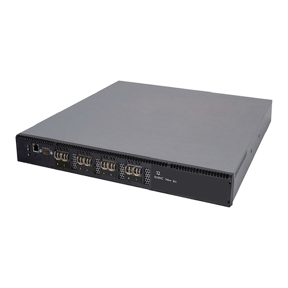
Page 25: General Description
General Description The SANbox 3810 switch, shown in Figure 1-1, is an 8-port, 8-Gbps Fibre Channel switch with both Ethernet and serial management interfaces. This switch is designed to be a standalone switch that cannot be connected to other switches. This section describes the features and capabilities of the SANbox 3810 switch including the following: Chassis Controls and LEDs... -
Page 26: Chassis Controls And Leds
General Description Chassis Controls and LEDs The switch is managed with the Command Line Interface (CLI) or the QuickTools web applet. Refer to SANbox 3810 Fibre Channel Switch Command Line Interface Guide for more information about the CLI. Refer to the SANbox 3810 QuickTools Switch Management User Guide for information about QuickTools. -
Page 27: Heartbeat Led (Green)
General Description Chassis Controls and LEDs Heartbeat LED (Green) The Heartbeat LED indicates the status of the internal switch processor and the results of the POST. Following a normal power-up, the Heartbeat LED blinks about once per second to indicate that the switch passed the POST and that the internal switch processor is running. -
Page 28: Fibre Channel Ports
General Description Fibre Channel Ports Fibre Channel Ports The SANbox 3810 switch has eight Fibre Channel Small Form-Factor Pluggable (SFP) ports. The SFP ports are numbered 0–7 as shown in Figure 1-3. Each SFP port is served by an SFP optical transceiver and is capable of 1-, 2-, 4-, or 8-Gbps transmission. -
Page 29: Port Logged-In Led (Green)
General Description Fibre Channel Ports Port Logged-In LED (Green) The Logged-in LED indicates the logged-in or initialization status of the connected devices. After successful completion of the POST, the switch extinguishes all Logged-In LEDs. Following a successful port login, the switch illuminates the corresponding logged-in LED. -
Page 30: Ethernet Port
General Description Ethernet Port Ethernet Port The Ethernet port is an RJ-45 connector that provides a connection to a management workstation through a 10/100 Base-T Ethernet cable as shown in Figure 1-5. A management workstation can be a Windows®, Solaris™, or a Linux®... -
Page 31: Serial Port
General Description Serial Port Serial Port The SANbox 3810 switch is equipped with an RS-232 serial port for maintenance purposes as shown in Figure 1-6. You can manage the switch through the serial port using the CLI. RS-232 Connector Pin Identification Serial Port Figure 1-6 Serial Port and Pin Identification The serial port requires a null-modem F/F DB9 cable. -
Page 32: Power Supplies And Fans
General Description Power Supplies and Fans Power Supplies and Fans The SANbox 3810 switch has a single power supply that converts 100–240 VAC to DC voltages for the various switch circuits. Internal fans provide cooling. The switch monitors internal air temperature, and therefore does not monitor or report fan operational status. -
Page 33: Command Line Interface
Application Programming Interface The Application Programming Interface (API) enables an application provider to build a management application for QLogic switches. The library is implemented in ANSI standard C, relying only on standard POSIX run-time libraries. Contact your distributor or authorized reseller for information about the API. - Page 34 General Description Switch Management Notes 1-10 59268-00 A...
-
Page 35: Planning
Planning Consider the following when planning a fabric: Devices Device Access Performance Switch Services Internet Protocol Support Security Fabric Management Devices When planning a fabric, consider the number of devices and the anticipated demand. This will determine the number of ports that are needed and in turn the number of switches. -
Page 36: Device Access
Planning Device Access Device Access Consider device access needs within the fabric. Access is controlled by the use of zoning. Some zoning strategies include the following: Separate devices by operating system. Separate devices that have no need to communicate with other devices in the fabric or have classified data. -
Page 37: Performance
Planning Performance Performance The SANbox 3810 switch supports class 2 and class 3 Fibre Channel service at transmission rates of 1-, 2-, 4-, and 8-Gbps with a maximum frame size of 2148 bytes. Each Fibre Channel port adapts its transmission speed to match that of the device to which it is connected prior to login when the connected device powers up. -
Page 38: Latency
Planning Switch Services Latency Latency is a measure of how fast a frame travels through a switch from one port to another. The factors that affect latency include transmission rate and the source/destination port relationship as shown in Table 2-2. Table 2-2. - Page 39 Planning Switch Services Secure Socket Layer (SSL): Provides for secure SSL connections for the QuickTools web applet, the API, and SMI-S. To enable secure SSL connections, you must first synchronize the date and time on the switch and workstation. Enabling SSL automatically creates a security certificate on the switch.
-
Page 40: Internet Protocol Support
Planning Internet Protocol Support Furthermore, you can configure periodic event data collection and processing through the Tech_Support_Center profile for automated status and trend analysis. Internet Protocol Support The switch supports IP version 4, IP version 6, and Domain Name System (DNS) host names. -
Page 41: Ip Security
Planning Security NOTE: If the same user account exists on a switch and its RADIUS server, that user can login with either password, but the authority and account expiration will always come from the switch database. IP Security IP Security provides encryption-based security for IP version 4 and IP version 6 communications through the use of security policies and associations. -
Page 42: Device Security
Planning Security The SSL handshake process between the workstation and the switch involves the exchanging of certificates. These certificates contain the public and private keys that define the encryption. When the SSL service is enabled, a certificate is automatically created on the switch. The workstation validates the switch certificate by comparing the workstation date and time to the switch certificate creation date and time. -
Page 43: Fabric Management
Planning Fabric Management Fabric Management The browser-based application, QuickTools, and the CLI reside in the switch firmware and provide for the management of the switch. A switch supports a combined maximum of 19 logins that are reserved as follows: 4 logins or sessions for internal applications such as management server and SNMP 9 high priority Telnet sessions 6 logins or sessions for QuickTools logins, Application Programming... - Page 44 Planning Fabric Management Notes 2-10 59268-00 A...
-
Page 45: Site Requirements
Installation This section describes how to install and configure the switch. The following topics are covered: Site Requirements Installing a Switch Installing Firmware Site Requirements Consider the following items when installing a SANbox 3810 switch: Fabric Management Workstation Switch Power Requirements Environmental Conditions 59268-00 A... -
Page 46: Fabric Management Workstation
Installation Site Requirements Fabric Management Workstation The requirements for fabric management workstations are described in Table 3-1: Table 3-1. Management Workstation Requirements Component Requirement Windows 2003 and XP SP1/SP2 Operating System Solaris 9, 10, and 10 x86 Red Hat® Enterprise Linux® 4 and 5 SUSE™... -
Page 47: Installing A Switch
Installation Installing a Switch Installing a Switch Unpack the switch and accessories. The SANbox 3810 product is shipped with the components shown in Figure 3-1: SANbox 3810 Fibre Channel (1) with firmware installed Power cord (1) Rubber feet (4) Figure 3-1 SANbox 3810 Fibre Channel Switch 59268-00 A... -
Page 48: Mount The Switch
Adhesive rubber feet are provided for surface mounts. Without the rubber feet, the switch occupies 1U of space in an EIA rack. Rack mounting requires a QLogic rail kit (part number SB-RACKKIT). WARNING!! Mount switches in the rack so that the weight is distributed evenly. An unevenly loaded rack can become unstable possibly resulting in equipment damage or personal injury. -
Page 49: Install Transceivers
Installation Installing a Switch CAUTION! If the switch is mounted in a closed or multi-rack assembly, the operating temperature of the rack environment may be greater than the ambient temperature. Be sure to install the chassis in an environment that is compatible with the maximum rated ambient temperature. -
Page 50: Configure The Workstation
Installation Installing a Switch Configure the Workstation If you plan to use the command line interface to configure and manage the switch, you must configure the workstation. This involves setting the workstation IP address for Ethernet connections, or configuring the workstation serial port. If you plan to use QuickTools to manage the switch, the Configuration Wizard manages the workstation IP address for you –... -
Page 51: Configuring The Workstation Serial Port
Installation Installing a Switch Configuring the Workstation Serial Port To configure the workstation serial port, do the following: Connect a null modem F/F DB9 cable from a COM port on the management workstation to the RS-232 serial port on the switch. Configure the workstation serial port according to your platform: For Windows: Open the HyperTerminal application. -
Page 52: Connect The Switch To Ac Power
Installation Installing a Switch Connect the Switch to AC Power WARNING!! This product is supplied with a 3-wire power cable and plug for the user’s safety. Use this power cable in conjunction with a properly grounded outlet to avoid electrical shock. An electrical outlet that is not correctly wired could place hazardous voltage on metal parts of the switch chassis. - Page 53 Installation Installing a Switch WARNUNG!! Dieses Produkt wird mit einem 3-adrigen Netzkabel mit Stecker geliefert. Dieses Kabel erfüllt die Sicherheitsanforderungen und sollte an einer vorschriftsmäßigen Schukosteckdose angeschlossen werden, um die Gefahr eines elektrischen Schlages zu vermeiden.Elektrosteckdosen, die nicht richtig verdrahtet sind, können gefährliche Hochspannung an den Metallteilen des switch-Gehäuses verursachen.
- Page 54 Installation Installing a Switch To power up a SANbox 3810 switch, connect the power cord to the AC power receptacle on the back of the switch chassis and to a grounded AC outlet. The switch responds in the following sequence: The chassis LEDs (Input Power, Heartbeat, System Fault) illuminate followed by all port Logged-In LEDs.
-
Page 55: Connect The Workstation To The Switch
Installation Installing a Switch Connect the Workstation to the Switch You can manage the switch using the CLI or QuickTools. QuickTools requires an Ethernet connection to the switch. The CLI can use an Ethernet connection or a serial connection. Choose a switch management method, then connect the management workstation to the switch in one of the following ways: Ethernet connection (direct or indirect) from the management workstation to the switch RJ-45 Ethernet connector. -
Page 56: Configure The Switch
Installation Installing a Switch Configure the Switch You can configure the switch using the CLI or QuickTools. The following sections describe how to configure the switch using QuickTools and the CLI. QuickTools Switch Configuration To log in and configure the switch using QuickTools, do the following: Open an Internet browser and enter the default IP address 10.0.0.1 to start the QuickTools web applet. -
Page 57: Cable Devices To The Switch
Installation Installing a Switch Serial – Windows: Open the HyperTerminal application on a Windows platform. Choose the Start button, select Programs, Accessories, HyperTerminal, and HyperTerminal. Select the connection you created earlier and choose the OK button. Serial – Linux: Open a command window and enter the following command: minicom Serial –... -
Page 58: Installing Firmware
Installation Installing Firmware Installing Firmware The switch comes with current firmware installed. You can upgrade the firmware from the management workstation as new firmware becomes available. You can use QuickTools or the CLI to install new firmware. This guide describes how to install firmware using QuickTools and the CLI. -
Page 59: Using The Cli To Install Firmware
Installation Installing Firmware In the faceplate display, open the Switch menu and select Load Firmware. In the Firmware Upload dialog, click the Browse button to browse and select the firmware file to be uploaded. Click the Start button to begin the firmware load process. You will be shown a message warning you that the switch will be reset to activate the firmware. - Page 60 Installation Installing Firmware Enter the following commands to download the firmware from a remote host to the switch, install the firmware, then reset the switch to activate the firmware. SANbox #> admin start SANbox #> firmware install The switch will be reset. This process will cause a disruption to I/O traffic.
-
Page 61: Custom Firmware Installation
Installation Installing Firmware Custom Firmware Installation A custom firmware installation downloads the firmware image file from an FTP or TFTP server to the switch, unpacks the image file, and resets the switch in separate steps. This allows you to choose the type of switch reset and whether the activation will be disruptive (Reset Switch command) or non-disruptive (Hotreset command). - Page 62 Installation Installing Firmware Notes 3-18 59268-00 A...
-
Page 63: Diagnostics/Troubleshooting
Diagnostics/Troubleshooting Diagnostic information about the switch is available through the chassis LEDs and the port LEDs. Diagnostic information is also available through the QuickTools web applet or the CLI event logs and error displays. This section describes the following types of diagnostics: Chassis Diagnostics describes the Input Power LED and System Fault LED indications. -
Page 64: Input Power Led Is Extinguished
Diagnostics/Troubleshooting Power-On Self Test Diagnostics Input Power LED Is Extinguished The Input Power LED illuminates to indicate that the switch logic circuitry is receiving proper voltages. If the Input Power LED is extinguished, do the following: Inspect the power cords and connectors. Is the cord unplugged? Is the cord or connector damaged? Yes - Make necessary corrections or repairs. -
Page 65: Heartbeat Led Blink Patterns
Diagnostics/Troubleshooting Power-On Self Test Diagnostics If there are no errors, the Heartbeat LED blinks at a steady rate of once per second. If a critical error occurs, the Heartbeat LED will show a blink pattern that indicates an error and the System Fault LED will illuminate. If there are non-critical errors, the switch disables the failed ports and flashes the associated Logged-In LEDs. -
Page 66: Fatal Post Error Blink Pattern
Diagnostics/Troubleshooting Power-On Self Test Diagnostics Fatal POST Error Blink Pattern A system error blink pattern is 3 blinks followed by a two second pause. The 3-blink error pattern indicates that a POST failure or a system error has left the switch inoperable. -
Page 67: Over Temperature Blink Pattern
Diagnostics/Troubleshooting Power-On Self Test Diagnostics Over Temperature Blink Pattern An over temperature blink pattern is 5 blinks followed by a two second pause. The 5-blink error pattern indicates that the air temperature inside the switch has exceeded the failure temperature threshold. 2 seconds If the Heartbeat LED shows the over temperature blink pattern, do the following: Inspect the chassis vents. - Page 68 Diagnostics/Troubleshooting Power-On Self Test Diagnostics The Logged-In LED has three indications: Continuous illumination: A device is logged in to the port. Flashing once per second: A device is logging in to the port, or the port is in the diagnostics state. Flashing twice per second: The port is down, offline, or an error has occurred.
-
Page 69: Recovering A Switch Using Maintenance Mode
Diagnostics/Troubleshooting Recovering a Switch Using Maintenance Mode Examine the alarm configuration for the associated error using the Show Config Threshold command. Refer to the Show Config Threshold command in the SANbox 3810 Fibre Channel Switch Command Line Interface Guide. Are the thresholds and sample window correct? Yes - Continue No - Correct the alarm configuration. - Page 70 Diagnostics/Troubleshooting Recovering a Switch Using Maintenance Mode In these specific cases, you can recover the switch using maintenance mode. Maintenance mode temporarily returns the switch IP address to 10.0.0.1 and provides opportunities to do the following: Exiting the Maintenance Menu (Option 0) Unpacking a Firmware Image File in Maintenance Mode (Option 1) Resetting the Network Configuration in Maintenance Mode (Option 2) Resetting User Accounts in Maintenance Mode (Option 3)
-
Page 71: Exiting The Maintenance Menu (Option 0)
Diagnostics/Troubleshooting Recovering a Switch Using Maintenance Mode Exiting the Maintenance Menu (Option 0) The Exit option closes the current Maintenance menu session. To log in again, enter the maintenance mode account name and password (prom, prom). To return to normal operation, momentarily press and release the Maintenance button or power cycle the switch. -
Page 72: Resetting User Accounts In Maintenance Mode (Option 3)
Diagnostics/Troubleshooting Recovering a Switch Using Maintenance Mode Resetting User Accounts in Maintenance Mode (Option 3) The Reset User Accounts to Default option restores the password for the Admin account name to the default (password) and removes all other user accounts from the switch. -
Page 73: Specifications
Specifications This appendix contains the specifications for the SANbox 3810 Fibre Channel switch. Refer to Section 1 for the location of all connections, switches, controls, and components. Fabric Specifications Maintainability Fabric Management Dimensions Electrical Power Cord Specifications Environmental Regulatory Certifications 59268-00 A... -
Page 74: Fabric Specifications
Specifications Fabric Specifications Fabric Specifications Table A-1. Fabric Specifications Fibre Channel Protocols....FC-AL Rev 4.6 FC-AL-2 Rev 7.0 FC-DA FC-FLA FC-FS-2 FC-GS-5 FC-FG FC-LS FC-MI-2 FC-PH Rev. 4.3 FC-PH-2 FC-PH-3 FC-PI-3 FC-SP FC-Tape FC-VI FC-SW-4 Fibre Channel Element MIB RFC 2837 Fibre Alliance MIB Version 4.0 Fibre Channel Classes of Service .. -
Page 75: Maintainability
Specifications Maintainability Table A-1. Fabric Specifications (Continued) Media Type SFP and SFP+ optical transceivers Fabric Port Speed 1.0625, 2.125, 4.250, or 8.50 Gbps Maximum Frame Size ....2148 bytes (2112 byte payload) System Processor ......400 MHz 440EP processor Fabric Latency (intra-switch) 2-Gbps to 2-Gbps ...... -
Page 76: Fabric Management
Specifications Fabric Management Fabric Management Table A-3. Fabric Management Specifications Management Methods ....QuickTools web applet Command Line Interface Application Programming Interface SMI-S GS-3 Management Server SNMP TFTP Maintenance Connection ....RS-232 connector; null modem F/F DB9 cable Ethernet Connection ....... RJ-45 connector; 10/100 BASE-T cable Switch Agent........ -
Page 77: Electrical
(SKU: CPK-9000-US). This power cord is approved for North America (USA, Canada, Puerto Rico), Mexico, Central America, South America, Korea, Taiwan, Philippines, and Thailand. A similar power cord with a locking plug is also available (SKU: CPK-9000-USL). QLogic offers power cords for additional regions/countries as listed in Table A-6. - Page 78 Specifications Power Cord Specifications Table A-6. Available Power Cords (Continued) QLogic SKU Region/Country Specification Number International (special) IEC 60309 Plug CPK-9000-IEC Ireland (Northern) AS/NZS 3112 Plug CPK-9000-AUNZ Ireland (Southern) BS1363/A Plug CPK-9000-UKHK Israel SI-32 Plug CPK-9000-IL Italy CEI 23-16/VII Plug...
-
Page 79: Environmental
Specifications Environmental Environmental Table A-7. Environmental Specifications Temperature Operating........5 to 40°C (41 to 104°F) Non-operating......-20 to 70°C (-4 to 158°F) Humidity Operating........10% to 90%, non-condensing Non-operating......10% to 95%, non-condensing Altitude Operating........0 to 3048 m (0 to 10,000 feet) Non-operating...... -
Page 80: Regulatory Certifications
Specifications Regulatory Certifications Regulatory Certifications Table A-8. Regulatory Certifications Safety Standards ......UL 60950-1 (USA) cUL 60950-1 (Canada) DEMKO and GS EN60950-1:2001, CE (Europe) CB Scheme: IEC 60950-1 (2001) GOST-R (Russia) Emissions Standards ...... FCC Part 15 Class A ICES-003 Issue 4 VCCI Class A ITE CISPR 22, Class A EN 55022, Class A... - Page 81 Glossary Active Zone Set Arbitrated Loop The zone set that defines the current A Fibre Channel topology where ports use zoning for the fabric. arbitration to establish a point-to-point circuit. Active Firmware Arbitrated Loop Physical Address (AL_PA) The firmware image on the switch that is in use.
- Page 82 SANbox 3810 Fibre Channel Switch Installation Guide Class 3 Service Fabric Name A service which multiplexes frames at User defined name in QuickTools associ- frame boundaries to or from one or more ated with the file that contains user list N_Ports without acknowledgment.
- Page 83 SANbox 3810 Fibre Channel Switch Installation Guide Heartbeat LED Network Time Protocol A chassis LED that indicates the status of A network protocol that enables a client to the internal switch processor and the synchronize its time with a server. results of the Power-On Self-Test.
- Page 84 SANbox 3810 Fibre Channel Switch Installation Guide Secure Shell Target Protocol that secures connections to the A storage device that responds to an initi- switch for the command line interface. ator device. Secure Socket Layer User Account Protocol that secures connections to the An object stored on a switch that consists switch for QuickTools, the API, and SMI-S.
- Page 85 Index Numerics certificate 2-8 chassis 10/100 Base-T straight cable 3-11 air flow A-7 diagnostics 4-1 marking A-8 shock A-7 vibration A-7 account name classes of service A-2 default 3-12 command line interface 1-9 FTP 3-17 Common Information Model 2-5 maintenance mode 4-8 configuration active zone set 2-2 file system error 1-3, 4-4, 4-5...
- Page 86 SANbox 3810 Fibre Channel Switch Installation Guide emissions standards A-8 environmental generic ports 1-5 conditions 3-2 specifications A-7 error critical 4-2 fatal POST 4-4 harmonics A-8 port 4-6 Heartbeat LED 1-3, 4-3 Ethernet heat output A-5 connection 3-11 humidity 3-2, A-7 direct connection 3-11 HyperTerminal application 3-7 port 1-6...
- Page 87 SANbox 3810 Fibre Channel Switch Installation Guide maintenance port interface A-4 binding 2-7 menu 4-8, 4-9 buffer credits 2-3 mode 1-3, 4-3, 4-8 characteristics A-2 Maintenance button 1-2, 1-3, 4-8 diagnostics 4-5 Management Server 2-5 Ethernet 1-6 management workstation 1-6, 3-11 fabric 1-5 marking A-8 Fibre Channel 1-4...
- Page 88 SANbox 3810 Fibre Channel Switch Installation Guide RS-232 port 1-7 switch rubber feet 3-3 configuration 3-12 management 1-8 management service 2-4 power up 3-10 recovery 4-7 safety standards A-8 reset 1-3, 4-10 Secure Shell services 2-4 description 2-7 specifications A-2 service 2-4 System Fault LED 1-3, 4-2 Secure Socket Layer service 2-5...
- Page 89 SANbox 3810 Fibre Channel Switch Installation Guide workstation configuration 3-6 connect 3-11 IP address 3-6 requirements 3-2 zone definition 2-2 zone set active 2-2 definition 2-2 zoning database 2-2 hardware enforced 2-2 limits 2-2 59268-00 A Index-5...
- Page 90 SANbox 3810 Fibre Channel Switch Installation Guide Notes Index-6 59268-00 A...
- Page 92 Information supplied by QLogic Corporation is believed to be accurate and reliable. QLogic Corporation assumes no responsibility for any errors in this brochure. QLogic Corporation reserves the right, without notice, to make changes in product...
Need help?
Do you have a question about the SANbox 3810 and is the answer not in the manual?
Questions and answers