Fluke 772 Instruction Sheet
Milliamp process clamp meter
Hide thumbs
Also See for 772:
- Calibration manual (26 pages) ,
- Instruction sheet (19 pages) ,
- Specifications (2 pages)
Table of Contents
Advertisement
Milliamp Process Clamp Meter
Introduction
The hand-held, battery-operated Fluke 772 and 773 Milliamp Process
Clamp Meters (the Meter) can be used in troubleshooting transmitters,
valves, PLC and DCS I/O. Unlike conventional clamp meters, the Meter
features a remote jaw that is connected to the main body via extension
cable.
Features
In-circuit measurement of 0-24 mA dc and up to 99.9 mA dc using a
remotely connected clamp via extension cable
0-24 mA dc sourcing and simulating
0-10 V dc sourcing (773)
Loop power supply 24 V dc output
0-30 V dc measurement (773)
Scaled mA output (773)
Simultaneous mA measurement via detachable clamp and mA
sourcing (773)
250
HART resistor for mA source
Electronic zero
Percentage span (0-100 %)
Hold
Auto power off (battery saver)
Display backlight
Measurement spotlight LED
PN 3351049
February 2009
© 2009 Fluke Corporation. All rights reserved.
All product names are trademarks of their respective companies. Specifications are subject to
change without notice. Printed in China.
772/773
Instruction Sheet
®
Advertisement
Table of Contents

Related Manuals for Fluke 772


Summary of Contents for Fluke 772
- Page 1 Milliamp Process Clamp Meter Instruction Sheet Introduction The hand-held, battery-operated Fluke 772 and 773 Milliamp Process Clamp Meters (the Meter) can be used in troubleshooting transmitters, valves, PLC and DCS I/O. Unlike conventional clamp meters, the Meter features a remote jaw that is connected to the main body via extension cable.
-
Page 2: Contacting Fluke
TL75 test leads AC 72 detachable clip TL 940 mini hook test leads Instruction sheet Contacting Fluke To contact Fluke, call one of the following telephone numbers: Technical Support USA: 1-800-44-FLUKE (1-800-443-5853) Calibration/Repair USA: 1-888-99-FLUKE (1-888-993-5853) Canada: 1-800-36-FLUKE (1-800-363-5853) Europe: +31 402-675-200... - Page 3 Conforms to relevant European Union directives. DC (Direct Current) Earth Ground Do not dispose of this product as unsorted municipal waste. Go to Fluke’s website for recycling information. Conforms to relevant Australian standards. Conforms to relevant Canadian and US standards.
-
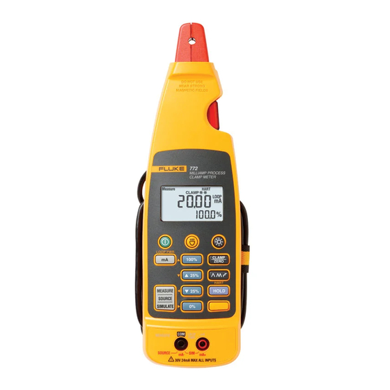
Page 4: Getting Acquainted With The Meter
Getting Acquainted with the Meter Figures 1-4 explain the Meter’s features, buttons, input/output jacks, and display. LOOP PWR mA SCALE mA IN/OUT HART Fjv06.eps Number Description Turns the Meter on and off Measurement spotlight LED button Turns the display backlight on and off Switches the Meter to Clamp Measure mode. - Page 5 MILLIAMP PROCESS CLAMP METER Fjv05.eps Number Description Detachable clamp Tactile Barrier docked and un-docked. Refer to “Safety Information and Symbols”. Display Measurement spotlight LED Figure 2. The Milliamp Process Clamp Meter...
- Page 6 Fjv07.eps Number Description Main display values HOLD is activated Clamp is active Test lead jack indicator. Test lead connection is required. HART 250 resistor is engaged Shift is active Reading is scaled Loop Power is active Milliamps Volts dc Percentage Secondary display Ramping is engaged Low battery symbol...
-
Page 7: Zero Adjust
Fjv04.eps Number Description Voltage measurement test lead input, also used for voltage sourcing HI. Common test lead input, also used for voltage sourcing LO. -mA test lead input, also used for mA sourcing. +mA test lead input, also used for mA sourcing. Common test lead input. -
Page 8: User Options
To exit ramping, press any button. Probe Holder The Meter is equipped with a probe holder that can either hold a test probe or can be used to attach the Fluke ToolPak. See Figure 5. Fjv08.eps Figure 5. The Probe Holder... -
Page 9: Taking Measurements
Taking Measurements XW Warning To avoid electric shock, do not use the clamp on non- insulated conductors. Measurements can be taken with the clamp in the docked position, remotely using the 1 m cable, or via test leads. For accurate measurements: Always zero the Meter prior to taking measurements with the clamp. - Page 10 To use the test leads for measurements: Insert the test leads into the proper input jacks. See Figure 7. Press the correct button for the measurement. Apply the test leads. Observe the reading on the main display. In mA mode, the secondary display shows the reading in percentage of span.
- Page 11 To enter mA Source mode for the 773, see Figure 8: Insert the test leads into the desired input jacks. Press L. Press until Source appears on the display. Fjv10.eps Figure 8. Sourcing mA Output Simulating mA Output In Simulate mode, the Meter simulates a current loop transmitter. To enter Simulate mode, see Figure 9: Insert the test leads into the mA+ and mA- input jacks.
-
Page 12: Loop Supply
Fjv11.eps Figure 9. Simulating mA Output Loop Supply In Loop Supply mode, the Meter powers a transmitter while measuring the mA signal. To enter Loop Supply mode, see Figure 10: Insert the test leads into the LOOP PWR jacks. See Figure 10. Press N. -
Page 13: Maintenance
Maintenance XW Warning To avoid possible electric shock or personal injury, repairs or servicing not covered in this manual should be performed only by qualified personnel. Cleaning the Meter XW Warning To avoid electrical shock, remove any input signals before cleaning. -
Page 14: Electrical Specifications
Specifications Electrical Specifications Current Measurement With Jaw Ranges ........ 0-20.99 mA; 21-100 mA Resolution......0.01 mA; 0.1 mA Accuracy......0.2 % + 5 counts;1 % + 5 counts In Circuit Range ........0-24 mA Resolution......0.01 mA Accuracy......0.2 % + 2 counts Current Source Range ........ -
Page 15: Environmental Specifications
Environmental Specifications Operating Temperature ..... -10 ~50 C Storage Temperature....-25 ~60 C Operating Humidity ....<90 % RH @ <30 C ;<75 % RH @ 30 ~50 C Operating Altitude ...... 0 ~ 2000 m IP Rating........IP 40 Vibration Requirements ..... -
Page 16: User Replaceable Parts
LIMITED WARRANTY & LIMITATION OF LIABILITY This Fluke product will be free from defects in material and workmanship for 3 years (one year for cable and clamp) from the date of purchase. This warranty does not cover fuses, disposable batteries or damage from accident, neglect, misuse or abnormal conditions of operation or handling.
Need help?
Do you have a question about the 772 and is the answer not in the manual?
Questions and answers