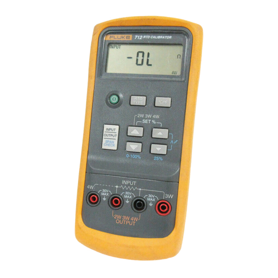
Fluke 712 Calibration Manual
71x series
process calibrators
Hide thumbs
Also See for 712:
- Instruction manual (17 pages) ,
- Instruction sheet (17 pages) ,
- Specifications (1 page)


Need help?
Do you have a question about the 712 and is the answer not in the manual?
Questions and answers