Exmark LAZER Z XS Operator's Manual
Air-cooled models
Hide thumbs
Also See for LAZER Z XS:
- Operator's manual (60 pages) ,
- Parts manual (32 pages) ,
- Setup instructions (5 pages)

Related Manuals for Exmark LAZER Z XS


Summary of Contents for Exmark LAZER Z XS
- Page 1 LAZER Z ® AIR-COOLED MODELS For Serial Nos. 850,000 & Higher Part No. 4500-551 Rev. A...
- Page 2 Replacements may be ordered through the engine manufacturer. Exmark reserves the right to make changes or add improvements to its products at any time without incurring any obligation to make such changes to products manufactured previously.
-
Page 3: Introduction
All Exmark parts are thoroughly tested and inspected before leaving the factory, however, attention is required on your part if you are to obtain the fullest measure of satisfaction and performance. -
Page 4: Table Of Contents
Contents Pump Drive Belt Tension....... 37 Mule Drive Belt Tension Adjustment ..... 37 Deck Belt Tension ........38 Introduction ............3 Belt Guide Adjustment ........38 Safety ..............5 Brake Link Adjustment........39 Safety Alert Symbol ......... 5 Brake Adjustment.......... 39 Safe Operating Practices ........ -
Page 5: Safety
Only use accessories and DANGER: White lettering / Red background. attachments approved by Exmark. Indicates an imminently hazardous situation which, if • Wear appropriate clothing including safety glasses, not avoided, Will result in death or serious injury. - Page 6 Safety DANGER DANGER In certain conditions gasoline is extremely In certain conditions during fueling, static flammable and vapors are explosive. electricity can be released causing a spark which can ignite gasoline vapors. A fire or A fire or explosion from gasoline can burn explosion from gasoline can burn you and you, others, and cause property damage.
- Page 7 Safety Operation damage and make repairs before restarting and operating the mower). WARNING – Before clearing blockages. – Whenever you leave the mower. Operating engine parts, especially the muffler, become extremely hot. Severe burns • Stop engine, wait for all moving parts to stop, and can occur on contact and debris, such as engage parking brake: leaves, grass, brush, etc.
- Page 8 Safety • Remove or mark obstacles such as rocks, tree DANGER limbs, etc. from the mowing area. Tall grass can hide obstacles. Operating on wet grass or steep slopes can cause sliding and loss of control. Wheels • Watch for ditches, holes, rocks, dips and rises that dropping over edges, ditches, steep banks, or change the operating angle, as rough terrain could water can cause rollovers, which may result...
-
Page 9: Maintenance And Storage
Safety driving under any objects and Do Not contact DANGER them. Charging or jump starting the battery may • In the event of a rollover, take the unit to an produce explosive gases. Battery gases can Authorized Service Dealer to have the ROPS explode causing serious injury. - Page 10 Failure to use original Exmark parts could cause serious injury or death. Replace all parts including, but not limited to, tires, belts, and blades with original Exmark parts.
-
Page 11: Safety And Instructional Decals
Exmark equipment dealer or labels. distributor or from Exmark Mfg. Co. Inc. • Replace all worn, damaged, or missing safety • Safety signs may be affixed by peeling off the signs. - Page 12 Safety 103-6700 103-1798 103-7218 103-2076 103-7616 103-4930 103-5881...
- Page 13 Safety 109-0872 109-1214 107-2102 109-1215 107-2112...
- Page 14 Safety 116-0127 116-0165 For Style B Slotted Nuts — See “Wheel Hub – Slotted Nut Torque Specification” in the Maintenance section 109-1399 116-0404 109-2219 109-3148 116-0997 116-2643 For Style A Slotted Nuts — See “Wheel Hub – Slotted Nut Torque Specification” in the Maintenance section...
- Page 15 Safety 117–2718 107-9866 1. Fast 3. Neutral 4. Reverse 2. Slow...
-
Page 16: Specifications
Specifications Specifications Model Numbers Serial Nos: 850,000 and Higher LXS35BV605; LXS35BV665; LXS35BV725 Systems Operator Controls • Steering and Motion Control: Engine Note: Motion control levers are adjustable to • Engine Specifications: See your Engine Owner’s two heights. Manual – Separate levers, on each side of the console, •... -
Page 17: Dimensions
• Deck Drive: tapered shafts. – Electric clutch mounted on horizontal engine • Hydraulic Oil Type: Exmark Premium Hydro oil. shaft. “B” Section belt (with self-tensioning idler) from electric clutch to transfer shaft • Hydraulic Oil Capacity: 5.5 qt. (5.2 L) mounted on deck. -
Page 18: Torque Requirements
Specifications Overall Length: Bolt Location Torque Anti-Scalp Roller Nyloc 30-35 ft-lb (41-47 N-m) 60 inch 66 inch 72 inch Nut See Figure 10 Deck Deck Deck Anti-Scalp Roller Hex 50-55 ft-lb (68-75 N-m) Roll Bar - 81.9 inches 83.4 inches 85.8 inches Capscrew See Figure 10 (208.0 cm) -
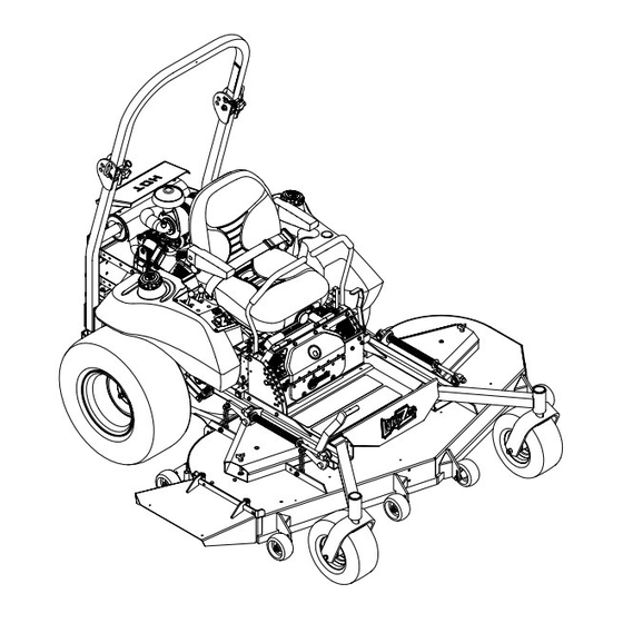
Page 19: Product Overview
Operation Product Overview Operation Note: Determine the left and right sides of the machine from the normal operating position. Controls Motion Control Levers The motion control levers located on each side of the console control the forward and reverse motion of the machine. -
Page 20: Ignition Switch
Operation Push the lever forward and down to disengage the The fuel gauge monitors the amount of fuel in the left brake. tank only. Use the fuel from the right fuel tank first. When the right fuel tank is empty, switch to the left The unit must be tied down and brake engaged when fuel tank. -
Page 21: Pre-Start
Operation Pre-Start Fill fuel tank on level ground. For best results use only clean, fresh regular grade unleaded gasoline with an octane rating of 87 or higher. Important: Never use methanol, gasoline containing methanol, gasohol containing more than 10% ethanol, premium gasoline, or white gas because the fuel system could be damaged. -
Page 22: Stopping The Engine
Operation Stopping the Engine time. If the engine does not start, allow a 60 second cool-down period between starting 1. Bring the unit to a full stop. attempts. Failure to follow these guidelines 2. Disengage the PTO. can burn out the starter motor. 3. -
Page 23: Adjusting The Cutting Height
Operation Figure 6 1. Handles Out (Neutral 5. Neutral Lock) 2. Handles In (Neutral) 6. Reverse 3. Front of Unit 7. Neutral Lock 4. Forward Figure 7 Driving Forward 1. Handles Out (Neutral 4. Forward Lock) 1. Release the parking brake. 2. - Page 24 Operation deck lift assist lever located at the front right 6. Place the rollers in one of the positions shown corner of the floor pan. (Figure 9). Rollers will maintain 3/4 inch (19 mm) clearance to the ground to minimize gouging and Note: When changing the cutting height roller wear or damage.
-
Page 25: Transporting
Operation WARNING Loading a unit on a trailer or truck increases the possibility of backward tip-over. Backward tip-over could cause serious injury or death. • Use extreme caution when operating a unit on a ramp. • Use only a single, full width ramp; Do Not use individual ramps for each side of the unit. - Page 26 Operation Important: Do Not attempt to turn the unit while on the ramp, you may lose control and drive off the side. Avoid sudden acceleration when driving up a ramp and sudden deceleration when backing down a ramp. Both maneuvers can cause the unit to tip backward.
-
Page 27: Maintenance
Maintenance Maintenance Note: Determine the left and right sides of the machine from the normal operating position. WARNING WARNING While maintenance or adjustments are being The engine can become very hot. Touching made, someone could start the engine. a hot engine can cause severe burns. Accidental starting of the engine could Allow the engine to cool completely before seriously injure you or other bystanders. -
Page 28: Periodic Maintenance
Maintenance Maintenance Service Maintenance Procedure Interval • Change the hydraulic filter (Every 250 hours/yearly if using Mobil 1 15W50) • Check the wheel hub slotted nut torque specifications. Every 500 hours • Check the wheel lug nuts. • Replace the air cleaner elements. (May need more often under severe conditions. See the Every 600 hours Engine Owner’s Manual for additional information.) •... - Page 29 Maintenance short lengths to reduce voltage drop between Voltage Percent Maximum Charging systems. Make sure the cables are color coded or Reading Charge Charger Interval labeled for the correct polarity. Settings 12.6 or 100% 16 volts/7 CAUTION Charging greater amps Required Connecting the jumper cables incorrectly 12.4 –...
-
Page 30: Check Mower Blades
Maintenance Figure 12 1. Install bushing in blade prior to installing bushing in spindle. Figure 11 1. Positive (+) cable on discharged battery B. Install bushing/blade assembly into spindle. 2. Positive (+) cable on booster battery 3. Negative (–) cable on the booster battery 4. -
Page 31: Check Safety Interlock System
Note: If machine does not pass any of these tests, do not operate. Contact your authorized EXMARK SERVICE DEALER. Check Safety Interlock Important: It is essential that operator safety... -
Page 32: Change Engine Oil
2. Clean area around hydraulic reservoir cap and remove cap. Oil level should be to the top of the damaged. baffle inside the tank. If not, add oil. Use Exmark 5. Check the condition of the inner element. Replace Premium Hydro oil. Replace hydraulic reservoir whenever it appears dirty, typically every other cap and tighten until snug. -
Page 33: Check Condition Of Belts
Maintenance system, frame, and other components. Foam filling Lubrication Chart tires will void the warranty. Fitting Initial Number of Service Locations Pumps Places Interval Check Condition Of Belts 7. Pump Yearly Service Interval: Every 40 hours Drive Belt Idler Arm 1. -
Page 34: Lubricate Brake Handle Pivot
7. Insert one bearing, one new seal into the wheel. 1. Stop engine, wait for all moving parts to stop, and remove key. Engage parking brake. Note: Seals (Exmark PN 103-0063) must be replaced. 2. Unhook seat latch and tilt seat up. -
Page 35: Change Hydraulic System Filter
Important: Before reinstalling new filter, fill 1. Style A (black finish) 3. Style B (yellow zinc) it with Exmark Premium Hydro oil and apply 2. .03 inch (.76 mm) 4. .24 inch (6 mm) a thin coat of oil on the surface of the rubber seal. -
Page 36: Thread Locking Adhesives
Maintenance 2. Torque the slotted nut to 200 ft-lb (271 N-m). • Sheave retaining bolt in the end of engine crankshaft. 3. Check distance from bottom of slot in nut to inside edge of hole. Two threads (0.1 inch) or •... -
Page 37: Adjustments
Maintenance Adjustments front swivel using locking nut in front of swivel. Repeat for right side. Note: Disengage PTO, shut off engine, wait for 11. Recheck that the 3/4 inch (19 mm) blocks fit just all moving parts to stop, engage parking brake, and snugly under the brackets and that the tension on remove key before servicing, cleaning, or making any all the chains is approximately equal. -
Page 38: Deck Belt Tension
Maintenance side engine deck support, is positioned between the centers of the two alignment holes in the left support plate (Figure 18 and Figure 19). It is necessary to adjust the belt tension when the center of the bolt head is at or below the center of the bottom alignment hole. -
Page 39: Brake Link Adjustment
Maintenance Brake Link Adjustment adjacent nyloc nut. Tighten the jam nut above the trunnion roller. Check to make sure brake is adjusted properly. 4. If the correct gap can no longer be achieved 1. Disengage brake lever (lever down). because there is no clearance between nyloc nut below the spring and the jam nut above 2. -
Page 40: Reverse Indicator Adjustment
Maintenance A. Loosen both brake mounting bolts one-half to one full turn (see Figure 23). Note: Do Not remove the brake pole from the field shell/armature. The brake pole has worn to match the armature and needs to continue to match after the shim is removed to ensure proper brake torque. -
Page 41: Motion Control Linkage Adjustment
Maintenance 5. If adjustment is needed, loosen the nut against the CAUTION yoke and while applying slight rearward pressure on the motion control lever, turn the head of the Raising the mower deck for service or adjustment bolt in the appropriate direction until maintenance relying solely on mechanical lever is centered (keeping rearward pressure on or hydraulic jacks could be dangerous. -
Page 42: Motion Control Damper Adjustment
Maintenance Motion Control Damper Operator does not have to be in the seat because of the jumper wire being used. Run Adjustment engine at full throttle and release brake. 7. The reverse indicator spring must be correct The top damper mounting bolt can be adjusted to before the following adjustments can be made. -
Page 43: Cleaning
Maintenance Cleaning Clean Engine Cooling System Service Interval: Before each use or daily (May be required more often in dry or dirty conditions.) CAUTION Excessive debris around the engine cooling air intake and inside of the pump drive belt compartment and damaged or missing Figure 30 rubber baffles can cause the engine and 1. -
Page 44: Clean Grass Build-Up Under Deck
Maintenance Clean Grass Build-Up Under Federal law states that batteries should not be placed in the garbage. Management and disposal practices Deck must be within relevant federal, state, or local laws. Service Interval: Before each use or daily If a battery is being replaced or if the unit containing the battery is no longer operating and is being 1. -
Page 45: Troubleshooting
Troubleshooting Troubleshooting Important: It is essential that all operator safety mechanisms be connected and in proper operating condition prior to mower use. When a problem occurs, do not overlook the simple causes. For example: starting problems could be caused by an empty fuel tank. The following table lists some of the common causes of trouble. - Page 46 Troubleshooting Problem Possible Cause Corrective Action Engine overheats. 1. Engine load is excessive. 1. Reduce the ground speed. 2. Oil level in the crankcase is low. 2. Add oil to the crankcase. 3. Cooling fins and air passages for the 3.
- Page 47 Troubleshooting Problem Possible Cause Corrective Action Clutch will not engage. 1. Fuse is blown. 1. Replace fuse. Check coil resistance, battery charge, charging system, and wiring connections and replace if necessary. 2. Low voltage supply at the clutch. 2. Check coil resistance, battery charge, charging system, and wiring connections and replace if necessary.
-
Page 48: Schematics
Schematics Schematics Electrical Diagram GREEN PINK VIOLET GREEN BLACK BLACK BLUE GREEN GREEN STRIPE PINK/BLACK GREEN BLUE GREEN BLUE STRIPE GREEN/WHITE WHITE BLACK GREEN BLACK BLACK BLUE BLACK GREEN BROWN GREEN STRIPE ORANGE/BLACK STRIPE GREEN/WHITE YELLOW BROWN BLUE BLUE BLACK VIOLET VIOLET GREY... - Page 49 Schematics...
- Page 50 No Claim of breach of warranty shall be cause for cancellation or rescission of the contract of sale of any Exmark mower. All warranty work must be performed by an authorized Exmark Service Dealer using Exmark approved replacement All implied warranties of merchantability (that the parts.
- Page 51 Notes:...
- Page 52 Notes:...
-
Page 53: Service Record
Service Record Date: Description of Work Done: Service Done By:... - Page 55 Figure 31 This page may be copied for personal use. 1. The maximum slope you can safely operate the machine on is 15 degrees. Use the slope indicator to determine the degree of slope of hills before operating. Do Not operate this machine on a slope greater than 15 degrees. Fold along the appropriate line to match the recommended slope.
- Page 56 SEE EXMARK’S COMPLETE LINE OF ACCESSORIES AND OPTIONS MID-MOUNT RIDING ACCESSORIES AND OPTIONS CUSTOM RIDE SEAT SUSPENSION SYSTEM OPERATOR CONTROLLED DISCHARGE FULL SUSPENSION SEAT ROLL OVER PROTECTION SYSTEM (ROPS) DECK LIFT ASSIST KIT SUN SHADE HITCH KIT TRASH CONTAINER LIGHT KIT...
Need help?
Do you have a question about the LAZER Z XS and is the answer not in the manual?
Questions and answers