Table of Contents
Advertisement
Quick Links
Models
GP8055, GP8060, GP8065
Updated 3/07
Contents:
Installation Instructions:
Pump Specifications:
Exploded View/Parts List:
Repair Kits/Tool List:/Torque Specifications
Troubleshooting Chart:
Repair Instructions:
Dimensions:
Warranty Information
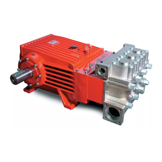
Triplex Ceramic
Plunger Pump
Models Manual
page 2
page 3-5
pages 6-7
page 8
page 8
pages 9-11
back page
back page
Advertisement
Table of Contents

Related Manuals for Giant GP8055


Summary of Contents for Giant GP8055
- Page 1 Triplex Ceramic Models Plunger Pump Models Manual GP8055, GP8060, GP8065 Contents: Installation Instructions: page 2 Pump Specifications: page 3-5 Exploded View/Parts List: pages 6-7 Repair Kits/Tool List:/Torque Specifications page 8 Troubleshooting Chart: page 8 Repair Instructions: pages 9-11 Dimensions: back page Updated 3/07 Warranty Information back page...
-
Page 2: Installation Instructions
INSTALLATION INSTRUCTIONS Installation of the Giant Industries, Inc., pump is not a 5. Crankshaft rotation on Giant Industries, Inc. complicated procedure, but there are some basic steps pumps should be made in the direction designated by common to all pumps. The following information is to be the arrows on the pump crankcase. - Page 3 Specifications Model GP8055 U.S. (Metric) Volume ............. Up to 75.5 GPM ..(285 LPM) Discharge Pressure .......... Up to 3000 PSI ..(200 bar) Speed ............... Up to 580 RPM ..580 RPM Inlet Pressure ........... Up to 29 PSI .... (2.0 bar) Plunger Diameter ..........
- Page 4 Specifications Model GP8060 U.S. (Metric) Volume ............. Up to 90 GPM ..(341 LPM) Discharge Pressure .......... Up to 2500 PSI ..(172 bar) Speed ............... Up to 580 RPM ..580 RPM Inlet Pressure ........... Up to 29 PSI .... (2.0 bar) Plunger Diameter ..........
- Page 5 Specifications Model GP8065 U.S. (Metric) Volume ............Up to 105 GPM ..(400 LPM) Discharge Pressure ......... Up to 2000 PSI ..(140 bar) Speed .............. Up to 580 RPM ..580 RPM Inlet Pressure ..........Up to 29 PSI .... (2.0 bar) Plunger Diameter ..........
- Page 6 Exploded View - GP8050, GP8060, GP8065...
-
Page 7: Table Of Contents
Part List - GP8050, GP8060, GP8065 Item Part Description Item Part Description 05024 Crankcase 05117 Pressure Ring (GP8065) 06912 Oil Filler Plug Assy with Vent 05068 Pressure Ring (GP8060) 05035 Oil Dipstick Assy 05276 Pressure Ring (GP8055) 06225 O-Ring 06997 V Sleeve (GP8065) 07109 Plug G1/2... -
Page 8: Hexagon Nut
GP8055/GP8060/GP8065 PUMP REPAIR KITS Plunger Packing Kits Oil Seal Kit - #09221 GP8055 - #09616 Item Part # Description Qty. Item Part # Description Qty. 05056 O-Ring 13286 O-Ring 05057 Compact Ring 05281 Support Ring 05058 Radial Shaft Seal 05066 O-Ring Inlet Valve Kit - #09587 07723... -
Page 9: Centering Stud
GP8055/GP8060/GP8065 PUMP REPAIR INSTRUCTIONS Valve Inspection and Repair 1) Remove bolts (58). 2) Remove discharge 3) Take out pressure springs casing (50B) up and away. (57A). Pull out assembled valves (51 & 52) with fitting tool. 4) The spring tension cap (51A, 52A) is screwed together with the valve seat (51B or 52B). -
Page 10: Hexagon Screw
GP8055/GP8060/GP8065 PUMP REPAIR INSTRUCTIONS 8) Take out the seal case (38) from the valve (if Be careful not to damage the seal necessary secure 2 screwdrivers in the front O-ring sleeve (39) and pressure ring (41). Check the inner groove to extract seal casing from valve casing). diameter of the pressure ring for wear and if neces- Coat seals with silicon grease before installing. -
Page 11: Cooling Vane Plate
GP8055/GP8060/GP8065 PUMP REPAIR INSTRUCTIONS To Dismantle Crankcase Gear 10) Take out plungers and seal sleeves as described 11) Remove the connecting rod screws (24). above. Drain the oil by taking off the plug (12). After removing the clip ring (33B), lever out the seal retainer Connecting rods are marked 1 to 3 (33) with a screwdriver. -
Page 12: Washer
Liability under this warranty is on all non-wear parts and limited to the replacement or repair of those products returned freight prepaid to Giant Industries which are deemed to be defective due to workmanship or failure of material. A Returned Goods Authorization (R.G.A.) number and completed warranty evaluation form is required prior to the return to Giant Industries of all products under warranty consideration.