LG LSC27990TT Service Manual
Sxs refrigerator
Hide thumbs
Also See for LSC27990TT:
- User manual (191 pages) ,
- Service manual (106 pages) ,
- Specifications (2 pages)
Table of Contents
Advertisement
Quick Links
Download this manual
See also:
User Manual
Advertisement
Table of Contents
Troubleshooting

Related Manuals for LG LSC27990TT


Summary of Contents for LG LSC27990TT
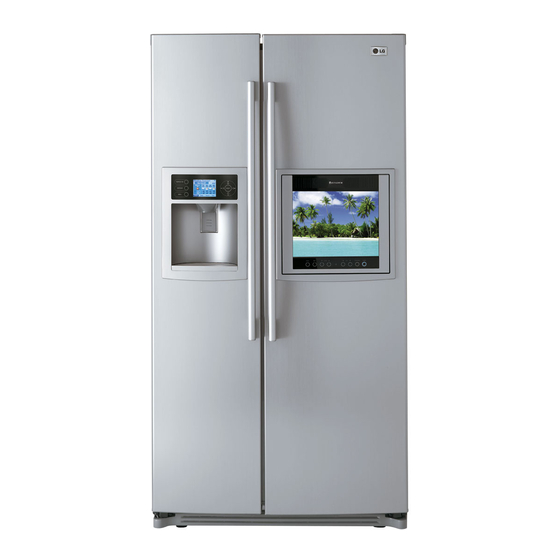
- Page 1 http://aic.lgservice.com REFRIGERATOR SERVICE MANUAL CAUTION PLEASEREAD CAREFULLY THE SAFETY PRECAUTIONSOF THIS MANUAL BEFORE CHECKING OR OPERATINGTHE REFRIGERATOR. MODEL : LSC27990TT COLOR : TITANIUM...
-
Page 2: Table Of Contents
CONTENTS WARNINGS AND PRECAUTIONS FOR SAFETY ........................ SPECIFICATIONS ................................... PARTS IDENTIFICATION ................................ HOW TO INSTALL THE REFRIGERATOR ..........................HOW TO ADJUST DOOR HEIGHT ............................FILTER ....................................HOW TO CONTROL THE ICEMAKER WATER SUPPLY ....................MICOM FUNCTION ................................EXPLANATION OF MICOM CIRCUIT ........................... EXPLANATION OF PWB CIRCUIT ............................. -
Page 3: Warnings And Precautions For Safety
WARNINGS AND PRECAUTIONS FOR SAFETY Please observe the following safety precautions to use the 8. Do not fray, damage, run over, kink, bend, pull out, or refrigerator safely and correctly and to prevent accident or twist the power cord. injury when servicing. 9. -
Page 4: Specifications
SPECIFICATIONS 1. Ref No. : GR-G277STSA(LSC27990TT) ITEMS SPECIFICATIONS ITEMS SPECIFICATIONS DIMENSIONS 908 x 896 x 1771 mm DRIER MOLECULAR SIEVE XH-7 WxDxH CAPILLARY TUBE ID a0.83 (3511/16x355h6x69W16 i n.) NET WEIGHT FIRST DEFROST 4 - 5 Hours 145 kg (319.7 Ibs.) COOLING SYSTEM DEFROST CYCLE 13 - 15 Hours... -
Page 5: Parts Identification
PARTS IDENTIFICATION 1. Ref No. : GR-G277STSA(LSC27990TT) PWB Cover \\\,_ Water Tubes Frame Display Ice & Dispenser Button ..... '}i!l]J!iili _ === Freezer Refrigerator Compartment Compartment Dairy Product Corner Water Filter Automatic Lamp Icemaker Shelf Shelf Lamp Snack Drawer Shelf Door Rack Drawer Lamp... -
Page 6: How To Install The Refrigerator
HOW TO INSTALL REFRIGERATOR 1. How to Adjust Door Height of Refrigerator • Make the refrigerator level first. (If the refrigerator is not installed on a flat floor, the height of freezer and refrigerator door may not be the same.) 1) If the freezer door is lower than the refrigerator 2) If the freezer door is higher than the refrigerator door:... -
Page 7: Filter
NOTE: - To purchase replacement water filter cartridges, visit your local appliance dealer or part distributor. - You can also visit our website : www.lgappliances.com or call 1-877-714-7481. LG MDL PART NO MAKER NOTE: There will be some water (25cc) in the filter GR-G277STSA... -
Page 8: How To Control The Icemaker Water Supply
HOW TO INSTALL REFRIGERATOR 3. How to Control the Amount of Water Supplied to Icemaker. 3-1. Confirm the amount of water supplied to the icemaker. 1) Confirm the amount of water supplied to the icemaker (1) Press the button (Figure 1) to selsct the level of water (Optimum level --* Large -=, Small.) 2) Icemaker Operation Test (Test mode) -
Page 9: Micom Function
MICOM FUNCTION 1. Monitor Panel 1-1. G R-G277STSA(LSC27990TT) Calendar & Temperature Adjust Button - ' I' oe OSe,ect,oo u, ooJ Lock Button Door Alarm Button Dispenser Selection Button Dispenser Light Button... - Page 10 MICOM FUNCTION 1-2. Display Second Function LCD Check Mode Demo Mode Door Alarm Buzzer Communication Data Check Mode Mute Mode 1. Door Alarm Buzzer Mute Mode Press _))) _ button to the buzzer on or off. 2. Demo Mode Demo mode is available for displaying the refrigerator in a sales setting or similar condition. It allows the display, dispenser, lights, and fan to operate without running the compressor.
- Page 11 MICOM FUNCTION 2. Description of Function 2-1-1. Function of Temperature Selection Division Power Initially On 1st Press 2st Press 3th Press 4th Press Setting Temperature Temperature COLD COLDER COLDEST COOL COOLER Control Freezer Control -2 °F -5 °F -8 °F 7 °F 1 °F Refrigeration...
- Page 12 MICOM FUNCTION 2-1-3. Lock function 1. If desiring to lock the dislay the dispenser and control panel, push on _ _ button more than 3 seconds. Lock icon is appeared at the right of display with lock status. 2. The buzzer sound and control panel and dispenser function is not performed even if pressing display button other than lock key in the lock status.
- Page 13 MICOM FUNCTION 2-2. Dispenser use selection You can select water or ice. =_: Select WATER, CRUSHED ICE, or CUBED ICE by pressing the DISPENSER button as you desire. =_: U se your cup to press lightly on the actuator. • Each graphic is indicated for the selected function. •...
- Page 14 MICOM FUNCTION 2-5. ICE PLUS freezing 1. ICE PLUS freezing is a function to increase the cooling speed of the freezer compartment by running both the compressor and the fan simultaneously. 2. ICE PLUS is cancelled and the refrigerator returns to its default setting in the event of a power interruption. 3.
- Page 15 MICOM FUNCTION 2-7. Control of variable type freezing 1. To increase cooling speed and response to load, the MICOM will vary the speed of the freezer fan between low and high. 2. The MICOM runs the fan at high speed only at power-up and for ICE PLUS cycles, and runs at low speed for all other settings.
- Page 16 MICOM FUNCTION 2-11. Ringing of manual operation, manual frost defrost buzzer 1. The buzzer sounds briefly when the test button on the main PCB is pressed. 2. If you select manual operation, the buzzer sounds three times for 2/lOsecond each, then it sounds three times for 2/10 second each every thirty seconds until the door is closed.
- Page 17 MICOM FUNCTION 2-14. Sequential operation of components Component products such as compressor, frost removal heater, freezing room fan, cooling fan, and step motor damper are sequentially operated as follows for preventing noise and part damage occurred due to simultaneous operation of many parts in applying initial power and completing test.
- Page 18 MICOM FUNCTION 2-15. Failure Diagnosis Function 1. Failure diagnosis facilitates service when a failure code shows during product operation. 2. When a failure is detected, the buttons are deactivated. 3. If a failure code is released, the MICOM resets and normal operation continues. 4.
- Page 19 MICOM FUNCTION ALL DISPLAYPARTSTURN OFF OTHERTHAN FREEZER ROOMNOTCH TEMPERATUREDISPLAYAND REFRIGERATORROOM NOTCH TEMPERATUREDISPLAY(FAILURECODE INDICATIONPART) IN CASEOF INDICATINGFAILURE MODES(EXCEPT FORNOTE1, NOTE2) NOTE1 ) FREEZER ROOM NOTCHTEMPERATUREDISPLAY AND REFRIGERATORROOMNOTCH TEMPERATUREDISPLAY(FAILURECODE INDICATIONPART)ARE NORMALLY INDICATED INABNORMAL AMBIENT SENSOR, AND "Er" INDICATED ON THE AMBIENT TEMPERATUREDISPLAY(EXCEPTFORTHE AMBIENT TEMPERATUREDISPLAY,OTHERDISPLAY PARTSARE INDICATED NORMALLY) NOTE 2) R2-SENSOR, WATER-TANK SENSOR AND OPTICHILL SENSOR IS NOT INDICATED ON THE FAILURE INDICATING PART BUT INDICATED IN CHECKING ALL DISPLAY PARTS (WHEN PRESSING THE TEMPERATRUE BUTTON IN THE LOCK STATUS FOR MORE THAN 1 SECOND).
- Page 20 MICOM FUNCTION 2-16. Test Function 1. The test function assists in diagnosing the PWB and determining the exact mode of failure. 2. The test button is on the main PCB. When test mode is engaged, it will complete its test cycle and default to normal operation within 2 hours.
- Page 21 MICOM FUNCTION 2-17. Dispenser Function 1. The dispenser allows serving ice and water without opening the door. 2. Pressing the dispenser switch dispenses crushed or cubed ice or water. If ice is selected, the switch operates the door solenoid also. The door will close 5 seconds after the ice is dispensed. 3.
-
Page 22: Explanation Of Micom Circuit
EXPLANATION FOR MICOM CIRCUIT 1. Explanation for PWB circuit 1-1. Power circuit The power circuit includes a Switched Mode Power Supply (SMPS). It consists of a rectifier (BD1 and CE1) converting AC to DC, a switch (IC2) switching the DC voltage, a transformer, and a feedback circuit (IC3 and IC4). Caution : Since high voltage (160 Vdc) is maintained at the power terminal, wait at least 3 minutes after unplugging the appliance to check the voltages to allow the current to dissipate. - Page 23 EXPLANATION FOR MICOM CIRCUIT 1-2. Oscillation circuit The oscillation circuit generates a basic clock signal for synchronization and time calculation related to the transmission of data and calculations made by the M ICOM (IC 1). The oscillator (OSC1) must always be replaced with an exact replacement part.
- Page 24 EXPLANATION FOR MICOM CIRCUIT 1-4. Load/dispenser operation, door opening circuit 1. LOAD DRIVING CIRCUIT =_The fan operates at the regular speed even if the door of the refrigerator or freezer is opened. When the doors are closed, the fan reverts to its original speed. =_(A), (B), (C), and (D) of door switch for the freezer or refrigerator are connected to the door open sensing circuit in parallel toward both ends of switch to determine door open at MICOM.
- Page 25 EXPLANATION FOR MICOM CIRCUIT 1-5. Dispenser operation circuit (1) GR-G277STSA(LSC27990TT) R¥7 EALEI_I21 KID 5003_ IALEJEI_I21 ALOI_2 IWlO ALOI_2 RYIO _DI_2 < £N ---_ ..-_-Y4 ....1_007 FN414B 1) Check load driving status WATER VALVE PILOT GEARED SOLENOID SOLENOID Type of Load MOTOR CUBE DISPENSER...
- Page 26 EXPLANATION FOR MICOM CIRCUIT 1-6. Door opening sensing circuit (1) GR-G277STSA(LSC27990TT) (MICOM) CCZI* R_030R S/_ ..Measuring part ......ICl (MICOM) No. (44, 45) / (45, 46) / (47, 48) Pin Door of Freezer and Refrigerator Closing 5 V ((_)- (_, (_- Switch at both ends are at Off status) Opening 0 V ((_) - (_, (_)- (_).
- Page 27 EXPLANATION FOR MICOM CIRCUIT 1-7. Temperature sensing circuit (1) GR-G277STSA(LSC27990TT) F-SENSOR IAI_] D-SENSOR C05, i RI-SENSOR IAINZ} R2-SENSOR CC23']_ _AIN3J IAIN4_ MA_/OPTI - FF_SH ccea,_ /50V The circuits involving the freezer and refrigerator sensors control the temperature in both the freezer and the refrigerator. The icemaker sensor detects when ice is made.
- Page 28 EXPLANATION FOR MICOM CIRCUIT 1-8. Switch entry circuit The following circuits are sensing signal form the damper motor reed switch for testing and diagnosing the refrigerator. (1) G R-G277STSA(LSC27990TT) 4=7K o 5Wlo (MIC©M) _k CCIO* _223 1-9. Option designation circuit (model separation function) (1) G R-G277STSA(LSC27990TT) 4o7K_ The circuits shown above vary according to which features are included on your particular model.
- Page 29 EXPLANATION FOR MICOM CIRCUIT 1-10. Stepping motor operation circuit (1) GR-G277STSA(LSC27990TT) The motor is driven by magnetism formed in the areas of the coils and the stator. Rotation begins when a HIGH signal is ] Jcl0 CON7 TA7774P 9,16 CEI3 (MI00M) /50V ST/OPB...
- Page 30 EXPLANATION FOR MICOM CIRCUIT 1-11. Fan motor driving circuit (freezer, mechanical area) 1. The circuit cuts all power to the fan drive IC, resulting in a standby mode. 2. This circuit changes the speed of the fan motor by varying the DC voltage between 7.5 Vdc and 16 Vdc. 3.
- Page 31 EXPLANATION FOR MICOM CIRCUIT 1-12. Temperature compensation and temperature compensation circuit 1. Temperature compensation in freezer and refrigerator (1) GR-G277STSA(LSC27990TT) TRI7 _>EOK Temperature c ompensation at refrigerator 56 [AINO} _-,R_,F_ - _ _ ternperaturecornpensationatfreezer57 tAINH Freezer Refrigerator Resistance value Temperature Resistance value Temperature Remarks...
- Page 32 EXPLANATION FOR MICOM CIRCUIT I_ Temperature compensation table at the refrigerator is as follows: resistance 470 _-_ 2 kL-_ i 3.3 kL-_ 5.6 k'_ 8.2 kL-_ 10 k'_ 12 kL-_ 18 kL-_ 33 kL-2 56 k_-2 180 k'_2 Current "" -_.[ [resistance ................
- Page 33 EXPLANATION FOR MICOM CIRCUIT 2. Compensation circuit for temperature at freezer (1) G R-G277STSA(LSC27990TT) RE8* Rig* R22. R23_ Temperature compensation in CUT JCR1 +1 °C [+1.8 °F] +2 °C [+3.6 °F] JCR2 +1 °C [+1.8 °F] JCR3 -1 °C [-1.8 °F] -2 °C [-3.6 °F] JCR4 -1 °C [-1.8 °F]...
- Page 34 EXPLANATION FOR MICOM CIRCUIT 1-13. Communication circuit and connection L/Wire between main PCB and display The following communication circuit is used for exchanging information between the main MICOM of the Main PCB and the dedicated MICOM of the LCD Display PCB. A bi-directional lead wire assembly between the two boards is required for the display to function properly.
- Page 35 EXPLANATION FOR MICOM CIRCUIT 2) Sensor resistance characteristics table Refrigerator sensor 1&2 Measuring Temperature (°C) Freezing Sensor Defrost sensor, Ambient sensor -20 °C 22.3 k_-_ 77 k_-:' -15 °C 16.9 k_-_ 60 k_-:' -15 °C 13.0 k_-_ 47.3 k_-:' -5 °C 10.1 k_-_ 38.4 k_-:' 0 °C...
- Page 36 EXPLANATION FOR MICOM CIRCUIT 1-14. OptiFresh stepping MOTOR/Display (1) GR-G277STSA(LSC27990TT) CON8 Rra9 2f_.IKF MA_LC/_M/_TI-F_SH lAIN41 TA7774P 9,16 iCu_6 ISTEPPlNG ] 1(3{ ST/ ° 61 4,5,- 2,13 r_7, ..L]Oi L302 L303 1_'_301 470_1/4W << 014 E KTAIZ_3 L%_ J c,_ 21<...
-
Page 37: Pwb Parts Diagram And List
EXPLANATION FOR MICOM CIRCUIT 2. PWB parts diagram and list 2-1. PWB Assembly, main part diagram (1) G R-G277STSA(LSC27990TT) -37 -... - Page 38 EXPLANATION FOR MICOM CIRCUIT 2-2. Parts list (1) GR-G277STSA(LSC27990TT) - 38 -...
- Page 39 EXPLANATION FOR MICOM CIRCUIT 4a;zo,_3OOT,_ EAT S_ _47 7Z_O304_ - 39 -...
- Page 40 A01010088 32BIT RISC MICROPROCESSOR - SAMSUNG 8302410A20-YO80 A01030086 IC - SO14 741V14D A01040024 PIC - MACROCHIP PIC18F2520 (SO28) - LG J,_2 A01050043 MOSFET SWITCH 813861DV (SSOT6) A01050046 POWER MOSFET - ADV POWER 9930M (SO8) A01060002 TRANSISTOR-PNP - ONSEMI MMBT3906L_1-SOT23...
- Page 41 - AD,U!_:<{I 12mm A18080007 _'_21 SWI[CH _,_@_ - LG 2z_lr-_{o_u_E_ 12mm 1 i_ _,_@_ - LG 2x_ rJ{ O_U_F_ A18080008 _!_'_21 SWI[CH ,',_@_ - LG 2,_lr-_{ o_u_E_ 12mm 5_ z ,',_@_ - LG 2,q c}{ o_u_E A60010026 PROGRAM OS - WIN CE 4.2 CORE IIC...
- Page 42 EXPLANATION FOR MICOM CIRCUIT 2-4. DISPLAY circuit diagram (1) GR-G277STSA(LSC27990TT) ARM920T Instruction Instruction External CACHE Coproc Interface (16KB) JTAG AMBA Processor core • ARMSTDMI (Internal EMbedded ICE) Data WriteBack Data CACHE PA Tag (16KB) <_ BUS CeNT 4" TFT LCD Arbiter/Decode CeNT <C::::::::C>...
-
Page 43: Pwb Circuit Diagram
EXPLANATION FOR MICOM CIRCUIT 3. PWB Circuit Diagram may vary by model. (1) GR-G277STSA(LSC27990TT) p-.. - 43 -... - Page 44 EXPLANATION FOR MICOM CIRCUIT ...... _-s_,_m L]GWT ore, sin _ 2_ _ T_" ..... - 44 -...
-
Page 45: Icemaker Anddispenser Working Principles Andrepair
ICEMAKER ANDDISPENSER WORKING PRINCIPLES ANDREPAIR 1. OPERATION PRINCIPLE 1-1. Operation Principle of Icemaker • Adjusts EJECTOR to Start Position with power on. Icemaking • Waits until water becomes cold after starting the icemaking operation. Harvest • Runs MOTOR to drop ice from the tray into the ICE BIN. (During harvest mode, check if the ice bin is full) •... -
Page 46: Function Of Icemaker
ICEMAKER ANDDISPENSER WORKING PRINCIPLES ANDREPAIR 2. ICEMAKER FUNCTIONS 2-1. Start Position 1. After POWER OFF or power outage, check the EJECTOR's position with MICOM initialization to restart. 2. How to check if it is in place: - Check HIGH/LOW signals from HALL SENSOR in MICOM PIN. 3. - Page 47 ICEMAKER ANDDISPENSER WORKING PRINCIPLES ANDREPAIR 2-5. Function TEST 1. This is a forced operation for TEST, Service, cleaning, etc. It is operated by pressing and holding the Fill Key for 3 seconds. 2. The test works only in the Icemaking Mode. It cannot be entered from the Harvest or Fill mode. (If there is an ERROR, it can only be checked in the TEST mode.) 3.
-
Page 48: Circuit
CIRCUIT (1) G R-G277STSA(LSC27990TT) CIRCUIT DIAGRAM DELUXE - H/BAR PART(H/BAR HEATER,DOOR S/W),CAPACITOR PART, PLUG TYPE, COMPRESSOR EARTH PART, P.T.C ASSEMBLY ON CIRCUIT DIAGRAMS ARE SUBJECTTO CHANGE IN DIFFERENT LOCALITES AND ACCORDANCE WITH MODEL TYPE. • FUSE PARTAPPLiCATiON(OPTiONAL) PWB ASSEMBLY, MAIN - N: NEUTRAL FUSE FUSE PART... -
Page 49: Trouble Diagnosis
TROUBLE DIAGNOSIS 1. Troubleshooting CLAIMS. HOW TO CHECK CAUSES AND CHECK POINTS. 1) No power at outlet. * Measuring instrument: 1. Faulty start Multi tester 2) No power on cord. • Check the voltage. Bad connection between plug and adapter (faulty plug). If the voltage is within +15% _The distance between pins. - Page 50 TROUBLE DIAGNOSIS CLAIMS. CAUSES AND CHECK POINTS. HOW TO CHECK 2. No cooling. 2) Refrigeration system is clogged. • Heat a clogged evaporator to check it.As soon as the Moisture Residual m oisture Air Blowing. Notperformed. cracking sound starts, the clogged.
- Page 51 TROUBLE DIAGNOSIS CLAIMS. CAUSES AND CHECK POINTS. HOW TO CHECK 3. Poor Cooling 1) Refrigerant Partly leaked. • Weldjointleak. Partsleak. 2) Poor defrosting capacity. • Check visually. F Drain path (pipe)clogged. Injectadiabatics intodrain Inectthroughthe i h°se" hole. Sealwithdrain. i Foreignmaterials Adiabatics lumpinput.
- Page 52 TROUBLE DIAGNOSIS CLAIMS. CAUSES AND CHECK POINTS. HOW TO CHECK 3. Poor Cooling Residual Weakheatfrom heater. SheathHeater- rated. frost. Tooshortdefrosting time. Defrost S ensor. - Faultycharacteristics. Seat-D(missing, l ocation, t hickness). Structural f ault. Gasketgap. Air inflowthroughthe fan motor. Badinsulation ofcasedoor. No automaticdefrosting.
- Page 53 TROUBLE DIAGNOSIS CLAIMS. CAUSES AND CHECK POINTS. HOW TO CHECK 3. Poor Cooling 4) No cooling air circulation. Faultyfan motor. Fan is Fanshroudcontact. - Clearance. constrained. Damping evaporatorcontact. Accumulated residual f rost. Fanoverload. - Fan misuse. Small coolingair Insufficient discharge, motorRPM Badlowtermperature RPMcharacteristics.
- Page 54 TROUBLE DIAGNOSIS CLAIMS. CAUSES AND CHECK POINTS. HOW TO CHECK 4. Warm 1) Clogged cooling path. refrigerator Adiabaticsliquid leak?. compartment Foreignmaterials.- Adiabaticsdump liquid temperature. 2) Food storage. Storehotfood. Storetoo muchat once. Dooropen. Packages blockair flow. 5. No automatic 1) Faulty temperature sensor in freezer or refrigerator compartment. •...
- Page 55 TROUBLE DIAGNOSIS CLAIMS. CAUSES AND CHECK POINTS. HOW TO CHECK 6. Condensation 4) Condensation on door. and ice Condensation on the duct door. - Duct door heater is cut. formation. Condensation on the _ RecessHeateriscut. dispense recess. • Ductdoor isopen./ Foreignmaterial c logging. Condensation on the Not fully filled.
- Page 56 TROUBLE DIAGNOSIS CLAIMS. CAUSES AND CHECK POINTS. HOW TO CHECK 7. Sounds 1) Compressor compartment operating sounds. Transformer sound. Badconnection. - -Correct screwconnection. Drip tray vibration sound., Badassembly. Distortion. Foreignmaterialsinside. Back cover machine sound. _ Badconnection. Partlydamaged. Condenser drain sound. Notconnected.
- Page 57 TROUBLE DIAGNOSIS CLAIMS. CAUSES AND CHECK POINTS. HOW TO CHECK 8. Faulty lamp 1) Lamp problem. Filament blows out. (freezer and Glass is broken. refrigerator Not inserted. 2) Bad lamp assembly. compartment). Loosened by vibration. 3) Bad lamp socket. Disconnection. Bad soldering.
- Page 58 TROUBLE DIAGNOSIS CLAIMS. CAUSES AND CHECK POINTS. HOW TO CHECK 10. Structure, 1) Door foam. appearance, Sag. Hingeloose Boltis loosenedduring and others. transportation. Nottightlyfastened. Fastenerwornor damaged. Weakgasket Gasketsealingsurfacedefective. adhesion. Fixedtape. Notproperlyattached. Noise during Hingeinterference. Biggerdoorfoam. operation. Hinge-Pintilted-Poor f latness. Nowasher. No grease.
-
Page 59: Faults
TROUBLE DIAGNOSIS "_ • • ._c .__ "_ ".Z > -a° • "o ° ___>o__ •__ o o_._ i.E _ o rrcc_ • o2_.- o8_o • • • •J €/) •J • _ ._o .a _.:z •J 13.. §oOX • &... - Page 60 TROUBLE DIAGNOSIS .£_ _- __ ._ _._OE_ £ ,_ ..c •_ "_ _>_ 5=oo " o $o o> _o> "_ • 4.,-; "._ "_ ¢ ¢ "N u_ •_ _ _o_o_._ o g°-5 _z_o ° "5 E ,_ 13_ ._ o.
- Page 61 TROUBLE DIAGNOSIS • ,gr2 ° ° >_ > _ _ _ _ __-__ _ _ o cd ,d "6 .,zz • -61 -...
- Page 62 TROUBLE DIAGNOSIS "_ ..C: 13.) .,_J :__° "_3 • • "_ • x: o "-- ¢0 ¢0 • • • ,-: ed • • • - 62 -...
- Page 63 TROUBLE DIAGNOSIS ,_ "_ ,_ o_ "_ CD ..C o0 ._= -_ _e ,_ o .o- _ _.-= do_ _ o0 E _ X_ - -_ -_ o° m _ _- -a _5 "r • _ _-_ > o ,_,, __ ",_ _ •...
- Page 64 TROUBLE DIAGNOSIS "r_ ¢ _..._ o ° "_ ..c: o _ d = =._ =_ _ .=o _ =_ "o_ •- • ..__o_o = -_ -_ _ ._ _ o o_ o3 _ _ _ _ _ _ _ _ _ (,,i •= ¢, rn...
- Page 65 TROUBLE DIAGNOSIS =°_ _-_ o° ,o oo_ _.-_ • • • o o ,° ° _ - "-- _ _0 .,_J ,o .o "o ;ooX "o "_ • o_ "o _d o o°_ • • "o • • • • •_ •...
- Page 66 TROUBLE DIAGNOSIS >, 8 "_ ..c:: o "=. ¢ ¢ ,o8o "_ ¢ > •w "u "_ • "5 "- "- "- "_ ,_'_- .__. _ _ _-_ &_.__ "_5 _ _._ "_ "u "_ _ _ _ _ _ _ .__= _ >...
- Page 67 TROUBLE DIAGNOSIS >_ • "_ o° • "o • "- • oo _- _ _ _ __ o• _ ._ _ • "o o_ _5 • • • • "o oo "-E _o_o ° :E.- • __ _._ _ o= •...
- Page 68 TROUBLE DIAGNOSIS ..-L __ =_ .*=_ • - s _ _ o° =_'_S "- v, "_. _ _ "s _: _ o _ _- o S _ -_ 7" & & _, o "_ "-- • - N =_ N_ _= o o •...
- Page 69 TROUBLE DIAGNOSIS o_ _ ¢ .___ _-_ ¢ EL _. o° L.U o >, N -_._ "-- "_ ¢ ¢ --_ _ __ o co o €- - 69 -...
- Page 70 TROUBLE DIAGNOSIS "N ¢ o • .__ ._ _ _6 o N _'_ oE ,_ d ° =_ o o _° r'r" 13.. ._o (D _:_8 •J _.-_ _-_ ,£2 .gr2 © £ ¢ £ ._ - 70 -...
- Page 71 TROUBLE DIAGNOSIS "5 .c _ .c _ "_ © >, s _2._ _SSoS "_ "5. _.__I_ "U .__ ._ ._o_2 > "_ _ __ _c'_ "-- .gr2 c_ ..._ c_ > "_ "_ 13.. o _ S = © "5 °...
- Page 72 TROUBLE DIAGNOSIS •_ _ ; "_ cc _ "O "_ o >- • _ _a _ ___5 _ _-.__ "-- ,.: _ cd 0 _,_o_=_ cc _ © "_ © "= "a _ .a - "_ .> ..a .> ._> .->...
- Page 73 TROUBLE DIAGNOSIS _ ._ ._ o_._ ,_ < E .c: "_- pr" ¢o ¢o •-- 7£ _ o_ __.__ •_ _ "N "- .__ ._ "_ > > O0 _ "_ "_ _'_ > -73 -...
- Page 74 TROUBLE DIAGNOSIS "5 o• _ ._ _ "_ .__ _ "_ "_ "_ ¢ >- £ '_ 8_ • >- "_ £ ¢ © £ _5 E _ o ._ _ £ £ "_J "52_ > 03 _ £ "-- >, "_ ",_...
- Page 75 TROUBLE DIAGNOSIS >=o P- 0 £ "o >- "- _" >- >- I:1) _ _ _ _ .-_ > £ _=o} £ "_ €/) "_5 g g _ _> ° I::D I::D I::D £ _ _ o._ ._O_o £ - 75 -...
-
Page 76: Cooling Cycle Heavy Repair
TROUBLE DIAGNOSIS 3. Cooling Cycle Heavy Repair 3-1. The Heavy Repair Standards for Refrigerator with R134a Refrigerant Standards Items Unit Purposes Remarks Pipe and piping Min. Pipe: within 1 hour. To protect The opening time should be reduced to a system opening time. - Page 77 TROUBLE DIAGNOSIS 3-2. Summary Of Heavy Repair Process Contents Tools Filter, side cutters - Cut charging pipe ends and discharge refrigerant from drier and compressor. - Use R134a oil and refrigerant for compressor and drier Pipe Cutter, Gas welder, N2 gas - Confirm N2 sealing and packing conditions before use.
- Page 78 TROUBLE DIAGNOSIS 3-3. Precautions During Heavy Repair Items Precautions 1. Use of tools. 1) Use special parts and tools for R134a. 2. Recovery of refrigerant. 1) Continue to recover the refrigerant for more than 5 minutes after turning the refrigerator off. 2) Install a piercing type valve on the high pressure line (drier side).
- Page 79 TROUBLE DIAGNOSIS 3-4. Practical Work For Heavy Repair Items Precautions 1. Removal of residual Evaporator Low pressure side refrigerant. Observe the sequence for removal of refrigerant. (If not, compressor oil may KEY POINT Refrigen_.__.._Helease Condenser leak.) Intake 1) Continue to recover the refrigerant for more than 5 minutes after turning the refrigerator off. 2) Install a piercing type valve on the high pressure line (drier side).
- Page 80 TROUBLE DIAGNOSIS Items Precautions 4. Vacuum degassing. Evaporator Suction pipe Compressor Hot Line Dr_ier pressure T High Blue pressure Yellow - If power is applied KEY POINT during vacuum degassing, vacuum degassing shall be more effective. Pipe Connection - Run the compressor Connect the red hose to the high pressure side and the blue hose to the while charging the low pressure side.
- Page 81 TROUBLE DIAGNOSIS Items Precautions Evaporator Hot Line Compressor --__ Drier Condenser Charging Canister 4) Refrigerant Charging Charge refrigerant while operating a compressor as shown above. 5) Pinch the charging pipe with a pinch-off plier after completion of charging. 6) Braze the end of a pinched charging pipe with copper brazer and test for gas leakage at the brazed parts.
- Page 82 TROUBLE DIAGNOSIS 3-6. Brazing Reference Drawings HOT LINE PIPE ASSEMBLY (Freezer) Copper Brazing Copper Brazing TUBE DRIER ASSEMBLY Copper Brazing Silver Brazing SUCTION PIPEASSEMBLY Copper Brazing JOINTPIPE WlRE CONDENSER ASSEMBLY ASSEMBLY Copper Brazing Silver Brazing Copper Brazing Coppper Brazing - 82 -...
-
Page 83: How To Deal With Claims
TROUBLE DIAGNOSIS 4. HOW TO DEAL WITH CLAIMS 4-1. Sound Problems Checks and Measures Hiss sounds • Explain general principles of sounds. • All refrigerators make noises when they run. The compressor and fan produce sounds. There is a fan in the freezer compartment which blows cool air to freezer and refrigerator compartments. - Page 84 TROUBLE DIAGNOSIS Problems Checks and Measures Sounds of water flowing • Explain the flow of refrigerant. • When the refrigerator stops, the water flowing sound happens. This sound happens when the liquid or vapor refrigerant flows from the evaporator to compressor. Click sounds •...
- Page 85 TROUBLE DIAGNOSIS 4-2. Measures for Symptoms on Temperature Problems Checks and Measures Refrigeration is weak. • Check temperature set in the temperature control knob. • Refrigerator is generally delivered with the button set at normal use (MID). But customer can adjust the temperature set depending on their habit and taste. If you feel the refrigeration is weak, then set the temperature control button at strong...
- Page 86 'www. ambientdevices, conYcat/device/coverage, htmr to know your coverage status. Even if you live in fullcoverage are, your refrigeratorcould not receive wireless weather forecast signal at some place in your home. Unfortunately,LG does not provide you with a service for coverage. - 86 -...
- Page 87 TROUBLE DIAGNOSIS 4-5. Others Problems Checks and Measures The refrigerator case is hot. • Explain the principles of radiator. • The radiator pipes are installed in the refrigerator case and partition plate between the refrigerator and the freezer compartment in order to prevent condensation formation.
-
Page 88: Tv-Radio
TV-RADIO 1. SAFETY PRECAUTIONS 2. FEATURE 1-1. Warning 2-1. Auto Program tuning All stations that can be received are stored. 1. Be sure to make a safety check, if circuit is found, components that appear to have overheated or are otherwise damaged should be replaced with new 2-2. -
Page 89: Controls
TV-RADIO 3. CONTROLS Antenna Jack MENU • OK • CH/PR • • • TV/AV/RADIO POWER TV/AV/RADIO MENU VOLUME Remote Control Sensor POWER - 89 -... -
Page 90: Remote Control Key Functions
TV-RADIO 4. REMOTE CONTROL KEY FUNCTIONS - When using the remote control, aim it at the remote control sensor on the TV. POWER TV/AV/RADIO - ..Selects : TV, AV or Radio "--. MUTE jJJJ Selects MTS sound : Mono, Stereo, Switches the sound on or off. -
Page 91: Troubleshooting
TV-RADIO $5. TROUBLESHOOTING 5-1. General Poor Symptoms Adjustment No Picture 1) No P401, P501 connector 1) Check P1 connector and switched on 2) Poor TV Main PCB 2) Change the TV Main PCB Poor Picture 1) Poor LCD Lamp 1) Change the LCD 2) LCD Connector 2) Check connector and switched on 5-2. -
Page 92: Block Diagram
TV-RADIO 6. BLOCK DIAGRAM < _-- O,J << _J_J -92 -... -
Page 93: Tv Part Disassemble
TV-RADIO 7. TV PART DISASSEMBLE Place tape on the outer edge of the TV case to protect the soft plastic from damage (2 or 3 layers is Using a flat bladed screwdriver, carefully pry the trim loose from the frame. recommended). -
Page 94: How To Disassemble And Assemble
HOW TO DISASSEMBLE AND ASSEMBLE 1. DOOR (3) Disconnect upper hinge (_) from the hinge supporter (_) by grasping the front part of upper hinge and lifting up (Hinge Assembly, U) in arrow direction _A_ and pull 1) Remove lower cover and then disconnect water forward in arrow _ direction. -
Page 95: Handle
HOW TO DISASSEMBLE AND ASSEMBLE 2. HANDLE 3. FAN SHROUD GRILLE 1) Remove the caps and remove the two screws holding 1) Aluminum short handle Model the upper fan grille. (1) Grasp the handle by beth hands and held it upward. 2) Remove the upper fan grille by pressing in the hooks with a screwdriver blade. -
Page 96: Water Valve Disassembly Method
HOW TO DISASSEMBLE AND ASSEMBLE 4. WATER VALVE DISASSEMBLY 4). Separate the Mechanical Cover and Valve Screw. METHOD Mechanical Cove 1) Turn off the power of the refrigerator (pull out the plug). Open the FREEZER and REFRIGERATOR Door and disassemble the Lower Cover. 5) Separate the housing and pull out the valve. -
Page 97: Dispenser
HOW TO DISASSEMBLE AND ASSEMBLE 6. DISPENSER 4) Loosen four screws with a phillips screwdriver and pull the funnel assembly to disconnect. 1) Disconnect funnel and button assembly by pulling down and forward. Funnel Assembly j/L . Funnel Assembly Button 5) The duct cap assembly can be disconnected if the hold lever connecting screw is loosened with a phillips driver. - Page 98 HOW TO DISASSEMBLE AND ASSEMBLE 7) Dispenser Related Parts FRAMEASSEMBLY, DISPLAY 2 I COVER, DISPENSER 3 I DECO, FRAME DISPLAY 4 I PWB(PCB) ASSEMBLY, DISPLAY I FUNNEL ASSEMBLY 8 I MICRO SWITCH 9 I FRAME, FUNNEL 10 I LEVER(SWITCH) 11 I FUNNEL 121 BUTTON LEVER 131 HOLLDER BUTTON 14 I SOLENOID ASSEMBLY...
-
Page 99: Exploded View
EXPLODED VIEW FREEZER DOOR PART: GR-G277STSA(LSC27990TT) : Optional part - 99 -... - Page 100 EXPLODED VIEW REFRIGERATOR DOOR PART: GR-G277STSA(LSC27990TT) : Optional part - 100 -...
- Page 101 EXPLODED VIEW REFRIGERATOR COMPARTMENT: GR-G277STSA(LSC27990TT) 9€ : Optional part - 101 -...
- Page 102 EXPLODED VIEW REFRIGERATOR COMPARTMENT: GR-G277STSA(LSC27990TT) : Optional part (152A) - 102 -...
- Page 103 EXPLODED VIEW MACHINE COMPARTMENT: GR-G277STSA(LSC27990TT) : Optional part 104A - 103 -...
- Page 104 EXPLODED VIEW DISPENSER PART: GR-G277STSA(LSC27990TT) : Optional part - 104-...
- Page 105 EXPLODED VIEW TV PART: GR-G277STSA(LSC27990TT) Analog - 105-...
-
Page 106: Replace Parts List
LG Electr@n_¢s in€° P/No. 3828JD8985A JAN., 2006 Printed in Korea...
Need help?
Do you have a question about the LSC27990TT and is the answer not in the manual?
Questions and answers