Table of Contents
Advertisement
Quick Links
Extron Electronics, USA
Extron Electronics, Europe
1230 South Lewis Street
Beeldschermweg 6C
Anaheim, CA 92805
3821 AH Amersfoort, The Netherlands
800.633.9876 714.491.1500
+800.3987.6673 +31.33.453.4040
FAX 714.491.1517
FAX +31.33.453.4050
www.extron.com
© 2007 Extron Electronics. All rights reserved.
Extron Electronics, Asia
Extron Electronics, Japan
135 Joo Seng Rd. #04-01
Kyodo Building, 16 Ichibancho
PM Industrial Bldg., Singapore 368363
Chiyoda-ku, Tokyo 102-0082
+800.7339.8766 +65.6383.4400
Japan
FAX +65.6383.4664
+81.3.3511.7655 FAX +81.3.3511.7656
User's Manual
High Resolution Fiber Optic Transmitter/Distribution Amplifi er
FOX 500 DA6
68-1363-01 Rev. A
11 07
Advertisement
Table of Contents

Related Manuals for Extron electronics FOX 500 DA6


Summary of Contents for Extron electronics FOX 500 DA6
- Page 1 FAX +65.6383.4664 www.extron.com © 2007 Extron Electronics. All rights reserved. User’s Manual High Resolution Fiber Optic Transmitter/Distribution Amplifi er Extron Electronics, Japan Kyodo Building, 16 Ichibancho Chiyoda-ku, Tokyo 102-0082 Japan +81.3.3511.7655 FAX +81.3.3511.7656 FOX 500 DA6 68-1363-01 Rev. A 11 07...
- Page 2 Precautions Safety Instructions • English Warning Power sources • This equipment should be operated only from the power source This symbol is intended to alert the user of important indicated on the product. This equipment is intended to be used with a main power operating and maintenance (servicing) instructions in system with a grounded (neutral) conductor.
-
Page 3: Fcc Class A Notice
安全须知 • 中文 这个符号提示用户该设备用户手册中 有重要的操作和维护说明。 这个符号警告用户该设备机壳内有暴 露的危险电压,有触电危险。 注意 阅读说明书 • 用 户 使 用 该 设 备 前 必 须 阅 读 并 理 解 所 有 安 全 和 使 用 说 明 。 保存说明书 • 用户应保存安全说明书以备将来使 用。 遵守警告 • 用户应遵守产品和用户指南上的所有安 全和操作说明。... - Page 4 Quick Start Guide — FOX 500 DA6 Install, connect, and operate the FOX 500 DA6 as follows: Step 1 Turn all of the equipment off or disconnect it from the power source. If desired, mount the DA in a rack or furniture, or place it on a desktop.
-
Page 5: Table Of Contents
Quick Start Guide — FOX 500 DA6 cont’d Step 7 For remote monitoring of the status of the Optical 2 link from the master receiver, connect a locally constructed or obtained device to the two Alarm poles of the DA's RS-232/ Alarm 5-pole captive screw connector. - Page 6 Firmware upgrade... 3-23 Appendix A • Reference Information Specifications ...A-2 Part Numbers ...A-6 FOX 500 DA6 part numbers..A-6 Included parts ...A-6 Compatible equipment..A-6 Optional accessory..A-7 Cables ...A-7 All trademarks mentioned in this manual are the properties of their respective owners. FOX 500 DA6 • Table of Contents .
-
Page 7: About This Manual
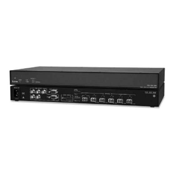
FOX 500 distribution amplifier. They are identified where appropriate, but not specifically described in this manual. About the FOX 500 DA6 The Extron FOX 500 DA6 (figure 1-1) product family consists of two models of ultra-high performance RGB video, audio, and RS-232 serial communications fiber optic distribution amplifiers. The DA inputs VGA - UXGA RGB video, audio, and one-way (DA-to-receiver) RS-232 communications (for applications such as projector control);... -
Page 8: Features
Video input — The DA inputs RGBHV, RGBS, RGsB, or RsGsBs on BNC connectors or a 15-pin HD connector. Six active and individually isolated outputs — The FOX 500 DA6 uses active signal splitting to maintain equal transmiter power to all outputs, maximizing distance capabilities by ensuring full availablility of optical loss budget for each output. -
Page 9: Installation And Operation
Introduction, cont’d FOX 500 DA6 Chapter Two Installation and Operation Mounting.the.Unit Connections Front.Panel.Indicators System.Operation FOX 500 DA6 • Introduction... -
Page 10: Mounting The Unit
Rack mounting UL requirements The following Underwriters Laboratories (UL) requirements pertain to the installation of the FOX 500 DA6 into a rack (figure 2-1). Elevated operating ambient — If installed in a closed or multi-unit rack assembly, the operating ambient temperature of the rack environment may be greater than room ambient. -
Page 11: Connections
15-pin HD female connector. Buffered Loop-through RGsB, connector — If desired, RsGsBs connect a local monitor to this 15-pin HD connector. FOX 500 DA6 • Installation and Operation RS-232 OVER FIBER Tx Rx AUDIO INPUTS REMOTE ALARM RS-232... -
Page 12: N Optical 2 Is Functional Only For Output
1 2* 1 2* 1 2* 1 2* NOT USED NOT USED NOT USED NOT USED Figure 2-5 — DA’s connectors, right side FOX 500 DA6 • Installation and Operation RS-232 OVER FIBER Tx Rx on the REMOTE ALARM RS-232 Tx Rx... -
Page 13: Rear Panel Serial Ports Connection
Front panel Configuration port CONFIG LINK 1 AUDIO LINK 2 (OPTIONAL) Figure 2-8 — FOX 500 DA6 front panel This port is for remote control of the DA or the receiver(s), not for the over fiber RS-232 link. Configuration port — This 2.5 mm mini stereo jack serves the same serial communications function as the rear panel Remote RS-232 port, but is easier to access than the rear port after the unit has been installed and cabled. -
Page 14: Front Panel Indicators
• 1 stop bit • no flow control The maximum distances from the DA or receiver to the controlling device can vary up to 200' (61 m). Factors such as cable gauge, baud rates, environment, and output levels (from the unit and the controlling device) all affect transmission distance. Distances of about 50' (15 m) are typically not a problem. In some cases, the unit may be capable of serial communications via RS-232 up to 250' (76 m) away. FOX 500 DA6 • Installation and Operation 2-10 Ring Sleeve (Gnd) TRS Plug Ring Sleeve • 8 data bits Front Panel Indicators CONFIG LINK 1... -
Page 15: Remote Control
DA, the receiver(s), and the display(s) have power applied. • Ensure that the signal monitoring LEDs (item page 2-11) are indicating correctly for your system configuration. If problems persist, call the Extron S3 Sales & Technical Support Hotline. FOX 500 DA6 • Installation and Operation 2-12 FOX 500 DA6 Chapter Three Remote Control Rear.Panel.Remote.RS-232.Ports Front.Panel.Configuration.Port Simple.Instruction.Set.Control Windows -Based.Program.Control... -
Page 16: Front Panel Configuration Port
Tx Rx Signal ground Do not tin the wires! Bidirectional Ground ( Receive (Rx) Transmit (Tx) Figure 3-1 — Remote connector pin assignments FOX 500 DA6 • Remote Control • 8 data bits Controlling Device Ground ( Receive (Rx) Transmit (Tx) -
Page 17: Unit-Initiated Messages
The unit-initiated messages are listed below: (c) COPYRIGHT 2007, EXTRON ELECTRONICS FOX 500 DA6, Vx.xx, 60-863-xx]] The connected unit issues the copyright message (above) when it first powers on. -
Page 18: Error Responses
The unit sends the Img message (with no variable) whenever the auto image function has been triggered from the master receiver's front panel. FOX 500 DA6 • Remote Control variable) whenever X1$] The unit sends the Tst message whenever a test pattern has been selected or test patterns are turned off from the master receiver's front panel. - Page 19 Remote Control, cont’d FOX 500 DA6 • Remote Control FOX 500 DA6 • Remote Control...
- Page 20 Remote Control, cont’d FOX 500 DA6 • Remote Control 3-10 FOX 500 DA6 • Remote Control 3-11...
- Page 21 Remote Control, cont’d FOX 500 DA6 • Remote Control 3-12 FOX 500 DA6 • Remote Control 3-13...
- Page 22 Remote Control, cont’d FOX 500 DA6 • Remote Control 3-14 FOX 500 DA6 • Remote Control 3-15...
-
Page 23: Windows ® -Based Program Control
> Programs > Extron Electronics > FOX 500 > FOX 500 Control Pgm. The Communication Setup window appears (figure 3-3). Figure 3-3 — Communication Setup window FOX 500 DA6 • Remote Control 3-16 Check for FOX 500 updates FOX 500 Help Select the Com port to which your DA or receiver is connected. -
Page 24: Status Area
Memory presets are saved values of the horizontal and vertical position and sizing information. See the FOX 500 User's Manual , for more information on presets. FOX 500 DA6 • Remote Control 3-18 Mute area Click the Video Mute and/or Audio Mute radio buttons in the Mute area to turn the video and/or audio mutes on and off. -
Page 25: Video Adjustment Area
If you are connected to either of the DA's serial ports, and the Optical 2 cable is not connected between the master receiver and the DA in your system, the program cannot report the output sync format and polarity position settings in the control program's Video Adjustment area. You can change the output sync format and polarity, but the program cannot report the changes. FOX 500 DA6 • Remote Control 3-20 Advanced Configuration area Executive Mode button — Click the Executive Mode radio button to toggle the front panel lock on and off. When you toggle the front panel lock on and off, the setting is changed in the receiver(s). The master receiver reports the changes to the DA via the optional Optical 2 cable connected betweeen the DA and the master receiver. -
Page 26: Audio Adjustment Area
Figure 3-7 — Alternate Audio Adjustment area indication FOX 500 DA6 • Remote Control 3-22 Firmware upgrade Firmware can be upgraded via either of the unit's serial ports by opening the Extron Firmware Loader utility from the Windows- based control program. - Page 27 Click Browse. The open file window appears. b. Navigate to the folder where you saved the firmware upgrade file in step 1. Select the file. The Firmware Loader returns to the top. FOX 500 DA6 • Remote Control 3-24 Valid firmware files must have the file extension “.BIN”. A file with any other extension is not a firmware upgrade for your FOX 500 DA6.
-
Page 28: Appendix A • Reference Information
Remote Control, cont’d FOX 500 DA6 • Remote Control 3-26 FOX 500 DA6 A ppendix A Reference Information Specifications Part.Numbers... -
Page 29: Specifications
FOX 500 DA6 MM Operating distance is approximate. These are typical distances. The maximum distance may be greater than these typical numbers depending on factors such as fiber type, fiber bandwidth, connector splicing, losses, modal or chromatic dispersion, environmental factors, and kinks. Nominal peak wavelength... 850 nm for FOX 500 DA6 MM, 1310 nm for FOX 500 DA6 SM Data rate ... 4.25 Gbps Transmission power Singlemode ... -5 dBm, typical Multimode ... -5 dBm, typical Maximum receiver sensitivity Singlemode ... -
Page 30: Audio Input
Program control ... Extron’s control/configuration program for Windows ® Extron’s Simple Instruction Set (SIS FOX 500 DA6 • Reference Information General Power ... 100 VAC to 240 VAC, 50/60 Hz, 11 watts, Temperature/humidity ... Storage: -40 to +158 °F (-40 to +70 °C) / Cooling ... -
Page 31: Part Numbers
Reference Information, cont’d Part Numbers FOX 500 DA6 part numbers The FOX 500 DA6 is available in a singlemode (SM) and a multimode (MM) model: FOX 500 Models FOX 500 DA6 SM FOX 500 DA6 MM Included parts These items are included in each order for a FOX 500 DA6:... - Page 32 Reference Information, cont’d FOX 500 DA6 • Reference Information...
Need help?
Do you have a question about the FOX 500 DA6 and is the answer not in the manual?
Questions and answers