Patton electronics ipRocketLink 3086 User Manual
G.shdsl integrated access device
Hide thumbs
Also See for ipRocketLink 3086:
- Specification sheet (2 pages) ,
- Quick start manual (13 pages)
Table of Contents
Advertisement
Quick Links
For Quick
Start Installation
see page 27
Model 3086
G.SHDSL Integrated
Access Device
User Guide
Important
This is a Class A device and is intended for use in a light industrial environment. It is not intended nor approved for use in an industrial
or residential environment.
Sales Office:
+1 (301) 975-1000
Technical Support:
+1 (301) 975-1007
E-mail:
support@patton.com
WWW:
www.patton.com
Part Number: 07M3086, Rev. E
Revised: February 16, 2012
Advertisement
Table of Contents

Subscribe to Our Youtube Channel
Related Manuals for Patton electronics ipRocketLink 3086


Summary of Contents for Patton electronics ipRocketLink 3086
-
Page 1: User Guide
For Quick Start Installation see page 27 Model 3086 G.SHDSL Integrated Access Device User Guide Important This is a Class A device and is intended for use in a light industrial environment. It is not intended nor approved for use in an industrial or residential environment. -
Page 2: Warranty Information
Patton Electronics Company, Inc. 7622 Rickenbacker Drive Gaithersburg, MD 20879 USA tel: +1 (301) 975-1000 fax: +1 (301) 869-9293 support: +1 (301) 975-1007 web: www.patton.com e-mail: support@patton.com Copyright © 2012, Patton Electronics Company. All rights reserved. The information in this document is subject to change without notice. Patton Elec- tronics assumes no liability for errors that may appear in this document. -
Page 3: Table Of Contents
Contents Contents ................................. 3 About this guide ............................11 Audience................................11 Structure................................11 Precautions ................................12 Safety when working with electricity .......................13 Factory default parameters ............................ 13 Typographical conventions used in this document....................14 General conventions ............................14 Mouse conventions ............................14 1 General Information............................ - Page 4 Contents Model 3086 G.SHDSL Integrated Access Device User Guide Hardware installation ............................28 What you will need ............................28 Installing the AC power cord ..........................28 Connecting network cables ..........................29 IP address Quick Start modification ........................30 Web Operation and Configuration .........................30 PC Configuration .............................30 Web Browser .............................30 4 Basic Application Configurations........................
- Page 5 Model 3086 G.SHDSL Integrated Access Device User Guide Contents Switch Bank S3 ............................51 Switch S3-1: CO/CP selection ......................51 Switch S3-3: Transmit Clock Mode ....................52 Switch S3-6: Annex ..........................52 Switch S3-7 ............................52 Switch S3-8 ............................52 Web Interface Configuration ........................53 Using the 3086 as a simple modem (TDM data over DSL) ...................54 DIP Switch Configuration ..........................54 CLI configuration ............................54 3086 A CLI configuration .........................54...
- Page 6 Contents Model 3086 G.SHDSL Integrated Access Device User Guide PCM Mode ...............................63 PCM Transmit Polarity ..........................63 PCM Receive Polarity ..........................63 Loopback ..............................63 Annex Type ...............................63 Line Probe ..............................63 Using the 3086 in Routed or Bridged applications ....................64 Two stand-alone units directly connected .......................64 Ethernet extension (HDLC –...
- Page 7 Model 3086 G.SHDSL Integrated Access Device User Guide Contents Software Upgrades...............................136 Configuration ...............................136 Procedure ..............................136 Operating Local Analog Loopback (LAL)—Serial Port Loop................137 Operating Remote Digital Loopback (RDL)—DSL Loop ...................137 T1/E1 Diagnostics...............................138 Network Loop ..............................138 T1/E1 Local Loop ............................139 QRSS—BIT Error Rate Diagnostics ......................140 T1/E1 connection Status ..........................141 Alarms ..............................141 Transceiver Status.
- Page 8 Contents Model 3086 G.SHDSL Integrated Access Device User Guide PPP Support................................154 ATM Protocols..............................154 Management ...............................154 Security ................................155 Compliance Standard Requirements........................155 Australia Specific .............................155 Dimensions .................................155 Power and Power Supply Specifications.......................155 AC universal power supply ........................155 48 VDC power supply ..........................155 C Cable Recommendations ..........................
- Page 9 Model 3086 G.SHDSL Integrated Access Device User Guide Contents managementType: (Default Value: no_maintenance) ................173 MgtState ..............................174 mgtAutoStart: (Default Value: FALSE) ....................174 T391_Value: (Default Value: 10) ......................174 T392_Value: (Default Value: 16) ......................174 fullReportCycle: (Default Value: 6) ......................174 netErrorWindowSize: (Default Value: 4) ....................174 netMaxErrors: (Default Value: 3) ......................174 userErrorWindowSize: (Default Value: 4) ....................174 userMaxErrors: (Default Value: 3) ......................174...
- Page 10 Contents Model 3086 G.SHDSL Integrated Access Device User Guide Channel Segment Size ..........................190 DLCI: Data Link Connection Identifier ....................190 Encapsulation Type ..........................190 Port .................................190 Rxmaxpdu ...............................190 Txmaxpdu ...............................190 Frame Relay CLI Configuration Options ......................190 Build a new Frame Relay Transport ......................190 Clear all Frame Relay Transports ......................191 Delete the specified transport ........................191 List all active Frame Relay Channels ......................191...
-
Page 11: About This Guide
About this guide This guide describes installing and configuring a Patton Electronics Model 3086 G.SHDSL Integrated Access Device (IAD). The instructions in this guide are based on the following assumptions: • The IAD may connect to a serial DTE device •... -
Page 12: Precautions
About this guide Model 3086 G.SHDSL Integrated Access Device User Guide Precautions Notes and cautions, which have the following meanings, are used throughout this guide to help you become aware of potential IAD problems. Warnings relate to personal injury issues, and Cautions refer to potential property damage. -
Page 13: Safety When Working With Electricity
Model 3086 G.SHDSL Integrated Access Device User Guide About this guide Safety when working with electricity • This device contains no user serviceable parts. The equipment shall be returned to Patton Electronics for repairs, or repaired by qualified service personnel. •... -
Page 14: Typographical Conventions Used In This Document
About this guide Model 3086 G.SHDSL Integrated Access Device User Guide Typographical conventions used in this document This section describes the typographical conventions and terms used in this guide. General conventions The procedures described in this manual use the following text conventions: Table 1. -
Page 15: General Information
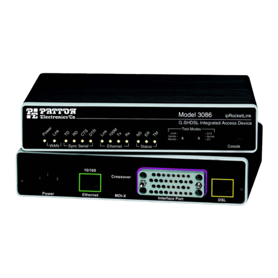
Chapter 1 General Information Chapter contents Model 3086 G.SHDSL IAD overview........................16 General attributes ............................16 G.SHDSL Characteristics ..........................17 Ethernet ................................17 TDM Interface ...............................17 Protocol support .............................17 PPP Support ..............................18 ATM Protocols ...............................18 Protocol Support .............................18 Management ..............................18 Security ................................19 Front Panel Status LEDs, Test Mode Switches, and Console Port ..............19 Console port (outlined in red) ........................21 Rear panel connectors and switches .........................21 Power connector ............................21... -
Page 16: Model 3086 G.shdsl Iad Overview
1 • General Information Model 3086 G.SHDSL Integrated Access Device User Guide Model 3086 G.SHDSL IAD overview The Model 3086 is a G.SHSDSL Integrated Access Device that combines high-speed IP routing and access via ATM/FR/PPP along with TDM data access. The model 3086 offers direct connection to a 10/100Base-T Ethernet environment, a V.35/X.21 Serial direct connection to a router or multiplexer, or a T1, E1, or 64K/G.703 port for connection to local device (e.g., PBX). -
Page 17: G.shdsl Characteristics
Model 3086 G.SHDSL Integrated Access Device User Guide 1 • General Information • Standard 1 year warranty. • Convenient and standard RJ connectors for Ethernet, Line, and Console. G.SHDSL Characteristics • Full duplex 2.3 Mbps speed over 2-wire (in accordance with ETSI/ITU standard G.991.2). 2.3 Mbps to 4.6 Mbps, full duplex, over 2-wire. -
Page 18: Ppp Support
1 • General Information Model 3086 G.SHDSL Integrated Access Device User Guide PPP Support • Point-to-Point Protocol over HDLC • PPPoA (RFC 2364) Point-to-Point Protocol over ATM. • PPPoE (RFC 2516) Client for autonomous network connection. Eliminates the requirement of installing client software on a local PC and allows sharing of the connection across a LAN. -
Page 19: Security
Model 3086 G.SHDSL Integrated Access Device User Guide 1 • General Information • SNMPv1 (RFC 1157) MIB II (RFC 1213) • Quick Start Setup runs through common options to simplify circuit turn-up. • Logging via SYSLOG, and VT-100 console. Console port set at 9600 bps 8/N/1 settings no flow control. •... -
Page 20: Power Green
1 • General Information Model 3086 G.SHDSL Integrated Access Device User Guide Table 3. Status LED descriptions Green ON indicates that power is applied. Off indicates Power that no power is applied. WAN (DSL) Link Green Solid green: connected Off: disconnected Green Green: indicates a binary ‘0’... -
Page 21: Console Port (Outlined In Red)
Model 3086 G.SHDSL Integrated Access Device User Guide 1 • General Information Console port (outlined in red) The unshielded RJ-45 RS-232 console DCE port (EIA-561) with the pin-out listed in the following table: Pin No. Signal Direction Signal Name — Signal Ground Rear panel connectors and switches On the rear panel from left to right are the following:... -
Page 22: Ethernet Port (Outlined In Green)
1 • General Information Model 3086 G.SHDSL Integrated Access Device User Guide Ethernet port (outlined in green) Shielded RJ-45 10Base-T/100Base-TX Ethernet port using pins 1,2,3, & 6. See MDI-X switch for hub or transceiver configuration.The following table defines conditions that occur when the MDI-X switch is in the out position. Pin No. -
Page 23: Product Overview
Chapter 2 Product Overview Chapter contents Product Overview..............................24 Applications Overview ............................24 Internet/Extranet Access ..........................25 IP/FR and TDM Access ..........................25 IP/FR and Voice over DSL ........................25 Metro Intranet Access ..........................26... -
Page 24: Product Overview
2 • Product Overview Model 3086 G.SHDSL Integrated Access Device User Guide Product Overview The Model 3086 IAD operates as a bridge or a router and has three ports for communication: • The Ethernet port—Connects to the LAN side of the connection •... -
Page 25: Internet/Extranet Access
Model 3086 G.SHDSL Integrated Access Device User Guide 2 • Product Overview Internet/Extranet Access While Frame Relay (FR) remains the most economical service to connect multiple corporate locations over PVCs (Private Virtual Connections) at burst and fixed data rates, high speed DSL is becoming the technology of choice for last mile access to FR switches. -
Page 26: Metro Intranet Access
2 • Product Overview Model 3086 G.SHDSL Integrated Access Device User Guide PCM encoded voice from a PBX are carried in split-DSL- bandwidth mode to a Central Office. At a Service Provider location the Model 3096RC separates PCM voice and IP data traffic for transport over the WAN Metro Intranet Access Patton’s Model 3086 symmetrical G.SHDSL modulation scheme, allows deployment in back-to-back configu- rations for Metro Intranet Access with the following benefits. -
Page 27: Quick Start Installation
Chapter 3 Quick Start Installation Chapter contents Hardware installation ............................28 What you will need ............................28 Installing the AC power cord ..........................28 Connecting network cables ..........................29 IP address Quick Start modification ........................30 Web Operation and Configuration .........................30 PC Configuration .............................30 Web Browser .............................30... -
Page 28: Hardware Installation
3 • Quick Start Installation Model 3086 G.SHDSL Integrated Access Device User Guide Hardware installation If you are already familiar with Model 3086 IAD installation and configuration, this chapter will enable you to finish the job quickly. Installation consists of the following: •... -
Page 29: Connecting Network Cables
Model 3086 G.SHDSL Integrated Access Device User Guide 3 • Quick Start Installation To avoid the risk of injury from electric shock, the power cord connected to the IEC-320 connectors must be a grounded power cord. The 3086 power supply automatically adjusts to accept an input voltage from 100 to 240 VAC (50/60 Hz). -
Page 30: Ip Address Quick Start Modification
3 • Quick Start Installation Model 3086 G.SHDSL Integrated Access Device User Guide IP address Quick Start modification The first parameter to change is the IP address from the default IP address of 192.168.1.1/24 (for the CP units) or 192.168.200.11 (for CO units) to your selected IP address. Follow these steps. Comments are in brackets […]. - Page 31 Model 3086 G.SHDSL Integrated Access Device User Guide 3 • Quick Start Installation The Model 3086 home page displays (see Figure 3). Figure 3. Model 3086 home page The Model 3086 menu structure is shown in figure 4 on page 32. Hardware installation...
- Page 32 3 • Quick Start Installation Model 3086 G.SHDSL Integrated Access Device User Guide Figure 4. Model 3086 Menu Structure Hardware installation...
-
Page 33: Basic Application Configurations
Chapter 4 Basic Application Configurations Chapter contents Introduction ................................36 TDM Port................................37 V.35 and X.21 Ports..............................39 Connecting the 3086 serial port to a DTE ......................39 Connecting the 3086 serial port to a DCE ......................39 V.35 interfaces............................39 X.21 interfaces............................39 Configuring the V.35 or X.21 port via DIP switches ..................40 Switch Bank S2 ............................42 Switches S2-1 through S2-7 ........................ - Page 34 4 • Basic Application Configurations Model 3086 G.SHDSL Integrated Access Device User Guide Switch S3-8 ............................52 Web Interface Configuration ........................53 Using the 3086 as a simple modem (TDM data over DSL) ...................54 DIP Switch Configuration ..........................54 CLI configuration ............................54 3086 A CLI configuration .........................54 3086 B CLI configuration .........................55 Web browser configuration ..........................56...
- Page 35 Model 3086 G.SHDSL Integrated Access Device User Guide 4 • Basic Application Configurations Line Probe ..............................63 Using the 3086 in Routed or Bridged applications ....................64 Two stand-alone units directly connected .......................64 Ethernet extension (HDLC – PPPOH) Bridged ..................64 Network Extension (HDLC—PPPoH Routed) ..................67 DSLAM Connections with remote CPE units .......................73 Bridged application configurations to a DSLAM ....................73 RFC 1483 Bridged Configuration.
-
Page 36: Introduction
4 • Basic Application Configurations Model 3086 G.SHDSL Integrated Access Device User Guide Introduction The Model 3086 IAD comes with two data ports: a TDM (V.35, X.21, or T1/E1), and an Ethernet port. TDM port data is not processed by the router or bridge core in the 3086, data is transmitted unprocessed over the DSL link. -
Page 37: Tdm Port
Model 3086 G.SHDSL Integrated Access Device User Guide 4 • Basic Application Configurations The following table shows the parameters that can be configured via the HTTP server using a web browser. Routed WAN Services Bridged WAN Services Web Page Parameter PPPoA IPoA PPPoE... - Page 38 4 • Basic Application Configurations Model 3086 G.SHDSL Integrated Access Device User Guide sented on a female DB-15 connector, while the T1/E1 interface is presented on an RJ-48C jack, additionally the E1 interface is presented on dual BNC. Figure 5 shows the different connectors offered for the serial port. Figure 5.
-
Page 39: V.35 And X.21 Ports
Model 3086 G.SHDSL Integrated Access Device User Guide 4 • Basic Application Configurations V.35 and X.21 Ports The serial port in the 3086 is simple to install. The V.35 interface is wired as a DCE, the X.21 interface can be configured as a DCE (factory default), or as a DTE via internal configuration jumper. -
Page 40: Configuring The V.35 Or X.21 Port Via Dip Switches
4 • Basic Application Configurations Model 3086 G.SHDSL Integrated Access Device User Guide 2. Locate the small daughter board on the 3086 board between the DSL port (RJ-45) connector and the serial port connector (Figure 7 shows location of DTE/DCE daughter board). Figure 7. - Page 41 Model 3086 G.SHDSL Integrated Access Device User Guide 4 • Basic Application Configurations Switch configuration: Switch configuration in the 3086 is to be used in situations where the 3086 functions as a DSL modem carrying TDM (X.21, V.35) data only, without resorting to the use of a PC for configuration. When configuring the Model 3086 via DIP switches, the following conditions apply: •...
-
Page 42: Switch Bank S2
4 • Basic Application Configurations Model 3086 G.SHDSL Integrated Access Device User Guide Switch Bank S2 Table 4 shows the default configuration for switch S2. A description of S2 options follows the table. Table 4. S2 Summary Table Switch Position Function Factory Default Selected Option... -
Page 43: Switch S2-8
Model 3086 G.SHDSL Integrated Access Device User Guide 4 • Basic Application Configurations Data Rate (kbps) 1472 1536 1600 1664 1728 1792 1856 1920 1984 2048 2112 2176 2240 2304 Switch S2-8. S2-8 activates configuration of Model 3086 via DIP switches. Any time the user desires to mod- ify the 3086 configuration available through DIP switches, make the changes to the corresponding switches and then set S2-8, from On to Off position, wait 3-4 seconds and set back to the On position. -
Page 44: Switch S3-3: Transmit Clock Mode
4 • Basic Application Configurations Model 3086 G.SHDSL Integrated Access Device User Guide installed at a Central Office should be set to CO. For point-to-point operation, one unit must be CO while the other must be CP. S3-3 Setting Switch S3-3: Transmit Clock Mode. Use Switches S3-3 to configure the Model 3086 for internal or external clock mode (keep in mind that this setting only affects the operation of the serial port). -
Page 45: T1 Interface Configuration
Model 3086 G.SHDSL Integrated Access Device User Guide 4 • Basic Application Configurations T1 Interface Configuration The 3086 T1 interface can be configured via DIP switches, HTTP/SNMP, or command line interface (CLI). This section discusses DIP switches and HTTP (web server) configuration. For CLI, see Appendix D, “Com- mand Line Interface (CLI) Operation”... -
Page 46: Switches S2-1 Through S2-7
4 • Basic Application Configurations Model 3086 G.SHDSL Integrated Access Device User Guide Switches S2-1 through S2-7. Use Switches S2-1 through S2-7 to set the data rate (see Table 5 on page 43. Each position represents nx64 settings. Data Rate (kbps) 1024 1088 1152... -
Page 47: Switch Bank S3
Model 3086 G.SHDSL Integrated Access Device User Guide 4 • Basic Application Configurations Switch Bank S3 The table below shows the default configuration for switch S3. A description of S3 options follows this table. Table 7. S3 Summary Table Switch Position Function Factory Default Selected Option... -
Page 48: Switch S3-6: Annex
4 • Basic Application Configurations Model 3086 G.SHDSL Integrated Access Device User Guide Switch S3-6: Annex. Annex A and B offer spectral compatibility with T1 and E1 signals respectively, this fea- ture reduces the interference between DSL lines and adjacent E1or T1 lines. For regions where T1 is used, select Annex A. -
Page 49: E1 Interface
Model 3086 G.SHDSL Integrated Access Device User Guide 4 • Basic Application Configurations Line Build Out: Select from 100 ohm (0dB), 100 ohm (-7.5dB), 100 ohm (-15dB), and 100 ohm (-22.5dB). For CSU/DSU application use 100 0dB option, consult your T1 service provider for more information. FDL Mode: Options are ANSI-T1-403, ATT-54016, and Fdl-none. -
Page 50: Dip Switch Configuration
4 • Basic Application Configurations Model 3086 G.SHDSL Integrated Access Device User Guide information and cable requirements. If the E1 connection is made via the BNC connectors, connect the TX BNC of the 3086 to Recive (RX) BNC of the local E1 device, and vice versa. •... -
Page 51: Switch S2-8
Model 3086 G.SHDSL Integrated Access Device User Guide 4 • Basic Application Configurations Data Rate (kbps) 1216 1280 1344 1408 1472 1536 1600 1664 1728 1792 1856 1920 1984 2048 Switch S2-8. S2-8 activates configuration of Model 3086 via DIP switches. Any time the user desires to mod- ify the 3086 configuration available through DIP switches, make the changes to the corresponding switches and then set S2-8, from On to Off position, wait 3-4 seconds and set back to the On position. -
Page 52: Switch S3-3: Transmit Clock Mode
4 • Basic Application Configurations Model 3086 G.SHDSL Integrated Access Device User Guide installed at a Central Office should be set to CO. For point-to-point operation, one unit must be CO while the other must be CP. S3-3 Setting Switch S3-3: Transmit Clock Mode. Use Switches S3-3 to configure the 3086 for internal or external clock mode. -
Page 53: Web Interface Configuration
Model 3086 G.SHDSL Integrated Access Device User Guide 4 • Basic Application Configurations Web Interface Configuration Launch Internet Explorer or similar web browser, type the IP address of the 2603, enter username ‘superuser’ and password ‘superuser’. From the main page click on the E1/T1 option > Configuration. This page allows configuration of E1 parameters as follows: Time Slot Select. -
Page 54: Using The 3086 As A Simple Modem (Tdm Data Over Dsl)
4 • Basic Application Configurations Model 3086 G.SHDSL Integrated Access Device User Guide Using the 3086 as a simple modem (TDM data over DSL) Serial port connection only, Ethernet port not used to send data over DSL but can be used for management. There are three ways to configure the 3086 for serial port operation only: •... -
Page 55: 3086 B Cli Configuration
Model 3086 G.SHDSL Integrated Access Device User Guide 4 • Basic Application Configurations gshdsl set pcmmode Serial fi fi gshdsl set ghsannex AnnexB gshdsl set serialTS 32 fi system config save fi Wait for 'configuration saved' message… Saving configuration… fi Configuration saved. -
Page 56: Web Browser Configuration
4 • Basic Application Configurations Model 3086 G.SHDSL Integrated Access Device User Guide Web browser configuration From the main menu in the 3086, select GSHDSL > Configuration . Enter the selections as shown in the screen below. For Terminal Type , select for 3086 A, and for 3086 B. -
Page 57: Intended Serial Interface Data Rate
Model 3086 G.SHDSL Integrated Access Device User Guide 4 • Basic Application Configurations Intended Serial Interface Data Rate Selects the data rate assigned to the serial port in nx64 kbps increments from 64 kbps to a maximum of 2.3 Mbps. The following conditions apply when configuring the 3086 serial port: •... -
Page 58: Interface Type
4 • Basic Application Configurations Model 3086 G.SHDSL Integrated Access Device User Guide Interface Type Selects between HDLC or ATM transports. This setting must match the transport selected in the “WAN con- nection” menu. When using the 3086 to transport serial data only, select HDLC transport. PCM Mode The PCM mode selection tells the Model 3086 whether the DSL link will carry Serial data (from serial port), Ethernet data (from Ethernet port), or both Serial and Ethernet. -
Page 59: Cli Configuration
Model 3086 G.SHDSL Integrated Access Device User Guide 4 • Basic Application Configurations CLI configuration Configuring the 3086 to transport TDM and IP data concurrently requires use of a Laptop or PC terminal. When carrying IP data, the Model 3086 offers two WAN encapsulation methods: HDLC and ATM. In addi- tion, when connecting two LAN segments over DSL, the 3086 offers options for Routed or Bridged services. -
Page 60: Interface Type
4 • Basic Application Configurations Model 3086 G.SHDSL Integrated Access Device User Guide • For 3086 A at the prompt type gshdsl set terminal central <enter> • For 3086 B type gshdsl set terminal remote fi Interface Type Selects between HDLC and ATM transport. To select HDLC for both 3086 type: gshdsl set interface hdlc <enter>... -
Page 61: Circuit Id
Model 3086 G.SHDSL Integrated Access Device User Guide 4 • Basic Application Configurations figuration option”. Use the drop down menus to enter the required configuration. Once all settings have been selected, click on the button at the bottom of the screen. Configure Circuit ID User can enter up to 30 alphanumeric characters for circuit identification... -
Page 62: Intended Serial Interface Data Rate
4 • Basic Application Configurations Model 3086 G.SHDSL Integrated Access Device User Guide Intended Serial Interface Data Rate Selects the data rate assigned to the serial port in nx64 kbps increments from 64 kbps to a maximum of 2.3 Mbps. The following conditions apply when configuring the 3086 serial port: •... -
Page 63: Interface Type
Model 3086 G.SHDSL Integrated Access Device User Guide 4 • Basic Application Configurations Interface Type Selects between HDLC or ATM transports. This setting must match the transport selected in the “WAN con- nection” menu. When using the 3086 to transport serial data only, select HDLC transport. PCM Mode The PCM mode selection tells the Model 3086 whether the DSL link will carry Serial data (from serial port), Ethernet data (from Ethernet port), or both Serial and Ethernet. -
Page 64: Using The 3086 In Routed Or Bridged Applications
4 • Basic Application Configurations Model 3086 G.SHDSL Integrated Access Device User Guide Using the 3086 in Routed or Bridged applications Two stand-alone units directly connected Ethernet extension (HDLC – PPPOH) Bridged Model 3086 (Remote) Configuration Steps (PPPoH Bridged) From the command line interface (CLI) via the RS-232 control port, fi... - Page 65 Model 3086 G.SHDSL Integrated Access Device User Guide 4 • Basic Application Configurations Verify the settings to be: – Interface = 1 – LLC header mode = dialout – LLC header mode = off – HDLC header mode = on –...
- Page 66 4 • Basic Application Configurations Model 3086 G.SHDSL Integrated Access Device User Guide Change Terminal Type to Central and Interface Type to hdlc. Click on the button. Configure In the Action submenu under G.SHDSL, change Action to , then click on Deactivate Action Return to Action, select...
-
Page 67: Network Extension (Hdlc-Pppoh Routed)
Model 3086 G.SHDSL Integrated Access Device User Guide 4 • Basic Application Configurations – LLC header mode = off – HDLC header mode = on – No authentication – Leave User name and Password blank. Click on Apply 3. Go to in the Configuration Menu, then the submenu G.SHDSL Configuration... - Page 68 4 • Basic Application Configurations Model 3086 G.SHDSL Integrated Access Device User Guide 1. Now you can bring up the web-page management system on your browser by entering the IP address of the 3086. Click on in the > verify that Terminal Type is and Interface Type G.SHDSL Configuration Menu >...
- Page 69 Model 3086 G.SHDSL Integrated Access Device User Guide 4 • Basic Application Configurations Click on Configure 3. Go to [enter Configuration Menu > Configuration > WAN connections > Edit (for PPPoH Routed service) > Edit ‘IP Interface’ > Ipaddr: the WAN IP Address, in this example = 192.168.164.2] > Click on Change Using the 3086 in Routed or Bridged applications...
- Page 70 4 • Basic Application Configurations Model 3086 G.SHDSL Integrated Access Device User Guide Click on > Create the gateway to the remote Configuration Menu > Configuration > IP Routes > Create new Ip V4 Route 3086 by entering the WAN IP address of the remote 3086, in this example, enter 192.168.164.3 in the Gateway field >...
- Page 71 Model 3086 G.SHDSL Integrated Access Device User Guide 4 • Basic Application Configurations 5. Go to G.SHDSL in the Configuration Menu, then the submenu Status. The Modem State should be “deactivated.” (If not, go to the Action and change it to deactivate.) Then in the Action submenu under G.SHDSL, change Action to Start, then click on Action Model 3086 (Central) Configuration Steps (PPPoH Routed)
- Page 72 4 • Basic Application Configurations Model 3086 G.SHDSL Integrated Access Device User Guide Click on in the verify that Terminal Type is remote and Interface Type G.SHDSL Configuration Menu > Configuration > is “hdlc.” If changed, then click on Configure Click on >...
-
Page 73: Dslam Connections With Remote Cpe Units
Model 3086 G.SHDSL Integrated Access Device User Guide 4 • Basic Application Configurations – Cost:1 – Interface:[blank] 5. Go to in the Configuration Menu, then the submenu . The Modem State should be “deacti- G.SHDSL Status vated.” (If not, go to the Action and change it to deactivate.) Then in the Action submenu under G.SHDSL, change Action to Start, then click on Action DSLAM Connections with remote CPE units... - Page 74 4 • Basic Application Configurations Model 3086 G.SHDSL Integrated Access Device User Guide Model 3086 (Remote) Configuration Steps (RFC 1483 Bridged) From the command line interface (CLI) via the RS-232 control port, ip list interfaces fi One IP interface is called ip1 with an IP address of 192.168.1.1 Change the IP address so it is in the same subnet as both PCs.
- Page 75 Model 3086 G.SHDSL Integrated Access Device User Guide 4 • Basic Application Configurations Change Terminal Type to Remote and Interface Type to atm. Click on the button. Configure In the Action submenu under G.SHDSL, change Action to , then click on Action. Deactivate Return to Action, select and click on...
-
Page 76: Pppoh Bridged Configuration
4 • Basic Application Configurations Model 3086 G.SHDSL Integrated Access Device User Guide Leave VCI as 35 and Encapsulation Method as LLC/SNAP. Then click on Apply 3. Go to G.SHDSL in the Configuration Menu, then the submenu Configuration. Leave Terminal Type as Remote, but change Interface Type to atm. Click on the button. - Page 77 Model 3086 G.SHDSL Integrated Access Device User Guide 4 • Basic Application Configurations Click on in the main window, select and click on the button. Create a new service PPPoH_Bridged Configure In the Description field, enter the description you wish. In this example, it is called PPPoH Bridged. –...
- Page 78 4 • Basic Application Configurations Model 3086 G.SHDSL Integrated Access Device User Guide Model 3086 (Central) Configuration Steps (PPPoH Bridged) From the command line interface (CLI) via the RS-232 control port, ip list interfaces fi One IP interface is called ip1 with an IP address of 192.168.1.1 Change the IP address so it is in the same subnet as both PCs.
-
Page 79: Pppoa Bridged (Rfc 2364) Configuration
Model 3086 G.SHDSL Integrated Access Device User Guide 4 • Basic Application Configurations PPPoA Bridged (RFC 2364) Configuration The user data for transmission is in the form of IP packets but encapsulated in a PPP packet, transmitted and received through a PPP session to the connection. The PPP packets are encapsulated according to RFC 2364 for transmission over the ATM link. - Page 80 4 • Basic Application Configurations Model 3086 G.SHDSL Integrated Access Device User Guide – VPI = 0 – VCI = 300 – LLC header mode = off – HDLC header mode = off – No authentication – Leave User name and Password blank. Click on Apply 3.
-
Page 81: Routed Application Configurations To A Dslam
Model 3086 G.SHDSL Integrated Access Device User Guide 4 • Basic Application Configurations – No authentication – Leave User name and Password blank. Click on Apply 3. Go to G.SHDSL in the Configuration Menu, then the submenu Configuration. Leave Terminal Type as Central. Change Interface Type to atm. - Page 82 4 • Basic Application Configurations Model 3086 G.SHDSL Integrated Access Device User Guide 1. Now you can bring up the web-page management system on your browser by entering the IP address of the 3086. Click on G.SHDSL in the Configuration Menu > Configuration > verify that Terminal Type is Central and Interface Type is atm.
- Page 83 Model 3086 G.SHDSL Integrated Access Device User Guide 4 • Basic Application Configurations In the Description field, enter the description you wish. In this example, it is called RFC 1483 Routed. Change the configuration parameters to match the following. Description:RFC 1483 Routed –...
- Page 84 4 • Basic Application Configurations Model 3086 G.SHDSL Integrated Access Device User Guide The other fields should be: – Destination:0.0.0.0 – Gateway:192.168.164.3 – Mask:0.0.0.0 – Cost:1 – Interface:[blank] 4. Go to G.SHDSL in the Configuration Menu, then the submenu Status. The Modem State should be “deactivated.”...
- Page 85 Model 3086 G.SHDSL Integrated Access Device User Guide 4 • Basic Application Configurations Change the IP address so it is in the same subnet as the laptop PC. The laptop’s IP address is 192.168.172.229, so in this example, change the IP address of the 3086 to 192.168.172.3. The default IP mask is 255.255.255.0.
- Page 86 4 • Basic Application Configurations Model 3086 G.SHDSL Integrated Access Device User Guide Click on Action > Select deactivate for Action > Click on the Action button. 2. On the Menu, go to Configuration, then to WAN Connections. Delete both default WAN services already defined. Click on in the main window, select and click on the...
- Page 87 Model 3086 G.SHDSL Integrated Access Device User Guide 4 • Basic Application Configurations 3. Configuration Menu > Configuration > IP Routes > Click on Create new Ip V4 Route > Create the gate- way to the remote 3086 by entering the WAN IP address of the remote 3086, in this example, enter 192.168.164.2 in the Gateway field >...
-
Page 88: Pppoh Routed
4 • Basic Application Configurations Model 3086 G.SHDSL Integrated Access Device User Guide 4. Go to G.SHDSL in the Configuration Menu, then the submenu Status. The Modem State should be “deactivated.” (If not, go to the Action and change it to deactivate.) Then in the Action submenu under G.SHDSL, change Action to Start, then click on Action. - Page 89 Model 3086 G.SHDSL Integrated Access Device User Guide 4 • Basic Application Configurations One IP interface was called ip1 with an IP address of 192.168.1.1 Change it to an IP address which is in the same subnet as the Desktop PC. For example, to 192.168.100.2. The default IP mask is 255.255.255.0. ip set interface ip1 ipaddress 192.168.100.2 255.255.255.0 fi...
- Page 90 4 • Basic Application Configurations Model 3086 G.SHDSL Integrated Access Device User Guide – Username:[blank] – Password:[blank] Click on Configure 3. Go to Configuration Menu > Configuration > WAN connections > Edit (for PPPoH Routed service) > Edit ‘IP Interface’ > Ipaddr: [enter the WAN IP Address, in this example = 192.168.164.2] > Click on Change.
- Page 91 Model 3086 G.SHDSL Integrated Access Device User Guide 4 • Basic Application Configurations 4. Configuration Menu > Configuration > IP Routes > Click on Create new Ip V4 Route > Create the gate- way to the remote 3086 by entering the WAN IP address of the remote 3086, in this example, enter 192.168.164.3 in the Gateway field >...
- Page 92 4 • Basic Application Configurations Model 3086 G.SHDSL Integrated Access Device User Guide 5. Go to G.SHDSL in the Configuration Menu, then the submenu Status. The Modem State should be “deactivated.” (If not, go to the Action and change it to deactivate.) Then in the Action submenu under G.SHDSL, change Action to Start, then click on Action Model 3086 (Central) Configuration Steps (PPPoH Routed)
- Page 93 Model 3086 G.SHDSL Integrated Access Device User Guide 4 • Basic Application Configurations 1. Now you can bring up the web-page management system on your browser by entering the IP address of the 3086. Click on G.SHDSL in the Configuration Menu > Configuration > verify that Terminal Type is Central and Interface Type is hdlc.
- Page 94 4 • Basic Application Configurations Model 3086 G.SHDSL Integrated Access Device User Guide 3. Go to Configuration Menu > Configuration > WAN connections > Edit (for PPPoH Routed service) > Edit ‘IP Interface’ > Ipaddr: [enter the WAN IP Address, in this example = 192.168.164.3] > Click on Change.
-
Page 95: Pppoa Routed (Rfc 2364)
Model 3086 G.SHDSL Integrated Access Device User Guide 4 • Basic Application Configurations PPPoA Routed (RFC 2364) This routed application is very similar to the PPPoA Bridged application. The user data for transmission is in the form of IP packets but encapsulated in a PPP packet, transmitted and received through a PPP session to the connection. - Page 96 4 • Basic Application Configurations Model 3086 G.SHDSL Integrated Access Device User Guide Now you can bring up the web-page management system on your browser by entering the IP address of the 3086. Click on G.SHDSL in the Configuration Menu > Configuration > verify that Terminal Type is Central and Interface Type is atm.
- Page 97 Model 3086 G.SHDSL Integrated Access Device User Guide 4 • Basic Application Configurations 3. In the Configuration Menu, click on Configuration then > WAN Connections > Edit (for the WAN Ser- vice ppp1) > Edit ‘PPP’ and verify or change the following parameters on the Edit PPP webpage. –...
- Page 98 4 • Basic Application Configurations Model 3086 G.SHDSL Integrated Access Device User Guide – Discover Primary DNS:true – Discover Secondary DNS:true – Give DNS to Relay:true – Give DNS to Client:true – Remote DNS:0.0.0.0 – Remote Secondary:0.0.0.0 – LCP Echo Every:10 –...
- Page 99 Model 3086 G.SHDSL Integrated Access Device User Guide 4 • Basic Application Configurations – Class:UBR – Port:atm Click on the button if changes were made. Change 5. Click on Edit ‘IP Interface.’ Verify or change if necessary the following Options parameters. –...
- Page 100 4 • Basic Application Configurations Model 3086 G.SHDSL Integrated Access Device User Guide Now you can bring up the web-page management system on your browser by entering the IP address of the 3086. Click on G.SHDSL in the Configuration Menu> Configuration > verify that Terminal Type is Central and Interface Type is atm.
- Page 101 Model 3086 G.SHDSL Integrated Access Device User Guide 4 • Basic Application Configurations In the Description field, enter the description you wish. In this example, it is called PPPoA Routed. Change the configuration parameters to match the following. – Description:PPPoA Routed –...
- Page 102 4 • Basic Application Configurations Model 3086 G.SHDSL Integrated Access Device User Guide 3. In the Configuration Menu, click on Configuration then > WAN Connections > Edit (for the WAN Ser- vice ppp1) > Edit ‘PPP’ and verify or change the following parameters on the Edit PPP webpage. Parameters in red italics are those requiring changes from the default configuration.
- Page 103 Model 3086 G.SHDSL Integrated Access Device User Guide 4 • Basic Application Configurations – IP Addr from IPCP: true – Discover Primary DNS: false – Discover Secondary DNS: false – Give DNS to Relay: false – Give DNS to Client: false –...
- Page 104 4 • Basic Application Configurations Model 3086 G.SHDSL Integrated Access Device User Guide Click on button. Change DSLAM Connections with remote CPE units...
- Page 105 Model 3086 G.SHDSL Integrated Access Device User Guide 4 • Basic Application Configurations 4. Click on Edit ‘ATM Channel.’ Verify the Options to match the following. (Change if necessary.) – Tx Vci:800 – Tx Vpi:0 – Rx Vci:800 – Rx Vpi:0 –...
- Page 106 4 • Basic Application Configurations Model 3086 G.SHDSL Integrated Access Device User Guide 5. Click on Edit ‘IP Interface.’ Verify or change if necessary the following Options parameters. – Ipaddr:192.168.164.2 – Mask:255.255.255.0 – Dhcp:false – MTU:1500 – Enabled:true Click on the Change button if changes were made. 6.
-
Page 107: Ipoa Routed (Rfc 1577)
Model 3086 G.SHDSL Integrated Access Device User Guide 4 • Basic Application Configurations 7. From the Configuration Menu, click on Configuration > Authentication > Create a new user > enter the information for the following parameters in the webpage Details for the new user. One of these authentica- tion records is created for each remote end user connecting to the Server. - Page 108 4 • Basic Application Configurations Model 3086 G.SHDSL Integrated Access Device User Guide 1. Now you can bring up the web-page management system on your browser by entering the IP address of the 3086. 2. On the Menu, go to Configuration, then to WAN Connections. Delete the factory default WAN services already defined.
- Page 109 Model 3086 G.SHDSL Integrated Access Device User Guide 4 • Basic Application Configurations 3. Returning to the 3086 Configuration Menu, click on Configuration, then IP Routes. – Click on “Create new Ip V4 Route.” – Destination:0.0.0.0 – Gateway:192.168.164.3 – Mask:0.0.0.0 –...
- Page 110 4 • Basic Application Configurations Model 3086 G.SHDSL Integrated Access Device User Guide 4. Go to G.SHDSL in the Configuration Menu, then the submenu Configuration. Change Terminal Type to Central and Interface Type to atm. Click on the Configure button. In the Action submenu under G.SHDSL, change Action to Deactivate, then click on Action DSLAM Connections with remote CPE units...
- Page 111 Model 3086 G.SHDSL Integrated Access Device User Guide 4 • Basic Application Configurations Return to Action, select Start and click on Action Model 3086 (Central) Configuration Steps (IPoA Routed) From the command line interface (CLI) via the RS-232 control port: ip list interfaces fi...
- Page 112 4 • Basic Application Configurations Model 3086 G.SHDSL Integrated Access Device User Guide 3. Returning to the 3086 Configuration Menu, click on Configuration, then IP Routes. Click on “Create new Ip V4 Route.” – Destination:0.0.0.0 – Gateway:192.168.164.2 – Mask:0.0.0.0 – Cost:1 –...
-
Page 113: Specialized Configurations
Chapter 5 Specialized Configurations Chapter contents IP Configurations..............................114 Router ................................114 DHCP Server and Relay ..........................114... -
Page 114: Ip Configurations
5 • Specialized Configurations Model 3086 G.SHDSL Integrated Access Device User Guide IP Configurations Router RIP and RIPv2 Static Route 1. Click on > Configuration, then > IP Routes on the Configuration Menu. 2. On the main web page entitled “Edit Routes,” click on Create new Ip V4 Route 3. - Page 115 Model 3086 G.SHDSL Integrated Access Device User Guide 5 • Specialized Configurations At the bottom of the web page are three options for the DHCP Server Mode: Disabled, DHCP server (default), and DHCP Relay Agent. 2. Click on on the DHCP Server web page to change the configuration for any of the DHCP param- Configure eters.
- Page 116 5 • Specialized Configurations Model 3086 G.SHDSL Integrated Access Device User Guide 4. The IAD may be used as a DHCP Relay Agent if desired. Go to > Configuration Menu > Configuration > DHCP Server. Select DHCP Relay Agent at the bottom of the web page and click on Configure. The DHCP Relay agent page is displayed.
- Page 117 Model 3086 G.SHDSL Integrated Access Device User Guide 5 • Specialized Configurations DNS Relay Mode In the DNS Relay web page, up to 10 DNS server addresses may be added to utilize the DNS servers already being used by the network. 1.
- Page 118 5 • Specialized Configurations Model 3086 G.SHDSL Integrated Access Device User Guide IP Configurations...
-
Page 119: Security
Chapter 6 Security Chapter contents Introduction ................................120 Configuring the IAD ............................120 Configuring the security interfaces........................121 Deleting a Firewall Policy ..........................122 Enabling the Firewall............................123 Firewall Portfilters ...............................123 Security Triggers..............................124 Intrusion Detection System (IDS) ........................126... -
Page 120: Introduction
6 • Security Model 3086 G.SHDSL Integrated Access Device User Guide Introduction Security provides the ability to setup and enforce security policies. The policies define the types of traffic per- mitted to pass through a gateway, either inbound, outbound, or both, and from which origins the traffic may be allowed to enter. -
Page 121: Configuring The Security Interfaces
Model 3086 G.SHDSL Integrated Access Device User Guide 6 • Security The next step in configuring the IAD is adding the default gateway route. Since the WAN IP address of the 3086 modem at the CO site is 192.168.101.2, this will be the gateway for the 3086 modem at the CPE site, the modem we are currently configuring. -
Page 122: Deleting A Firewall Policy
6 • Security Model 3086 G.SHDSL Integrated Access Device User Guide 4. Add one more security interface by repeating step 2. 5. Select Name of the LAN port (ip1) and Interface Type to be internal. Click on Apply. Now the Firewall policies will be added between the security interfaces. Only one Firewall policy, called etoi, is added between the external and internal interfaces. -
Page 123: Enabling The Firewall
Model 3086 G.SHDSL Integrated Access Device User Guide 6 • Security Firewall Policies: ID | Name Type 1 Type 2 | Validator Allow Only ------------------------------------------------------------------- 1 | item0 | external | internal | false ------------------------------------------------------------------- firewall delete policy item0 fi The firewall policy named item0 is now deleted. -
Page 124: Security Triggers
6 • Security Model 3086 G.SHDSL Integrated Access Device User Guide Transport Type Abbreviation IPIP To allow pings between the two PCs: 1. From the Configuration Menu, > Configuration > Security > Firewall Policy Configuration > Port Filters > Add Raw IP Filter 2. - Page 125 Model 3086 G.SHDSL Integrated Access Device User Guide 6 • Security After configuring the FTP portfilter, you can open an ftp session from Remote to Local, however you can issue ftp commands (e.g., login, cd, etc.) but transfer data (e.g., ls, dir, get, put commands). The portfilter allows an ftp control channel but does not allow the use of a secondary data channel for passing data by ftp.
-
Page 126: Intrusion Detection System (Ids)
6 • Security Model 3086 G.SHDSL Integrated Access Device User Guide Intrusion Detection System (IDS) The security feature in the 3086 IAD provides protection from a number of attacks. Some attacks cause a host to be blacklisted (i.e., no traffic from that host is accepted under any circumstances) for a period of time. Other attacks are simply logged. - Page 127 Model 3086 G.SHDSL Integrated Access Device User Guide 6 • Security Sets the duration for blocking all suspicious hosts. The firewall detects when the system is being scanned by a suspicious host attempting to identify any open ports. – Victim Protection Block Duration:Default = 600 seconds (10 minutes). Sets the duration of the block in seconds.
- Page 128 6 • Security Model 3086 G.SHDSL Integrated Access Device User Guide Intrusion Detection System (IDS)
-
Page 129: Nat (Network Address Translation)
Chapter 7 NAT (Network Address Translation) Chapter contents Introduction ................................130 Enabling NAT ..............................130 Global address pool and reserved map ......................131... -
Page 130: Introduction
7 • NAT (Network Address Translation) Model 3086 G.SHDSL Integrated Access Device User Guide Introduction The basic steps for configuring NAT are: 1. Enable NAT between the internal and external interfaces of the firewall. 2. Create global addresses which will be added to the global pool of IP addresses on the WAN interface. 3. -
Page 131: Global Address Pool And Reserved Map
Model 3086 G.SHDSL Integrated Access Device User Guide 7 • NAT (Network Address Translation) Global address pool and reserved map 1. Click on Advanced NAT Configuration… on the web page, “Security Interface Configuration.” 2. Click on the hyperlink Add Global Address Pool. The global IP addresses need to be created and put into the Global Address Pool. - Page 132 7 • NAT (Network Address Translation) Model 3086 G.SHDSL Integrated Access Device User Guide 6. Set the parameters to the following values: – Global IP Address:100.100.100.101 – Internal IP address:10.1.1.2 – Transport Type:all – Port Number:65535(This port number means all port numbers for TCP or UDP protocols will be mapped.) 7.
-
Page 133: Monitoring Status
Chapter 8 Monitoring Status Chapter contents Status LEDs.................................134... -
Page 134: Status Leds
8 • Monitoring Status Model 3086 G.SHDSL Integrated Access Device User Guide Status LEDs The LEDs indicate the status of the Power, the WAN (DSL) inter-modem link, Sync Serial or T1/E1 port, the Ethernet connection, and Status. All LED indicators will present the same looking profile (e.g., clear) when unlit due to being single color, water clear, high efficiency LEDs. -
Page 135: Diagnostics
Chapter 9 Diagnostics Chapter contents Introduction ................................136 Ping..................................136 Software Upgrades...............................136 Configuration ...............................136 Procedure ..............................136 Operating Local Analog Loopback (LAL)—Serial Port Loop................137 Operating Remote Digital Loopback (RDL)—DSL Loop ...................137 T1/E1 Diagnostics...............................138 Network Loop ..............................138 T1/E1 Local Loop ............................139 QRSS—BIT Error Rate Diagnostics ......................140 T1/E1 connection Status ..........................141 Alarms ..............................141 Transceiver Status. -
Page 136: Introduction
9 • Diagnostics Model 3086 G.SHDSL Integrated Access Device User Guide Introduction The Model 3086 offers three sets of diagnostics: Local Analog Loopback (serial port loop), Remote Digital Loopback (DSL loop), and T1/E1 Loops for the Model 3086/K. Some tests can be activated physically from the front panel, or via the CLI/Web management menus Ping The ping command is executed from the Command Line Interface (CLI). -
Page 137: Operating Local Analog Loopback (Lal)-Serial Port Loop
Model 3086 G.SHDSL Integrated Access Device User Guide 9 • Diagnostics – Npimage – Key – Initbun – Im.conf – Tftpupdt.rbt – Tftpupdt.end – Script.bat 2. Connect the control (console) port of the unit to a PC. 3. Connect the Ethernet port to the appropriate device where the upload package will be stored. 4. -
Page 138: T1/E1 Diagnostics
9 • Diagnostics Model 3086 G.SHDSL Integrated Access Device User Guide keyboard of the local terminal will appear on the local terminal screen after having been passed to the remote Model 3086 and looped back). See Figure 13. Local 3086 Remote 3086 /1 0 /1 0... -
Page 139: T1/E1 Local Loop
Model 3086 G.SHDSL Integrated Access Device User Guide 9 • Diagnostics To set the 3086 T1/E1 port in Network Loopback test, do the following: 1. Go to the 3086 Main page, select E1/T1. Next, click on Test Modes, select network Loop using the drop down menu, click on the button. -
Page 140: Qrss-Bit Error Rate Diagnostics
9 • Diagnostics Model 3086 G.SHDSL Integrated Access Device User Guide 1. Go to the 3086 Main page, select E1/T1. Next, click on Test Modes, select local Loop using the drop down menu, click on the button. Activate Test Mode 2. -
Page 141: T1/E1 Connection Status
Model 3086 G.SHDSL Integrated Access Device User Guide 9 • Diagnostics T1/E1 connection Status The 3086 E1/T1 status page displays a number of alarms conditions, Transceiver status, and statistics. The information displayed in this page is of use for monitoring and troubleshooting network problems when the 3086 T1/E1 interface is connected directly to a Telco network Alarms The status page shows condition and alarm for the following:... -
Page 142: Bit Error Rate (V.52) Diagnostics
9 • Diagnostics Model 3086 G.SHDSL Integrated Access Device User Guide BIT Error Rate (V.52) Diagnostics The Model 3086 offers a V.52 Bit Error Rate (BER) 511 test pattern. This test pattern may be invoked along with the LAL and RDL tests to evaluate the unit(s) and the DSL communication links. When a 511 test is invoked, the 3086 generates a pseudo-random pattern of 511 bits using a mathematical polynomial. -
Page 143: Contacting Patton For Assistance
Chapter 10 Contacting Patton for assistance Chapter contents Introduction ................................144 Contact information............................144 Warranty Service and Returned Merchandise Authorizations (RMAs)..............144 Warranty coverage ............................144 Out-of-warranty service ...........................144 Returns for credit ............................144 Return for credit policy ...........................145 RMA numbers ..............................145 Shipping instructions ..........................145... -
Page 144: Introduction
10 • Contacting Patton for assistance Model 3086 G.SHDSL Integrated Access Device User Guide Introduction This chapter contains the following information: • “Contact information”—describes how to contact PATTON technical support for assistance. • “Warranty Service and Returned Merchandise Authorizations (RMAs)”—contains information about the RAS warranty and obtaining a return merchandise authorization (RMA). -
Page 145: Return For Credit Policy
Model 3086 G.SHDSL Integrated Access Device User Guide 10 • Contacting Patton for assistance Return for credit policy • Less than 30 days: No Charge. Your credit will be issued upon receipt and inspection of the equipment. • 30 to 60 days: We will add a 20% restocking charge (crediting your account with 80% of the purchase price). - Page 146 10 • Contacting Patton for assistance Model 3086 G.SHDSL Integrated Access Device User Guide Warranty Service and Returned Merchandise Authorizations (RMAs)
- Page 147 Appendix A Compliance information Chapter contents Compliance .................................148 EMC ................................148 Safety ................................148 PSTN Regulatory ............................148 Radio and TV Interference (FCC Part 15) ......................148 CE Declaration of Conformity ..........................148 Authorized European Representative ........................149 FCC Part 68 (ACTA) Statement .........................149 Industry Canada Notice ............................149...
-
Page 148: A Compliance Information
Model 3086 G.SHDSL Integrated Access Device User Guide A • Compliance information Compliance • FCC Part 15, Class A • EN55022, Class A • EN55024 Safety • UL60950-1/CSA C22.2 No. 60950-1 • IEC/EN 60950-1 • AS/NZS 60950-1 PSTN Regulatory • FCC Part 68 •... -
Page 149: Authorized European Representative
Model 3086 G.SHDSL Integrated Access Device User Guide A • Compliance information Authorized European Representative D R M Green European Compliance Services Limited. Avalon House, Marcham Road Abingdon, Oxon OX14 1UD, UK FCC Part 68 (ACTA) Statement This equipment complies with Part 68 of FCC rules and the requirements adopted by ACTA. On the bottom side of this equipment is a label that contains—among other information—a product identifier in the format US: AAAEQ##TXXXX. - Page 150 Model 3086 G.SHDSL Integrated Access Device User Guide A • Compliance information some situations. Repairs to some certified equipment should be made by an authorized maintenance facility designated by the supplier. Any repairs or alterations made by the user to this equipment, or equipment mal- functions, may give the telecommunications company cause to request the user to disconnect the equipment.
- Page 151 Appendix B Specifications Chapter contents General Characteristics ............................152 G.SHDSL Characteristics............................152 Ethernet ................................152 Sync Serial Interface ............................153 T1/E1 Interface (3086/RIK and RIT models only) .....................153 64K/G.703 Port (3086/RIF Model) ........................153 Protocol Support ..............................153 PPP Support................................154 ATM Protocols..............................154 Management ...............................154 Security ................................155 Compliance Standard Requirements........................155 Australia Specific .............................155 Dimensions .................................155...
-
Page 152: B Specifications
B • Specifications Model 3086 G.SHDSL Integrated Access Device User Guide General Characteristics • Compact low-cost plug and play IAD • 10/100 Ethernet • Unlimited host support. • Comprehensive hardware diagnostics, works with any operating system, easy maintenance and effortless installation. -
Page 153: Sync Serial Interface
Model 3086 G.SHDSL Integrated Access Device User Guide B • Specifications Sync Serial Interface • ITU X.21 or V.35 interface • Available with Female M34, DB-25, and DB-15 connectors • User configurable DTE/DCE for X.21 T1/E1 Interface (3086/RIK and RIT models only) •... -
Page 154: Ppp Support
B • Specifications Model 3086 G.SHDSL Integrated Access Device User Guide • uPNP controlled device for seamless networked device interconnectivity and Windows XP integration. • IGMPv2 Proxy support (RFC 2236). • Frame Relay with Annex A/D/LMI, RFC 1490 MpoFR and FRF.12 Fragmentation. PPP Support •... -
Page 155: Security
Model 3086 G.SHDSL Integrated Access Device User Guide B • Specifications Security • Packet filtering firewall for controlled access to and from LAN/WAN. Support for 255 rules in 32 filter sets. 16 individual connection profiles. • DoS Detection/protection. Intrusion detection, Logging of session, blocking and intrusion events and Real- Time alerts. - Page 156 B • Specifications Model 3086 G.SHDSL Integrated Access Device User Guide • Fuse rating: 250 Volts, 400 mA, time delay Connect the equipment to a 36–60 VDC source that is electri- cally isolated from the AC source. The 36–60 VDC source is to be reliably connected to earth.
- Page 157 Appendix C Cable Recommendations Chapter contents DSL Cable................................158 Ethernet Cable ..............................158 Adapter................................158...
-
Page 158: C Cable Recommendations
C • Cable Recommendations Model 3086 G.SHDSL Integrated Access Device User Guide DSL Cable 10 foot (3 m), RJ-11/RJ-11 (refer to “RJ-11 non-shielded port” on page 160) Ethernet Cable Ethernet cable (P/N 10-2500) (refer to “RJ-45 shielded 10/100 Ethernet port” on page 160) Adapter EIA-561 to DB-9 (P/N 16F-561) (refer to “RJ-45 non-shielded RS-232 console port (EIA-561)”... -
Page 159: D Physical Connectors
Appendix D Physical Connectors Chapter contents RJ-45 shielded 10/100 Ethernet port........................160 RJ-11 non-shielded port ............................160 RJ-45 non-shielded RS-232 console port (EIA-561)....................160 Serial port................................161 V.35 (M/34 Connector) ..........................161 V.35 (DB-25 Female Connector) ........................161 X.21 (DB-15 Connector) ..........................162 E1/T1 (RJ-48C Connector) ..........................162 Power input.................................162... -
Page 160: Rj-45 Shielded 10/100 Ethernet Port
D • Physical Connectors Model 3086 G.SHDSL Integrated Access Device User Guide RJ-45 shielded 10/100 Ethernet port Assuming the MDI-X switch is in the out position. Pin No. Signal Direction Signal Name Output Output Input Input RJ-11 non-shielded port Single twisted-pair (TP) for full-duplex transmission. The signals are not polarity sensitive. Pin No. -
Page 161: Serial Port
Model 3086 G.SHDSL Integrated Access Device User Guide D • Physical Connectors Serial port V.35 (M/34 Connector) Pin # Signal GND (Earth Ground/Shield) SGND (Signal Ground) CTS (DCE Source) DSR (DCE Source, Always On) CD (DCE Source) LL (Local Loop, DTE Source) TM (Test Mode Indicator, DCE Source) RL (Remote Loop, DTE Source) TD (Transmit Data +, DTE Source) -
Page 162: Connector)
D • Physical Connectors Model 3086 G.SHDSL Integrated Access Device User Guide Pin # Signal TD/(Transmit Data-A, DTE Source) TC(Transmitter Clock-B, DCE Source) RD (Receive Data-A, DCE Source) RC (Receiver Clock-A, DCE Source) LL (Local LIne Loop) RTS/(Request to Send-B, DTE Source) DTR (Data Terminal Ready-A, DTE Source) RL (Remote Loopback) DSR/ (Data Set Ready-B, DCE Source) -
Page 163: E Command Line Interface (Cli) Operation
Appendix E Command Line Interface (CLI) Operation Chapter contents Introduction ................................164 CLI Terminology ..............................164 Local (VT-100 emulation) ..........................164 Remote (Telnet) ............................164 Using the Console ............................165 Administering user accounts ..........................166 Adding new users ............................166 Setting user passwords ...........................166 Changing user settings ..........................167 Controlling login access ..........................167 Controlling user access ..........................167 G.SHDSL Commands: ..........................167... -
Page 164: Introduction
E • Command Line Interface (CLI) Operation Model 3086 G.SHDSL Integrated Access Device User Guide Introduction The modem configuration and status can also be view and modified through the console, which is accessible through the RS-232 serial port or through a Telnet session over Ethernet. CLI Terminology In order to use the CLI commands, you need to understand the following CLI terms: •... -
Page 165: Using The Console
Model 3086 G.SHDSL Integrated Access Device User Guide E • Command Line Interface (CLI) Operation Using the Console The console commands needed for the various modes of operation are described in later sections. In this sub- section are the most basic commands needed for console operation. By entering “?”... -
Page 166: Administering User Accounts
E • Command Line Interface (CLI) Operation Model 3086 G.SHDSL Integrated Access Device User Guide clear list Æ ip interface ip1 list ? secondaryipaddresses Æ ip interface ip1 list secondaryipaddresses ? ip interface ip1 list secondaryipaddresses <enter> Secondary IP addresses for interface: ip1 ID | IP Address -----|-----------------... -
Page 167: Changing User Settings
Model 3086 G.SHDSL Integrated Access Device User Guide E • Command Line Interface (CLI) Operation Enter the new password twice as prompted: Enter new password: *** Again to verify: *** fi Note No check is made for any current password which may have been set for the user. -
Page 168: To Establish The Dsl Link
E • Command Line Interface (CLI) Operation Model 3086 G.SHDSL Integrated Access Device User Guide Example: To read the attribute ‘Version’: gshdsl show Version To set data rate to 256K (4 * 64K): gshdsl set DSLRateTS To set terminal type to CPE mode: gshdsl set terminal remote To show the current terminal type: gshdsl show terminal... - Page 169 Model 3086 G.SHDSL Integrated Access Device User Guide E • Command Line Interface (CLI) Operation Default Setting of the unit Terminal: Remote Interface: Hdlc DataRateN: DataRateI: Administering user accounts...
- Page 170 E • Command Line Interface (CLI) Operation Model 3086 G.SHDSL Integrated Access Device User Guide Administering user accounts...
-
Page 171: F Interworking Functions Information
Appendix F Interworking Functions Information Chapter contents Introduction ................................173 Frame Relay Local Management Interface ......................173 LMI Configuration Options: ........................173 managementType: (Default Value: no_maintenance) ................173 MgtState ..............................174 mgtAutoStart: (Default Value: FALSE) ....................174 T391_Value: (Default Value: 10) ......................174 T392_Value: (Default Value: 16) ......................174 fullReportCycle: (Default Value: 6) ......................174 netErrorWindowSize: (Default Value: 4) ....................174 netMaxErrors: (Default Value: 3) ......................174... - Page 172 F • Interworking Functions Information Model 3086 G.SHDSL Integrated Access Device User Guide Understanding the Channel Level View ....................186 Set Configuration Variables associated with the Channels ...............187 Web Configuration Methods for FRF.5 Port and Channel Level Configuration ...........187 Port Level Information Screen .........................188 Channel Level Information Screen ......................189 Packet Information Screen ........................189 Frame Relay (Ethernet Based) Operations ......................190...
-
Page 173: Introduction
Model 3086 G.SHDSL Integrated Access Device User Guide F • Interworking Functions Information Introduction This appendix describes the Frame Relay Interworking functions (IWF) that are available on the Model 3086. The following information describes how to use and operate the following Frame Relay Interworking feature sets: •... -
Page 174: Mgtstate
F • Interworking Functions Information Model 3086 G.SHDSL Integrated Access Device User Guide • 933A_Network: The ITU Q.933 protocol will be used. The unit will operate as the Network side of the connection • 933A_User: The ITU Q.933 protocol will be used. The unit will operate as the User side of the connection •... -
Page 175: Cli Configuration Methods
Model 3086 G.SHDSL Integrated Access Device User Guide F • Interworking Functions Information CLI Configuration Methods The following describes how to configure the LMI using the CLI. All LMI commands are contained under the “lmi” directive of the CLI interface. The following options are available: Show current configuration Command: “lmi show”... -
Page 176: Web Configuration Methods
F • Interworking Functions Information Model 3086 G.SHDSL Integrated Access Device User Guide Web Configuration Methods The following describes how to configure the LMI using the web interface. All LMI configuration variables are contained under the “LMI Management” window found through the IWF link. The following image shows the configuration variables available. -
Page 177: Fecn Mapping
Model 3086 G.SHDSL Integrated Access Device User Guide F • Interworking Functions Information • Always_one: – Frame Relay: All Frame Relay packets will have the DE field in the header set to a constant value of 1. – ATM: All ATM cells will have the CLPI field set to a constant value of 1. •... -
Page 178: Frs Name
F • Interworking Functions Information Model 3086 G.SHDSL Integrated Access Device User Guide specification. See figure 16 for the encapsulation types and includes an example where a Routed IP packet is received on both the Frame Relay and ATM sides of the connection. When the packet is received is checked against the known PID fields, and then the packet is routed to the appropriate encapsulation conversion station before being sent out the opposite interface. -
Page 179: Cli Configuration Method
Model 3086 G.SHDSL Integrated Access Device User Guide F • Interworking Functions Information The Frame Relay Service Interworking functions on the Patton Electronics Model 3086FR are also defined as sixty-four channels. Each channel creates a connection between a single DLCI on the Frame Relay network and a VPI/VCI on the ATM network. -
Page 180: Set Variable Attributes On A Specified Channel
F • Interworking Functions Information Model 3086 G.SHDSL Integrated Access Device User Guide Note After the first several letters of the command are typed pressing the Tab key will tell the system to complete the variable or command name. The frs set group command allows the user to setup the configuration of the group variables. The following example could be used to set the DEMapping variable to “convert”. -
Page 181: Group/Channel Level Configuration Screen
Model 3086 G.SHDSL Integrated Access Device User Guide F • Interworking Functions Information “Group #” column along the left side of the screen is a hyperlink that will bring up detailed configuration information about each group and the channels available in the group. Group/Channel Level Configuration Screen By selecting the “Group #”... -
Page 182: Frame Relay Network Interworking (Frf.5)
F • Interworking Functions Information Model 3086 G.SHDSL Integrated Access Device User Guide Figure 18. FRF.8 Channel Level Configuration Screen Figure 19. FRF.8 Channel Level Packet Information Frame Relay Network Interworking (FRF.5) Frame Relay Networking Interworking (FRF.5) is a conversion mechanism by which Frame Relay networks can communicate with ATM networks and the conversion is not visible to the Frame Relay side of the net- work. -
Page 183: Port Level Configuration Options
Model 3086 G.SHDSL Integrated Access Device User Guide F • Interworking Functions Information Port Level Configuration Options: Ports are used to define the lower level Interworking Functions. The port configuration will define the follow- ing variables: • VPI—Virtual Path Identifier: ATM side Virtual Path Identifier for the specified connection. •... -
Page 184: Channel Level Configuration Options
F • Interworking Functions Information Model 3086 G.SHDSL Integrated Access Device User Guide • FRS state: The state variable allows the user to enable or disable the port for operation. Note that port level configuration variables are not changeable “on the fly”. If it is required that configuration changes are required, the user should disable the port, make the configuration changes, and then re-enable the port. -
Page 185: Cli Configuration Methods For Port Level Management
Model 3086 G.SHDSL Integrated Access Device User Guide F • Interworking Functions Information – not active: No information has been received from the management port related to this channel CLI Configuration Methods for Port Level Management The following information can be used to configure the Port Level information associated with the FRN con- nections. -
Page 186: Set Configuration Variables Associated With The Specified Port
F • Interworking Functions Information Model 3086 G.SHDSL Integrated Access Device User Guide FRN Rx Packets: 145/0 FRN Network Mgt: lmi_both FRN Net Mgt State: port_mgt_UP Channel Level Information: --------------------------------------------------------------------- |Chn1 |DLCI|Net DLCI|Activate| Tx Pkt G/B | Rx Pkt G/B |Status |chn1 |100 |0 |enable | 0/0 | 0/0... -
Page 187: Set Configuration Variables Associated With The Channels
Model 3086 G.SHDSL Integrated Access Device User Guide F • Interworking Functions Information must first define the port number that is being configured and then the channel number that is being config- ured. The following chart shows how the ports and channels are viewed by the system: Set Configuration Variables associated with the Channels Command: frn set port# channel # <variable>... -
Page 188: Port Level Information Screen
F • Interworking Functions Information Model 3086 G.SHDSL Integrated Access Device User Guide Once “FRN Setup (FRF.5)” is selected the Port Level Overview screen is displayed as shown below. The screen gives an overview of the FRN connections that are available. Each Port Number in the left column is a hyperlink that will display a more detailed view of the port along with the configuration of the channel level information. -
Page 189: Channel Level Information Screen
Model 3086 G.SHDSL Integrated Access Device User Guide F • Interworking Functions Information Channel Level Information Screen The Channel Level configuration section of the screen allows the user to setup and configure the individual channels associated with the specified port. Note that in the screen show below only a single channel is avail- able for configuration. -
Page 190: Frame Relay (Ethernet Based) Operations
F • Interworking Functions Information Model 3086 G.SHDSL Integrated Access Device User Guide Frame Relay (Ethernet Based) Operations Ethernet based (or basic) Frame Relay is also available within the Patton Electronics Model 3086. This Frame Relay service can be used in a similar fashion to other Ethernet based transports within the system such as PPP or the Ethernet transport. -
Page 191: Clear All Frame Relay Transports
Model 3086 G.SHDSL Integrated Access Device User Guide F • Interworking Functions Information • Port: This variable defines the low layer port that will be used to transport data across the frame relay inter- face. For routed application the “frf” port should be used. For bridged applications the “fr” port should be used. -
Page 192: Web Based Configuration Of The Frame Relay Channel
F • Interworking Functions Information Model 3086 G.SHDSL Integrated Access Device User Guide Web Based Configuration of the Frame Relay Channel This section defines the configuration of the Frame Relay Service through the web interface. The Frame Relay channel is created through the Configuration->WAN link. Serial Interface Configuration This section defines the configuration options available for the serial interface on the Model 3086. -
Page 193: Cli Configuration Methods
Model 3086 G.SHDSL Integrated Access Device User Guide F • Interworking Functions Information CLI Configuration Methods The following section defines how to configure the serial interface using the CLI. All serial interface functions are available under the “serial” directive of the CLI. Set configuration variable Command: serial set <variable>... -
Page 194: Web Interface Configurations
F • Interworking Functions Information Model 3086 G.SHDSL Integrated Access Device User Guide > serial rxClkInv: > Allows the user to invert the clock source > options: normal - use normal clock > inverted - use the inverted version of the clock >... -
Page 195: Trace Route From The Cli Interface
Model 3086 G.SHDSL Integrated Access Device User Guide F • Interworking Functions Information Trace Route from the CLI Interface The Trace Route feature is also available from the “ip” directive in the CLI interface. There are three com- mands available as shown below: Define Usage: “ip traceroute”... -
Page 196: Ping And Traceroute From The Web Interface
F • Interworking Functions Information Model 3086 G.SHDSL Integrated Access Device User Guide Ping and traceroute from the web interface: Both the Ping and Traceroute features are available from the web interface on the Model 3086. The following screen capture show the output of a ping command that was initiated. The ping and traceroute commands can be found by following the “System”...
Need help?
Do you have a question about the ipRocketLink 3086 and is the answer not in the manual?
Questions and answers