Sign In
Upload
Manuals
Brands
Patton electronics Manuals
Network Hardware
ipRocketLink IAD 3086
Patton electronics ipRocketLink IAD 3086 Manuals
Manuals and User Guides for Patton electronics ipRocketLink IAD 3086. We have
3
Patton electronics ipRocketLink IAD 3086 manuals available for free PDF download: User Manual, Quick Start Manual, Specification Sheet
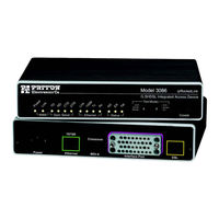
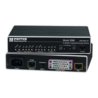
Patton electronics ipRocketLink IAD 3086 User Manual (196 pages)
G.SHDSL Integrated Access Device
Brand:
Patton electronics
| Category:
Network Hardware
| Size: 9 MB
Table of Contents
User Guide
1
Warranty Information
2
Table of Contents
3
Contents
3
About this Guide
11
Audience
11
Structure
11
Precautions
12
Safety When Working with Electricity
13
Factory Default Parameters
13
Typographical Conventions Used in this Document
14
General Conventions
14
Mouse Conventions
14
General Information
15
Chapter 1 General Information
16
Model 3086 G.SHDSL IAD Overview
16
General Attributes
16
G.SHDSL Characteristics
17
Ethernet
17
TDM Interface
17
Protocol Support
17
PPP Support
18
ATM Protocols
18
Protocol Support
18
Management
18
Security
19
Front Panel Status Leds, Test Mode Switches, and Console Port
19
Power Green
20
Console Port (Outlined in Red)
21
Rear Panel Connectors and Switches
21
48 VDC Power Supply
21
AC Universal Power Supply
21
Power Connector
21
Ethernet Port (Outlined in Green)
22
Line Port (Outlined in Yellow)
22
MDI-X
22
Product Overview
23
Chapter 2 Product Overview
24
Product Overview
24
Applications Overview
24
Internet/Extranet Access
25
IP/FR and TDM Access
25
IP/FR and Voice over DSL
25
Metro Intranet Access
26
Quick Start Installation
27
Chapter 3 Quick Start Installation
28
Hardware Installation
28
What You will Need
28
Installing the AC Power Cord
28
Connecting Network Cables
29
IP Address Quick Start Modification
30
Web Operation and Configuration
30
PC Configuration
30
Web Browser
30
Basic Application Configurations
33
Chapter 4 Basic Application Configurations
36
Introduction
36
TDM Port
37
V.35 and X.21 Ports
39
Connecting the 3086 Serial Port to a DTE
39
Connecting the 3086 Serial Port to a DCE
39
V.35 Interfaces
39
Configuring the V.35 or X.21 Port Via DIP Switches
40
Switch Bank S2
42
Switches S2-1 through S2-7
42
Switch Bank S3
43
Switch S2-8
43
Switch S3-1: CO/CP Selection
43
Switch S3-3: Transmit Clock Mode
44
T1 Interface
44
T1 Interface Connection
44
T1 Interface Configuration
45
DIP Switch Configuration
45
Switch Bank S2
45
Switch S2-8
46
Switches S2-1 through S2-7
46
Switch Bank S3
47
Switch S3-1: CO/CP Selection
47
Switch S3-3: Transmit Clock Mode
47
Switch S3 Applies to E1 Applications, for T1 Applications this Switch Is Ignored
48
Switch S3-6: Annex
48
Switch S3-7
48
Switch S3-8
48
Web Interface Configuration
48
E1 Interface
49
E1 Interface Connection
49
DIP Switch Configuration
50
Switch Bank S2
50
Switch Bank S3
51
Switch S2-8
51
Switch S3-1: CO/CP Selection
51
Switch S3-3: Transmit Clock Mode
52
Switch S3-6: Annex
52
Switch S3-7
52
Switch S3-8
52
Web Interface Configuration
53
Using the 3086 as a Simple Modem (TDM Data over DSL)
54
DIP Switch Configuration
54
CLI Configuration
54
3086 A CLI Configuration
54
3086 B CLI Configuration
55
Web Browser Configuration
56
Actual DSL Rate
56
Circuit ID
56
Clear Error Counters
56
Intended DSL Data Rate
56
DSL Rate: Number of I Bit
57
Intended Serial Interface Data Rate
57
Terminal Type
57
Annex Type
58
Interface Type
58
Line Probe
58
Loopback
58
PCM Mode
58
PCM Receive Polarity
58
PCM Transmit Polarity
58
TDM Plus Ethernet Traffic
58
CLI Configuration
59
Assigning Bandwidth to Serial and Ethernet Ports
59
Central or Remote Terminal (Master/Slave)
59
Selecting PCM Mode
59
Selecting the DSL Link Speed
59
Annex Type
60
Interface Type
60
Web Browser Configuration
60
Actual DSL Rate
61
Circuit ID
61
Clear Error Counters
61
Intended DSL Data Rate
61
DSL Rate: Number of I Bit
62
Intended Serial Interface Data Rate
62
Terminal Type
62
Annex Type
63
Interface Type
63
Line Probe
63
Loopback
63
PCM Mode
63
PCM Receive Polarity
63
PCM Transmit Polarity
63
Using the 3086 in Routed or Bridged Applications
64
Two Stand-Alone Units Directly Connected
64
Ethernet Extension (HDLC - PPPOH) Bridged
64
Network Extension (HDLC-Pppoh Routed)
67
DSLAM Connections with Remote CPE Units
73
Bridged Application Configurations to a DSLAM
73
RFC 1483 Bridged Configuration
73
Pppoh Bridged Configuration
76
Pppoa Bridged (RFC 2364) Configuration
79
Routed Application Configurations to a DSLAM
81
RFC 1483 Routed
81
Pppoh Routed
88
Pppoa Routed (RFC 2364)
95
Ipoa Routed (RFC 1577)
107
Specialized Configurations
113
IP Configurations
114
DHCP Server and Relay
114
Router
114
Security
119
Chapter 6 Security
120
Introduction
120
Configuring the IAD
120
Configuring the Security Interfaces
121
Deleting a Firewall Policy
122
Enabling the Firewall
123
Firewall Portfilters
123
Security Triggers
124
Intrusion Detection System (IDS)
126
NAT (Network Address Translation)
129
Introduction
130
Enabling NAT
130
Global Address Pool and Reserved Map
131
Monitoring Status
133
Status Leds
134
Diagnostics
135
Chapter 9 Diagnostics
136
Introduction
136
Ping
136
Software Upgrades
136
Configuration
136
Procedure
136
Operating Local Analog Loopback (LAL)-Serial Port Loop
137
Operating Remote Digital Loopback (RDL)-DSL Loop
137
T1/E1 Diagnostics
138
Network Loop
138
T1/E1 Local Loop
139
QRSS-BIT Error Rate Diagnostics
140
T1/E1 Connection Status
141
Alarms
141
E1/T1 DS0 Monitor
141
FDL Statistics (T1 Only)
141
Transceiver Status
141
BIT Error Rate (V.52) Diagnostics
142
Contacting Patton for Assistance
143
Introduction
144
Contact Information
144
Warranty Service and Returned Merchandise Authorizations (Rmas)
144
Out-Of-Warranty Service
144
Returns for Credit
144
Warranty Coverage
144
Return for Credit Policy
145
RMA Numbers
145
Shipping Instructions
145
A Compliance Information
148
Compliance
148
Emc
148
PSTN Regulatory
148
Safety
148
Radio and TV Interference (FCC Part 15)
148
CE Declaration of Conformity
148
Authorized European Representative
149
FCC Part 68 (ACTA) Statement
149
Industry Canada Notice
149
Appendix B Specifications
152
General Characteristics
152
G.SHDSL Characteristics
152
Ethernet
152
Sync Serial Interface
153
T1/E1 Interface (3086/RIK and RIT Models Only)
153
G.703 Port (3086/RIF Model)
153
Protocol Support
153
PPP Support
154
ATM Protocols
154
Management
154
Security
155
Compliance Standard Requirements
155
Australia Specific
155
Dimensions
155
Power and Power Supply Specifications
155
AC Universal Power Supply
155
48 VDC Power Supply
155
B Specifications
152
C Cable Recommendations
158
DSL Cable
158
Ethernet Cable
158
Adapter
158
D Physical Connectors
159
Appendix D Physical Connectors
160
RJ-45 Shielded 10/100 Ethernet Port
160
RJ-11 Non-Shielded Port
160
Non-Shielded RS-232 Console Port (EIA-561)
160
Serial Port
161
M/34 Connector)
161
Female Connector)
161
Connector)
162
E1/T1 (RJ-48C Connector)
162
Power Input
162
E Command Line Interface (CLI) Operation
163
Appendix E Command Line Interface (CLI)
164
Introduction
164
CLI Terminology
164
Local (VT-100 Emulation)
164
Remote (Telnet)
164
Using the Console
165
Administering User Accounts
166
Adding New Users
166
Setting User Passwords
166
Changing User Settings
167
Controlling Login Access
167
Controlling User Access
167
G.SHDSL Commands
167
To Establish the DSL Link
168
F Interworking Functions Information
171
Appendix F Interworking Functions Information
173
Introduction
173
Frame Relay Local Management Interface
173
LMI Configuration Options
173
Managementtype: (Default Value: No_Maintenance)
173
Fullreportcycle: (Default Value: 6)
174
Mgtautostart: (Default Value: FALSE)
174
Mgtstate
174
Neterrorwindowsize: (Default Value: 4)
174
Netmaxerrors: (Default Value: 3)
174
T391_Value: (Default Value: 10)
174
T392_Value: (Default Value: 16)
174
Usererrorwindowsize: (Default Value: 4)
174
Usermaxerrors: (Default Value: 3)
174
CLI Configuration Methods
175
Set Configuration Variable
175
Show Current Configuration
175
Web Configuration Methods
176
Frame Relay Service Interworking (FRF.8)
176
FRS Configuration Options
176
DE Mapping
176
FECN Mapping
177
Translation Mode
177
FRS Name
178
CLI Configuration Method
179
Set Variable Attributes on a Specified Group
179
Show One of the Eight Groups
179
Set Variable Attributes on a Specified Channel
180
Web Configuration Methods
180
FRS Overview Screen
180
Group/Channel Level Configuration Screen
181
Frame Relay Network Interworking (FRF.5)
182
FRN Configuration Options
182
Port Level Configuration Options
183
Channel Level Configuration Options
184
CLI Configuration Methods for Port Level Management
185
List All Ports Available to the System
185
Show Detailed Information about a Specific Port
185
Configuration Management of the Channel Level Variables
186
Set Configuration Variables Associated with the Specified Port
186
Understanding the Channel Level View
186
Set Configuration Variables Associated with the Channels
187
Web Configuration Methods for FRF.5 Port and Channel Level Configuration
187
Port Level Information Screen
188
Channel Level Information Screen
189
Packet Information Screen
189
Frame Relay (Ethernet Based) Operations
190
Frame Relay Configuration Options
190
Channel Segment Size
190
DLCI: Data Link Connection Identifier
190
Encapsulation Type
190
Port
190
Rxmaxpdu
190
Txmaxpdu
190
Frame Relay CLI Configuration Options
190
Build a New Frame Relay Transport
190
Clear All Frame Relay Transports
191
Delete the Specified Transport
191
List All Active Frame Relay Channels
191
Set Configuration Variables for the Specified Frame Relay Transport
191
Show Detailed Configuration Information on the Specified Channel
191
Web Based Configuration of the Frame Relay Channel
192
Serial Interface Configuration
192
Configuration Variables Available
192
Clock Invert Functions: (Rxclkinv - Receive Clock, Txclkinv - Transmit Clock)
192
Clock Mode
192
Speed
192
CLI Configuration Methods
193
Gain Help about the Serial Interface
193
Set Configuration Variable
193
Show Current Configuration Settings
193
Web Interface Configurations
194
Ping and Trace Route
194
Ping Commands from the CLI Interface
194
Trace Route from the CLI Interface
195
Define Usage: "Ip Traceroute
195
Start Trace Route: "Ip Traceroute Start 192.168.50.2
195
Ping and Traceroute from the Web Interface
196
Backup and Restore Features
196
Backup Configuration
196
Restore Configuration
196
Advertisement
Patton electronics ipRocketLink IAD 3086 Quick Start Manual (13 pages)
G.SHDSL IAD
Brand:
Patton electronics
| Category:
Network Hardware
| Size: 0 MB
Table of Contents
Quick Start Guide
1
Configure the IP Address
3
Modify the IP Address
4
Connect to the Local IP Network
4
Log Onto the Web Management Interface
5
Connect the G.SHDSL Port
5
Connect the Serial Port
6
Additional Information
6
Customer and Technical Support
6
Compliance Information
7
Radio and Tv Interference (Fcc Part 15)
7
Ce Declaration of Conformity
8
Authorized European Representative
8
FCC Part 68 (ACTA) Statement
8
Industry Canada Notice
9
Copyright Statement
10
Patton electronics ipRocketLink IAD 3086 Specification Sheet (2 pages)
Patton Electronics G.SHDSL Integrated Access Device ipRocketLink IAD Specification Sheet
Brand:
Patton electronics
| Category:
Network Hardware
| Size: 0 MB
Advertisement
Advertisement
Related Products
Patton electronics ipRocketLink 3088FR
Patton electronics IM1/I4
Patton electronics IPLink Series
Patton electronics IM1/K
Patton electronics IM2RC/K
Patton electronics IM2RC/IA
Patton electronics I
Patton electronics IPLink 2620
Patton electronics KiloModem II 1075
Patton electronics IM 1/J
Patton electronics Categories
Modem
Network Hardware
Network Router
Media Converter
Extender
More Patton electronics Manuals
Login
Sign In
OR
Sign in with Facebook
Sign in with Google
Upload manual
Upload from disk
Upload from URL