Table of Contents
Advertisement
Quick Links
Download this manual
See also:
Service Manual
Advertisement
Table of Contents

Subscribe to Our Youtube Channel
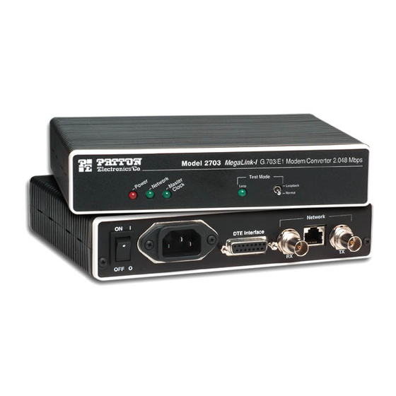
Summary of Contents for Patton electronics 2703
- Page 1 G.703/E1 Digital Modem SALES OFFICE Part# 07M2703-I Doc# 031041UI (301) 975-1000 Revised 08/16/99 TECHNICAL SUPPORT (301) 975-1007 An ISO-9001 http://www.patton.com Certified Company...
-
Page 2: Radio And Tv Interference
1.3 SERVICE Patton Electronics warrants all Model 2703 components to be free from defects, and will—at our option—repair or replace the prod- All warranty and nonwarranty repairs must be returned freight pre- uct should it fail within one year from the first date of shipment. paid and insured to Patton Electronics. - Page 3 Thank you for your purchase of this Patton Electronics product. The Model 2703 is equipped with two sets of eight DIP switches This product has been thoroughly inspected and tested and is warrant- (externally accessible), as well as seven jumpers (internal). These DIP ed for One Year parts and labor.
- Page 4 3.1.1 Switch Set S1 Switches S1-4 and S1-5: Rate Adaptation The configuration switches on S1 set clocking, rate adaptation, Set Switches S1-4 and S1-5 together to allow the Model 2703 to loopback enable, data invert, and interface (see also Switch S2). The adapt to terminal devices that run at data rates less than 2.048 Mbps default settings are summarized in table below.
-
Page 5: Internal Jumper Settings
Switch S1-8: Loopback Test Enable Depending upon the setting of switch S1-8 the Model 2703 will either be continually in loopback mode, or loopback mode will be enabled by pressing and holding the front panel switch. Since the front panel switch is spring loaded–it returns to “Normal” operation when pressure is released–this DIP switch provides a way of leaving the Model 2703 in “unattended”... - Page 6 The internal jumpers mounted on the Model 2703’s PC board Jumper LK2: 75 Ohm Receive Shield-to-Ground Connection (labeled LK1 - LK7) are used to configure the 75 ohm or 120 ohm net- work link parameters. Figure 4 (above) shows the location of the This setting determines whether the shield of the 75 Ohm (coax) Model 2703’s jumpers on the internal PC board.
-
Page 7: Power Supply Options
Jumper LK6 & LK7: 75 Ohm Termination Impedance Once the Model 2703 is properly configured, it is ready to connect This jumper sets the termination impedance correctly for 75 Ohm to your system. This section tells you how to properly connect the operation. -
Page 8: Led Status Indicators
4.2 CONNECTION TO THE TERMINAL DEVICE Once the Model 2703 is properly configured and installed, it The Model 2703 is wired as a DCE, and–when configured proper- should operate transparently. This sections describes power-up, read- ly–supports communication with a wide variety of terminal (DTE) ing the LED status monitors, and using the built-in loopback test devices. - Page 9 5.3 LOOPBACK TEST (LAL) PATTON MODEL 2703 SPECIFICATIONS The Model 2703 is equipped with a Local Analog Loopback (LAL) mode to assist in evaluating the operation of the local Model 2703. Any data sent to the local Model 2703 in this test mode will be echoed Network Interface: G.703 (returned) back to the user device.
- Page 10 PATTON MODEL 2703 PIN CONFIGURATIONS FACTORY PARTS AND ACCESSORIES C-1 Basic Standalone Units UNIVERSAL D-26 INTERFACE (DCE WIRING) The Patton Model 2703 standalone digital modem is available in three versions, depending upon the power supply installed. The Standard and Universal Interface versions are supplied with a power Not Used -26 13- (CTS/) Clear to Send cord, which must be specified in the model number when ordering .
- Page 11 SAFETY WARNINGS AND REQUIREMENTS FACTORY PARTS AND ACCESSORIES These warning notices apply to the Input Port, the port marked C-3 Terminal (DTE) Interface Cables “Network”. No terminal (DTE) cable is supplied with the Model 2703. You Warning: The port marked “SAFETY WARNING: see instructions may construct your own cable using the pin-out diagrams in Appendix for use”...


Need help?
Do you have a question about the 2703 and is the answer not in the manual?
Questions and answers