Table of Contents
Advertisement
Operator's
Manual
II:RRF rSMRN I
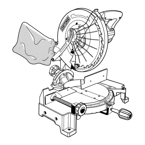
10 in. COMPOUND
MITER SAW
Double Insulated
Model No.
315.212040
o
O
_,
WARNING:
To reduce the risk of
injury, the user must read and under-
stand the operator's manual before
using this product.
Customer
Help Line: 1-800-932-3188
Sears, Roebuck
and Co., Hoffman
Estates,
IL 60179 USA
Visit the Craftsman web page: www.sears.com/craftsman
983000-471
2-04
Save this manual
for future
reference
0Q0s
Advertisement
Table of Contents

Related Manuals for Craftsman 315.212040


Summary of Contents for Craftsman 315.212040
- Page 1 Customer Help Line: 1-800-932-3188 Sears, Roebuck and Co., Hoffman Estates, IL 60179 USA 0Q0s Visit the Craftsman web page: www.sears.com/craftsman 983000-471 Save this manual for future reference 2-04...
- Page 2 • Warranty and Introduction ..............................• General Safety Rules ..............................• Specific Safety Rules ..............................• Symbols ..................................• Electrical ................................... • Glossary of Terms for Woodworking ..........................• Features ..................................10-12 • Unpacking and Tools Needed ............................• Loose Parts ..................................•...
- Page 3 • ALWAYS WEAR SAFETY GLASSES WITH SIDE WARNING: Read and understand all instruc- tions. Failure to follow all instructions listed below, SHIELDS. Everyday eyeglasses have only impact- may result in electric shock, fire and/or serious resistant lenses, they are NOT safety glasses. personal injury.
- Page 4 • NEVER USE IN AN EXPLOSIVE ATMOSPHERE. • NEVER TOUCH BLADE or other moving parts during use. Normal sparking of the motor could ignite fumes. • NEVER START A TOOL WHEN ANY ROTATING COM- • INSPECT TOOL CORDS PERIODICALLY. If damaged, PONENT IS IN CONTACT WITH THE WORKPIECE.
- Page 5 • NEVER cutmorethanonepiece at atime.DONOT occur, stand clear and allow the saw blade to come to STACK morethanoneworkpiece onthe sawtableat a a complete stop. Disconnect your saw from the power time. supply and securely retighten the blade bolt. • NEVER PERFORM ANYOPERATION F REEHAND, •...
-
Page 6: Symbols
Someof the following symbols maybe usedon thistool. Please studythemandlearntheirmeaning. P roper interpretation ofthesesymbols willallowyouto operate thetoolbetterandsafer. SYM BOL NAM E DESIG NATION/EXPLANATION Volts Voltage Amperes Current Hertz Frequency ( cycles persecond) Watt Power Minutes Time "%, Alternating Current Type of current Direct Current Type or a characteristic of current... - Page 7 The following signal words and meanings are intended to explain the levels of risk associated with this product. SYMBOL SIGNAL MEANING Indicates an imminently hazardous situation, which, if not avoided, will DANGER: result in death or serious injury. Indicates a potentially hazardous situation, which, if not avoided, could WARNING: result in death or serious injury.
-
Page 8: Double Insulation
DOUBLE INSULATION EXTENSION CORDS Double insulation is a concept in safety in electric power tools, When using a power tool at a considerable distance from which eliminates the need for the usual three-wire grounded a power source, be sure to use an extension cord that has power cord. - Page 9 Arbor Theshaftonwhicha bladeor cuttingtoolis mounted. The distance that the tip of the sawblade tooth is bent (or set) outward from the face of the blade. BevelCut A cuttingoperation madewiththebladeat anyangle Throw-Back otherthan90°to themitertable. Throwing of a workpiece in a manner similar to a kick- back.
- Page 10 Product Specifications: When the miter angle (miter table) is set at 0 ° and the bevel angle is set at 0°: Blade Diameter ......10 in. Maximum nominal lumber sizes: 4 x 4, 2 x 6 Blade Arbor ......5/8 in. When the miter angle (miter table) is set at 45 and the bevel No Load Speed .......
-
Page 11: Features
KNOW YOUR COMPOUND MITER SAW SPINDLE LOCK BUTTON See Figure 1. See Figure 3. Before attempting to use this product, familiarize your- A spindle lock button has been provided for locking the self with all operating features and safety requirements. spindle which keeps the blade in your saw from rotating. - Page 12 POSITIVE STOPS ON MITER TABLE Tighten all four bolts securely. Positive stops have been provided at 0,15,22-1/2, The hole pattern for mounting to a workbench is shown in 30, and 45 °.The 0,15,22-1/2,30 °,and 45 positive figure 5. Carefully check the workbench after mounting to stops have been provided on both the left and right side make sure that no movement can occur during use.
- Page 13 Thisproducthasbeen shipped completely a ssembled • Donotdiscard thepacking material u ntilyouhave except f ortheblade, m iterlockhandle, d ustbag,and carefully inspected andsatisfactorily operated thetool. dustguide. • Thesawisfactorysetforaccurate cutting. A fter • Carefully l ift sawfromthecartonbythecarrying handle assembling i t, checkfor accuracy. Ifshipping has andthesawbase, a ndplaceit ona level w orksurface.
- Page 14 Thefollowing itemsareincluded withyourCompound M iterSaw: • SawBlade-10in. • 5mmHexKey • MiterLockHandle • 8 mmHexKey • DustBag • 6 mmBlade Wrench • DustGuide • Operator'sManual SAW BLADE 6 mm BLADEWRENCH WORKCLAMP DUSTBAG DUSTGUIDE HEXKEYS(2) 5 mm, 8 mm _IITER LOCKHANDLE Fig. 7 WARNING: The use of attachments or accessories not listed might be hazardous and could cause serious per- sonal injury.
-
Page 15: Miter Lock Handle
DUST GUIDE WARNING: Do not connect to power supply until assembly is complete. Failure to comply could See Figure 9. result in accidental starting and possible serious To install the dust guide, place the end marked INSERT personal injury. over the exhaust port in the upper blade guard. Turn the guide so that the open end is facing down or toward the As mentioned previously, your saw has been factory as- rear of the saw. -
Page 16: Work Clamp
WORK CLAMP TO INSTALL BLADE See Figure 11, See Figures 12, 13, and 14. The work clamp provides greater control by clamping the WARNING: A 10 in. blade is the maximum blade workpiece to the fence or the saw table. It also prevents the capacity of your saw. -
Page 17: Adjustments
LOWER WARNING: If inner blade washer has been BLADE GUARD removed, replace it before placing blade on spindle. PHILLIPS SCREW Failure to do so could cause an accident since blade will not tighten properly. BLADE BOLTCOVER • Fit saw blade inside lower blade guard and onto spindle. -
Page 18: Squaring The Miter Table To The Fence
NOTE: M anyoftheillustrations i nthismanual showonly FENCE MITER TABLE portions of yourcompound mitersaw. T hisis intentional sothatwecanclearly showpointsbeingmadeintheil- lustrations. Neveroperateyoursawwithoutallguards securelyin placeandin goodoperatingcondition, SQUARING THE MITER TABLE TO THE FENCE See Figures 15- 18. • Unplug your saw. WARNING: Failure to unplug your saw could result FRAMING ZEROCLEARANCE in accidental starting causing possible serious... -
Page 19: Squaring The Saw Blade To The Fence
CUTTING A SLOT IN THE ZERO CLEARANCE FENCE THROAT PLATE BLADE In order to use your compound miter saw, you must cut a slot through the zero clearance throat plate to allow for blade clearance. To cut the slot, set your saw at 0 miter, turn saw on and allow the blade to reach full speed, then MITER carefully make a straight cut as far as it will go through... - Page 20 8 mm SCOKET SQUARING THE BLADE TO THE HEADSCREW(S) MITER TABLE See Figures 23 - 25. • Unplug your saw. WARNING: Failure to unplug your saw could result in accidental starting causing possible serious personal injury. • Pull the saw arm all the way down and engage the lock pin to hold the saw arm in transport position.
- Page 21 Yoursawhasthreescaleindicators, twooneithersideof BLADE the bevel s caleandoneonthe miterscale. A ftersquar- ingadjustments h avebeenmade, i t maybenecessary to loosen theindicators screws andreset t hemtozero. MITER COMBINATION TABLE SQUARE VIEW OFBLADENOT SQUARE WITH MITER TABLE,ADJUSTMENTS AREREQUIRED Fig. 25 CUTTING WITH YOUR COMPOUND MITER your WARNING:...
-
Page 22: To Crosscut With Your Miter Saw
TO CROSSCUT WITH YOUR MITER SAW • Before turning on the saw, perform a dry run of the cut- ting operation just to make sure that no problems will • Pull out the lock pin and lift saw arm to its full height. occur when the cut is made. - Page 23 TO BEVEL CUT WITH YOUR MITER • Pull out the lock pin and lift saw arm to its full height. BEVELCUT • Loosen the miter lock handle. Rotate the miter lock handle approximately one-half turn to the left to loosen. •...
-
Page 24: Compound Miter Cut
COMPOUND MITER CUT • Once the saw arm has been set at the desired angle, securely tighten the bevel lock knob. A compound miter cut is a cut made using a miter angle and a bevel angle at the same time. This type of cut is •... -
Page 25: Support Long Workpieces
• Slowly lower the blade into and through the work- piece. See Figure 29. • Release the switch trigger and allow the saw blade to stop rotating before raising the blade out of workpiece. Wait until the electric brake stops blade from turning before removing the workpiece from miter table. - Page 26 CUTTING COMPOUND MITERS To aid in making the correct settings, the compound angle setting chart below has been provided. Since compound cuts are the most difficult to accurately obtain, trial cuts should be made in scrap material, and much thought and planning made, prior to making your required cut.
-
Page 27: Cutting Crown Molding
CUTTING CROWN MOLDING When setting the bevel and miter angles for compound miters, remember that the settings are interdependent; Your compound miter saw does an excellent job of cutting changing one angle changes the other angle as well. crown molding. In general, compound miter saws do a better job of cutting crown molding than any other tool Keep in mind that the angles for crown moldings are very made. -
Page 28: Clamping Wide Workpieces
Bevel Angle Type of Cut Settin£ Left side, inside corner 1. Top edge of molding against fence 33.85 2. Miter table set right 31.62 3. Save left end of cut Right side, inside corner 1. Bottom edge of molding against fence 33.85 2. -
Page 29: Bevel Pivot Adjustment
BEVEL PIVOT ADJUSTMENT _i, WARNING:Before performing anyadjustment, make surethetoolis unplugged f romthepower • Your compound miter saw should bevel easily by loos- supplyandtheswitchis intheOFF( I) position. ening the bevel lock knob and tilting the saw arm to the Failure t o heed thiswarning couldresult i nserious left. -
Page 30: Depth Stop Adjustments
°EPT. STOP • Use a 5 mm hex key wrench to adjust the depth stop adjustment screw. The saw blade is lowered by turning A°J°ST.E.T BEVEL the screw counter-clockwise and raised by turning the screw clockwise. SCREW_ '_'/"_ LOCKKNOBMITE R •... -
Page 31: Brush Replacement
_k WARNING:When servicing, useonlyidentical Craftsman r eplacement parts.Useof anyotherpart t_.,,..,...,...,,._ BRUSH maycreate a hazard orcauseproduct d amage. WARNING: BRUSH Always wear safety goggles or safety glasses with side shields during power tool operation ASSEMBLY or when blowing dust. If operation is dusty, also wear a dust mask. - Page 32 CRAFTSMAN COMPOUND MINTER SAW - MODEL NUMBER 315.212040 NGURE 23--...
- Page 33 CRAFTSMAN COMPOUND MINTER SAW - MODEL NUMBER 315.212040 The mode, number ,A4H be found On a p,ate attached to the motor hous,ng. Ak_ays mention the mode, ] number in all correspondence regarding your Oompound Miter Saw or when ordering repair parts.
- Page 34 CRAFTSMAN COMPOUND MINTER SAW - MODEL NUMBER 315.212040 FmGURE B SEE NOTE "" NOTE : The assembly shown represents an important part of the double insulated system. To avoid the possibility of alteration or damage to the system, service should be performed by your nearest Sears Repair...
- Page 35 CRAFTSMAN COMPOUND MINTER SAW - MODEL NUMBER 315.212040 number in all correspondence regarding your Compound Miter Saw or when ordering repair parts. he model number will be found on a plate attached to the motor housing. Always mention the model 1...
- Page 36 CRAFTSMAN COMPOUND MINTER SAW - MODEL NUMBER 315.212040 FmGURE C ½...
- Page 37 CRAFTSMAN COMPOUND MINTER SAW - MODEL NUMBER 315.212040 number in all correspondence regarding your Compound Miter Saw or when ordering repair parts. he model number will be found on a plate attached to the motor housing. Always mention the model ]...
- Page 38 CRAFTSMAN COMPOUND MINTER SAW - MODEL NUMBER 315.212040 PARTS UST - FmGURE D 25 26 27...
- Page 39 CRAFTSMAN COMPOUND MITER SAW - MODEL NUMBER 315o212040 The model number wit! be found on a plate at ached to the motor housing. AMtays mention the mode number in all correspondence regarding your Compound Miter Saw or when ordering repair parts.
-
Page 40: Maintenance
Your Home For repair-in your home-of all major brand appliances, lawn and garden equipment, or heating and cooling systems, no matter who made it, no matter who sold it! ....For the replacement parts, accessories owner's manuals that you need to do-it-yourself....
Need help?
Do you have a question about the 315.212040 and is the answer not in the manual?
Questions and answers