Table of Contents
Advertisement
Available languages
Available languages
Quick Links
perator_s
nual
I:RRF rgMRN°
ZERO=TURN
RIDER
26 HP, 50" MOWER DECK
Model No. 247.25002
CAUTION:
Before
using this product,
read this manual
and follow
all safety
rules and operating
instructions.
,
SAFETY
,
ASSEMBLY
OPERATION
MAINTENANCE
PARTS LIST
o ESPANOL
Sears Brands
Management
Corporation,
Hoffman
Estates,
IL 60179, U.S.A.
Visit our website:
www.craftsman.com
FormNo.769-07727
(November 2 3,2011)
Advertisement
Table of Contents

Related Manuals for Craftsman 247.25002


Summary of Contents for Craftsman 247.25002
- Page 1 ASSEMBLY OPERATION MAINTENANCE PARTS LIST CAUTION: Before using this product, o ESPANOL read this manual and follow all safety rules and operating instructions. Sears Brands Management Corporation, Hoffman Estates, IL 60179, U.S.A. Visit our website: www.craftsman.com FormNo.769-07727 (November 2 3,2011)
- Page 2 (our testingprovesthat it will nothold a charge).A defectivebatterywill receivefree in-homereplacement. WARRANTYSERVICE Forwarrantycoveragedetails to obtainfree repairor replacement, c all 1-800-659-5917 or visitthe website: www.craftsman.com in all casesabove,if part repairor replacement i s impossible, t he ridingequipmentwill be replacedfreeof chargewith the sameor an equivalent model.
- Page 3 This machinewas builtto be operatedaccordingto the safeopera- This symbolpointsout importantsafetyinstructionswhich,if not tion practicesin this manual.As with anytype of powerequipment, followed,couldendangerthepersonalsafetyand/orpropertyof carelessnessor error on the partof the operatorcan resultin serious yourselfand others. Readand followall instructionsin this manual injury.This machineis capableof amputatingfingers,hands,toes beforeattemptingto operatethis machine.Failureto complywith and feet and throwingdebris.Failureto observethe followingsafety these instructionsmay resultin personalinjury.Whenyou seethis...
- Page 4 SLOPE OPERATION • Mufflerand engine becomehotand can causea burn.Do not touch. Slopesare a majorfactorrelatedto loss of controland tip-over • Checkoverheadclearancescarefullybeforedrivingunderlow accidentswhichcan result in severeinjuryor death.All slopes require hangingtree branches,wires,door openingsetc., wherethe extra caution.If youcannot back up the slopeor if youfeel uneasyon operatormay be struckor pulledfrom the machine,which could it, do not mowit.
- Page 5 CHILDREN SERVICE Tragicaccidentscanoccur ifthe operatoris notalert to the presence SafeHandlingof Gasoline: of children.Childrenare often attractedto the machineand the mowing Toavoidpersonalinjury or propertydamageuse extremecarein activity.They do notunderstandthe dangers.Neverassumethat handlinggasoline.Gasolineisextremelyflammableand the vaporsare childrenwill remainwhereyou last sawthem. explosive.Seriouspersonalinjury canoccur whengasolineis spilled • Keepchildrenout of the mowingareaand inwatchfulcare of a on yourselfor your clotheswhich can ignite.Washyourskin and responsibleadultotherthanthe operator.
- Page 6 bySears oranother qualified dealer. DO NOT MODIFY ENGINE • Checkthe blade(s)and engine mountingboltsat frequent Toavoid seriousinjuryor death,do notmodifyengine in anyway. intervalsfor propertightness.Also, visuallyinspectblade(s)for Tampering with the governorsettingcanlead to a runaway engineand damage(e.g.,excessivewear,bent,cracked). Replacethe cause it to operateat unsafespeeds.Nevertamper with factorysetting blade(s)with theoriginalequipmentmanufacturer's (O.E.M.) of enginegovernor.
- Page 7 SAFETY SYMBOLS This pagedepictsand describessafety symbolsthat may appearon this product. Read,understand,and follow all instructions on the machine beforeattemptingto assembleand operate. READTHE OPERATOR'S MANUAL(S) Read,understand,and followall instructionsin the manual(s)beforeattemptingto assembleand operate WARNING-- ROTATING BLADES Donot put handsor feet near rotatingpartsor underthe cuttingdeck.Contactwith the blade(s)can amputatehandsand feet.
- Page 8 15° Slope 15° Slope (OK) (TOO STEEP) '_. _ Figure 1 Figure 2 15° dashed line USETHISSLOPE GAUGE TODETERMINE IF A SLOPE IS TOOSTEEPFORSAFEOPERATION! To checkthe slope, proceedas follows: Removethis pageand fold along the dashedline. Locatea verticalobject on or behindthe slope (e.g. a pole, building,fence, tree, etc.) 3.
- Page 9 SET-UP Removethe two shoulderbolts and lock nuts in the seatpan as shown in Figure2. Moving The Riding mower Manually Yourriding mower'stransmissionisequippedwith a hydrostaticrelief valvefor occasionswhenit isnecessaryto movethe ridingmower manually.Openingthis valvepermitsthe fluid inthe transmissionto bypassitsnormalroute,allowingthe reartires to "freewheel." Toopen Seat Pan the hydrostaticreliefvalve,proceedas follows: Shoulder Locatethe hydrostaticbypassrod inthe rear of the ridingmower.
- Page 10 Position Drive Control levers Connecting the Battery Cables Thedrivecontrol leversof the ridingmowerare loweredfor shipping purposes.The flangelock nuts,hex screws,and flat washersthat Batteryposts,terminals,and relatedaccessoriescontainlead and normallysecurethe controllevers in their operatingpositionare lead compounds, c hemicalsknownto the Stateof California to cause unfastenedand installedin the slottedholesof the controlleversfor cancerand reproductive harm.
- Page 11 Lower Deck Discharge Chute Deflector Adjusting the Gauge Wheels Neveroperatethe mowerdeck withoutthe chutedeflectorinstalled Keephandsand feet awayfrom the dischargeopeningof the cutting deck. and in the downposition. Checkthe mowerdeck for a shippingbrace(withtag) that maybe NOTE: Thedeck gaugewheelsare an anti-scalpfeatureof the deck holdingthechute deflectorupwardfor shipment. If a braceis present, and are notdesignedto supportthe weightof the cuttingdeck.
- Page 12 Replace thefuel capand tightensecurely. W ipeup spilledfuel Adjusting the Seat beforestartingengine.If fuelis spilledDO NOTstartengine.Move Toadjustthe positionof the seat,pull up and holdthe seatadjustment ridingmowerawayfromareaof spillage. A voidcreatinganysource lever.Slidethe seat forwardor rearwardto the desiredposition;then of ignitionuntilfuelvaporsare gone. releasethe adjustmentlever.Makesureseat islockedintoposition Checking and Adding beforeoperatingthe riding mower.See Figure8.
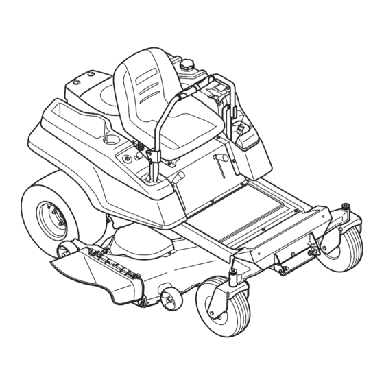
- Page 13 Deck Lift Deck Height Handle Parking Throttle/Choke Control -PTOSwitch LH Drive RH Drive nition Switch Hour Meter/ Control Lever Control Lever indicator Panel SeatAdjustmentLever Cup Holder FuelTankCap Storage Tray Figure11 STORAGE TRAY Nowthat youhaveset up yourridingmower,it'simportant to become acquainted with itscontrolsand features.Referto Figure11. The storagetray islocatedat the rearof the RHconsole.
- Page 14 iGNiTiON SWITCH HOUR METER/INDICATOR PANEL Theignition switchis locatedon the RH consoleto the rightof the RUN_ Thehourmeter/indicator panel i s located on the operator'sseat.Theignitionswitch LHconsole totheIdt oftheoperator's s eat. hasthree positions. Hour Meter Features STOP_ -- Theengine and electri- The hourmeterrecords the hoursthat the cal systemis turnedoff.
- Page 15 THROTTLE/CHOKE CONTROL GENERAL SAFETY Thethrottle/choke controlis locatedon the LHconsoleto • RECEIVEINSTRUCTION -- Entirelyreadthis operator'smanual. theleft of theoperator'sseat.Whenset in a givenposition,a Learnto operatethis machineSAFELY. D o not risk INJURYor uniformenginespeedwill be maintained. DEATH. A llowonlythose who havebecomecompetentin its Pushthe throttle/choke controlhandleforwardto increase usageto operatethis ridingmower.
- Page 16 BEFORE OPERATING YOUR RiDiNG MOWER STARTING THE ENGINE • Beforeyou operatethe ridingmower,studythis manualcarefully to familiarizeyourselfwith the operationof all the instruments and This riding moweris equippedwith a safetyinterlocksystemdesignee controls.It has been preparedto help youoperateand maintain for the protectionof the operator.Donotoperatethe ridingmowerif yourriding mowerefficiently.
- Page 17 Cold Weather Starting DRIVING THE RIDING MOWER When s tarting the engine attemperatures near o rbelow f reezing, ensure the correct viscosity motor oilisused i nthe engine and the Avoidsuddenstarts,excessivespeedand suddenstops, battery isfully charged. Start the engine asfollows: Adjustthe operator'sseat to the mostcomfortablepositionthat 1.
- Page 18 Driving the Riding mower Forward Turning the Riding mower While Driving Forward Keepall movement o f the drivecontrol leversslowand smooth. Whenreversingthe directionof travel,we recommendperforming Abrupt movement o f the controlleverscan affectthe stabilityof the gradual'U' turns wherepossible.Sharperturns increasethe possibil- riding mowerand couldcause the ridingmowerto flip over,which ity of turf defacement,and couldaffect controlof the riding mower.
- Page 19 4. To execute azero turn move t he turn side drive control lever to Turning While Driving Rearward the inward neutral position, while m oving the other control lever Toturn the riding mowerwhiledrivingrearward,movethe control forward. leversas necessaryso that one leverisforwardof the other.The NOTE: Making azero turn ongrass w ill g reatly increase the potential ridingmowerwill turnin thedirectionof the forwardcontrollever.
- Page 20 Pushthe PTOswitchdownwardto the DISENGAGED position. Executing a Zero Turn Usethe deck lift handleto raisethe deck to itshighestposition. If dismounting the ridingmower,movethe drivecontrolleversfully When executinga zeroturn, the ridingmowerMUSTBE STOPPED. outwardin theneutralposition,engagethe parkingbrakeO, move Executinga zeroturn whilethe ridingmoweris movingcan signifi- the throttle/choke controlleverto the FAST_ position,turnthe cantly reduceyourcontrolof the ridingmowerand will causesevere ignition s witchto STOP_ and remove the keyfromthe switch.
- Page 21 USING THE MOWER DECK CHECKING SAFETY iNTERLOCK CiRCUiTS Periodically checkthe safetyinterlockcircuitsto ensuretheyare workingproperly.If a safetycircuitis notworkingas designed,call l Makecertainthe area to be mowedisfree of debris,sticks, stones, 1-800-659-5917 to scheduleridingmowerinspectionservicefrom wireor other objectsthat can be thrownby the rotatingblades. Sears Parts& Repair.DO NOToperatethe ridingmowerif any safety NOTE: Donot engagethe mowerdeck whenloweredin grass.
- Page 22 MAINTENANCE SCHEDULE Followthe maintenance schedulegivenbelow.This chart describes serviceguidelinesonly. Use theService Log columnto keeptrack Beforeperforminganytype of maintenance/service, disengageall of completedmaintenance tasks.To schedule service from Sears controlsand stop the engine.Wait untilall movingparts havecome Parts& Repair,call 1-800-659-5917,, to a completestop. Disconnectsparkplug wireand groundit against theengineto preventunintendedstarting.Alwayswearsafetyglasses duringoperationor while performing any adjustments or repairs.
- Page 23 Draining the Oil Runthe enginefor a short time to warmthe engineoil. The oil Beforeperformingany maintenance or repairs,disengagethe PTO, will flow morefreelyand carry away moreimpurities. Usecare to movethe drivecontrolleversfully outwardin the neutralposition, avoidburnsfrom hotoil. engagethe parkingbrake,stop theengineand removethe key to Locate theoil drainvalveon theleft sideof theengine. S ee Figure 22. preventunintendedstarting.
- Page 24 Placethe newfilter in an open panwith the open sidefacing up. Spark Plug Fillwith newoil untilthe oil reachedthe bottomof the threads. Waittwo minutesforthe oil to be absorbedby the filter material. DONOTcheckfor a sparkwith the sparkplug removed.DONOT Applya thinfilm of cleanoil to the rubbergasketon the filter. crank the enginewith the sparkplug removed.
- Page 25 Measurethe plug gap with a feelergauge.Correctas necessary To Drain the Fuel: by bendingthe side electrode,Figure26. Thegap shouldbe set Locatethe fuel filter,which is routedon the right sideof the to .02-.03inches(0.60-0.80ram). engine betweenthe fueltank and the engine.See Figure27. Electrode Clamps_ .030 in. (0.76 ram) Figure27 Figure26...
- Page 26 LUBRiCATiON BATTERY REMOVAL Usinga pressurelubricating gun, lubricate t he front castorwheel axles andthe front pivot axlewith No.2 multipurposelithium greaseafter every 10 hoursof service. leadcompounds.Washhandsafter handling. Periodicallylubricateall otherpivotpointswith a quality lubricat- ingoil. The batteryis locatedon the right/rearof the riding mowerbeneaththe seat box frame.To removethe battery: GENERAL BATTERY iNFORMATiON...
- Page 27 Pullback the lock collarof the nozzleadapterand pushthe Charging the Battery adapterontothedeck wash nozzleat the left end of the mower Testand,if necessary,rechargethebatteryafter the riding deck. Releasethe lock collarto lock the adapteron the nozzle. mowerhasbeen storedfor a periodof time. Referto Figure30. A voltmeteror load testershouldread 12.6volts(DC) or higher acrossthebatteryterminals,See Figure29, Voltmeter Stateof...
- Page 28 USING THE TRANSMiSSiON BYPASS RODS forwardor rearwardwithinthe rangeof the slot in eachcontrol lever mountingbracket. If for any reasonthe ridingmowerwillnot driveor youwish to movethe Toadjust thedrive controlleverheight,proceedas follows: riding mower,the two hydrostatictransmissions are equippedwith a bypassrodthat will allowyou to manuallymovethe riding mowershort Removethe flangelock nut, flat washer,and hexscrewsecuring distances.
- Page 29 Front to Back Leveling Leveling the Mower Deck Whencorrectlyadjustedthe mowerdeck shouldbe level sideto side, The front of thedeck shouldbe approximately 1/4"lowerthan the and the frontof the deck shouldbe approximately 1/4inchlowerthan rearof the deck.Adjust if necessaryas follows: the rearof deck. With the deck raisedoff of the ground,rotatetheouterbladesso NOTE:Checkthe riding mower'stire pressurebeforeperforming any that they are parallelto the frameof the ridingmower.
- Page 30 DECK REMOVAL Adjusting the Gauge Wheels Removethe mowerdeck fromthe riding moweras follows: Movethe ridingmowerto a levelsurface,disengagethe PTO, Keephandsandfeetawayfromthedischarge opening ofthecutting deck. stop the engine,and set the parkingbrake. NOTE:The deck gaugewheelsare an anti-scalpfeatureof the deck Movethedeck gaugewheelsor rollersto their highestsetting and are not designedto supportthe weightof the cuttingdeck. (lowestdeck setting).
- Page 31 c. Pull the left s ide ofthebelt r earward and downward while Slidethe deck forwardsothat the deck front hangerrod can be manually turning the PTO pulley tothe right u ntil the belt liftedout of the two slotsof the front deck bracket.After lifting the rides o ut o nto the edge o fthe lower sheave ofthe pulley.
- Page 32 b. Make c ertain thebelt i sinthe spindle pulleys ofthe deck, Mower Blade Care and that t he backside ofthe belt i sagainst both the fixed and movable idler p ulleys. Refer toFigure 34. c. Sitting behind theriding m ower, facing f orward, make c ertain Beforeperforming anymaintenance, p lacethe PTOswitchin the"OFF"...
- Page 33 TRANSMiSSiON DRIVE BELT RIDING MOWER HIGH SPEED TRACKING Severalcomponents must be removedand specialtools usedin If the riding mowertracks to one sidewith bothdrivecontrollevers orderto changethe riding mower'stransmissiondrivebelt. See your fully forward,adjust thecontrol leversas follows: SearsServiceCenteror to scheduleservice,simplycontactSearsat Checkfor properand balancedair pressurein bothfrontand rear 1-800-4-MY-HOME®.
- Page 34 Neverstoregardenriding mowerwith fuel in tank indoorsor in poorly ventilatedareaswherefuel fumesmay reachan openflame,spark, or pilot lightas on a furnace,water heater,clothesdryer,or gas app ance. RIDING MOWER STORAGE Sharpenthe bladesso that the mowerwill be readyto use when needed. If yourriding moweris notgoing to be operatedfor an extendedperiod Protectthe metalsurfaces.Repairscratcheswith the appropriate of time (thirtydays to approximately six months),the ridingmower touch-upspraypaint.
- Page 35 Beforeperforming anytypeof maintenance/service, disengage all controls and stoptheengine.Waituntilall moving partshavecometo a complete stop.Disconnect sparkplugwireandgrounditagainstthe I engine to prevent u nintended starting. A lways wearsafety glassesduring l operation or whileperforming anyadjustments o r repairs. Thissectionaddresses minor service issues.To locate the nearest Sears Service Centeror to scheduleservice,simplycontactSears at 1-800-4-MY-HOME®.
- Page 36 Engineoverheats Engineoil levellow Fillenginewith properamountand type of oil. Air flow restricted Cleangrass clippingsand debrisfrom aroundthe engine'scoolingfins and blowerhousing. Enginehesitatesat high RPMs 1. Sparkpluggap settoo close Removesparkplug and adjustgap. Engineidles poorly Fouledspark plug Replacesparkplug and adjustgap. Dirtyair cleaner Cleanor replaceair cleanerelementand/orclean pre-cbaner.
- Page 37 Craftsman Zero=Turn Rider B IViodel No. 247.25002 703-08734- SeatBracket 0637 710-04482 Hex FlangeBolt, 3/8-16x ,875 710-04484 HexWasherScrew,5/16-18x ,750 712-04063 FlangeLockNut,5/16-18 732-04849 Compression Spring,1,50x 3,90 x ,200 732-04563 Compression Spring,,68x 1,065x .055 736-0258 Flat Washer,,385x 1,0x ,135 938-0296 ShoulderScrew,,437x .268x 5/16-18...
- Page 38 Craftsman Zero=Turn Rider B Model No. 247.25002 935-0149 FuelTankBushing 735-04081 i RubberGrommet 951-04209B FuelTank 751-10442 FuelPick-UpFitting 951-12428 i FuelCap 751-12118 FuelRolloverValve 751-12089 VentHose...
- Page 39 Craftsman Zero=Turn Rider- IViodel No. 247.25002 15.. ,\\\...
- Page 40 Craftsman Zero=Turn Rider B Model No. 247.25002 603-04680A- 0637 Frame Assembly 703-05829 Drive Idler Arm 710-05097 Hex Screw, 3/8-16 x 1.5 710-3005 Hex Screw, 3/8-16 x 1.25 712-04065 Flange Nut, 3/8-16 732-0626 Extension Spring, .75 x 5.06 710-0520 Hex Screw, 3/8-16 x 1.5...
- Page 41 Craftsman Zero=Turn Rider B Model No. 247.25002 18_<_...
- Page 42 Craftsman Zero=Turn Rider B Model No. 247.25002 603-04162 RH ExhaustAssembly 603-04163 LH ExhaustAssembly 603-04691- 0637 FrameAssembly 703-05441A MufflerMountBracket 710-0227 HexWasherScrew,#8-18x 0.500 710-04683 HexWasherScrew,3/8-16x 1.000 710-0599 HexWasherScrew,1/4-20x 0.500 710-1017 i AB Screw,1/4-14x 0.625 710-3008 Hex Screw,5/16-18x .75 710-3217 MachineScrew,#8-32 x 0.375...
- Page 43 Craftsman Zero=Turn Rider B Model No. 247.25002 °\15...
- Page 44 Craftsman Zero=Turn Rider B Model No. 247.25002 603-04564 ConsoleMountBracket 603-04946- SeatFrame 0637 735-04082C Foot Pad 703-05373B Foot Rest 736-0148 LockWasher,3/8 703-06451 ConsoleMountBracket 703-06623- 0637 FuelTankSupportBracket 710-04484 HexWasherScrew,5/16-18x .750 726-0201 SpeedNut, .3125 710-0604A i HexWasherScrew,5/16-18x .825 710-0778 HexWasherScrew,1/4-20x 1.500 710-0895 HexWasherScrew,1/4-15 x .750 710-3008 Hex Screw,5/16-18x .75...
- Page 45 Craftsman Zero=Turn Rider- IViodel No. 247.25002 20/_- ......51 20 /...
- Page 46 Craftsman Zero=Turn Rider B IViodel No. 247.25002 603-04160C- 914-04023 Cotter Pin 0637 DeckLift ShaftAssembly 716-0106 E-Ring,.625 Dia. 603-04322- 720-0311 HandleGrip 0637 LapbarLeverRH 723-04080 RodEnd 603-04324- 0637 LapbarLeverLH 727-04141 DamperCylinder 731-04735 947-04065 BrakeRod(42"& 50" Decks) HandleGrip 647-04099A ControlShaft 731-05732 Spacer,.62x 1.0...
- Page 47 Craftsman Zero=Turn Rider B IViodel No. 247.25002...
- Page 48 Craftsman Zero=TurnRider B Model No. 247.25002 918-04317 WheelHub,7/16-14x 1.6 918-04431B Transmission Assembly,LH 918-04432B Transmission Assembly,RH 634-04128 WheelAssembly,18x 9.5-8 710-0176 i Hex CapScrew,5/16-18x 2.75 710-0395 i Hex CapScrew,5/16-18x 2.25 710-3119 i Hex CapScrew,3/8-16x .75 712-04063 i Hex FlangeNut,5/16-18 712-0459 i Hex FlangeNut,7/16-20...
- Page 49 Craftsman Zero=Turn Rider B Model No. 247.25002 _/51 i2o.
- Page 50 Craftsman Zero=Turn Rider B Model No. 247.25002 903-04328B- 736-0407 BellWasher,.45x 1.0x .062 4044 DeckHousing 736-0225 InternalToothLockWasher,5/8 918-04125B SpindleAssembly 736-3072 FiatWasher,.38x .93x .110 631-04070A DischargeChuteAssembly 737-04003D DeckWashNozzle 683-0254B- 738-04162A ShoulderSpacer,.884x .190 4044 DeckHangerBracket 938-3056 ShoulderScrew,.5 x 2.5 x 3/8-16 703-05825C- IdlerArm 942-04053C Blade,2 in 1, 17.9...
- Page 51 Craftsman Zero=Turn Rider- IViodel No. 247.25002 731-05500 FlangeBearing,1.0x 1.246 603-04385A- FrontPivotAxle 4044 936-0169 LockWasher,3/8 i603-04370- CastorWheelBracket 936-0227 FlatWasher,.39x 1.5x .134 4044 FiatWasher,1.0x 1.75x .107 736-0250 634-04321A- WheelAssembly,11x 4 x 5 937-3000 0961 LubeFitting,3/16 710-04186 Hex Lock Screw,1/2-13x 1.25 710-04652 i Bolt, 1/2-20x 7.25...
- Page 52 Briggs & Stratton Engine Model 445677-0955-G5 For Zero=Turn Rider Model No. 247.25001 1027 1013 \,, /j ..552A_ 742 d_9 616 742 C_I_ 552A 691 @ 750 _ 220 _L_i_:_...
- Page 53 Briggs & Stratton Engine Model 445677-0955-G5 For Zero=Turn Rider Model No. 247.25001 27 <> ':-_-:_ 75 %_::_ 146(_ " 50 [ 1777¸¸¸17777777777777771 ::@/'- < 929 _ 1_:: ,t:...
- Page 54 Briggs & Stratton Engine IViodel 445677=0955-G5 For Zero=Turn Rider IViodel No. 247.25001 918 i 1O22 1022 1026 _._. "_._ 1026A "'_. 1o22 1lOO _®'...
- Page 55 Briggs & Stratton Engine Model 445677=0955=G5 For Zero=Turn Rider Model No. 247.25001 163 _.._- .., ..k.,,\-/( ] "7 :: o'_c--j ;;;;;;_ ,y?_/ ..\ '.. k id' 9 231 9 105 ;I' " 118A [ 633 @ 217 _l! I 1126...
- Page 56 Briggs & Stratton Engine Model 445677=0955=G5 For Zero=Turn Rider Model No. 247.25001 186A_ 186B _ 9_8A ... /// __-: :: ... -. _/ 964 (,_ 306A...
- Page 57 Briggs & Stratton Engine Model 445677-0955-G5 For Zero=Turn Rider Model No. 247.25001 ' "N 1070 1005 1119 332 f_ 75 (_ >) _, × <_ //_! I"=_; 697_ .._ 1012 _ l L:L:::-::::::: :: / 1054 "'_ "%_\ 209_,_<_...
- Page 58 Briggs & Stratton Engine Model 445677-0955-G5 For Zero=Turn Rider Model No. 247.25001 121 CARBURETOR OVERHAUL _i_=_ _ _7:_ P_=_ 163 i>f <:_ ,,_ "_>i k_\........... r... 7 ....276 d*_' 672 k,,<,./_ ::;/ 276A _::<'# 4;,_ ,,:_jj 137f ....1124 f,,,,,J_:--_ %,,,/"...
- Page 59 Briggs & Stratton Engine IViodel 445677=0955=G5 For Zero=Turn Rider IViodel No. 247.25001 793564 rlinder A ssembly 699721 Kit-IdleSpeed 797673 Bushing/SealKit(MagnetoSide) i104 694918 Pin-FloatHinge 391086s Seal-Oil(MagnetoSide) 797410 Valve-FloatNeedle 796307 Sump-Engine 699723 Valve-Choke 799088 Head-Cylinder(Cylinder1) 792296 Jet-Main(Standard)(Left Jet) 799089 Head-Cylinder(Cylinder2) 117A 1842627 Jet-Main(Standard)(Right Jet) 693997 Gasket-Cylinder H ead...
- Page 60 Briggs & Stratton Engine IViodel 445677=0955=G5 For Zero=Turn Rider IViodel No. 247.25001 695410 Washer-Sealing 697891 SeaI-ORing(IntakeManifold)(Red) i278 792651 Washer(GovernorControlLever) 699813 Seal-Choke/Throttle Shaft(ChokeShaft) i287 691108 Screw(DipstickTube) 66538s Boot-Spark Plug i304 799955 Housing-Blower 690958 Nut(Carburetor) i305 691005 Screw(BIowerHousing)(1/4-20x.68) 691215 Spacer(RotatingScreen) i305A 698336 Screw(BlowerHousing) 668A 691500 Spacer(RotatingScreen)
- Page 61 Briggs & Stratton Engine IViodel 445677=0955=G5 For Zero=Turn Rider IViodel No. 247.25001 499600 Cover-Rocker ( Cylinder#2) 1024 796220 Pump-Oil 1026 690981 Rod-Push(Steel)(Exhaust) 1026A 690982 Rod-Push(Aluminum)(Intake) 1027 795890 Filter-Oil 1029 690972 Arm-Rocker Label-Emissions (Availablefrom a Briggs& 1036 StrattonAuthorizedDealer) 1054 280275 Tie-Cable 1058 278776TRI 1059 698516 Kit-Screw/Washer ( Alternator)
- Page 62 Craftsman Zero=Turn Rider IViodel 247.25002 777D18808 777122282 777D18807 777D18808 777S34190 777S33084 777122885 777122973 777123134 777S33184 777D18810 777S30503 777X44930 (On units produced on or before Dec. 31,2011) MTD CONSUMER GROUP I NC. I[ This equipment meets U .S. E PA EVP 777D15548 for2011model y ear.
- Page 63 This page intentionally left blank. Use this page to make any notes regarding your tractor.
- Page 64 Congratulations on making a smart purchase. Your new Craftsman® product is designed manufactured for years of dependable operation. But like all products, it may require repair from time to time. That's when having a Repair Protection Agreement can save you money and aggravation.
- Page 65 Look For Relevant Emissions Durability Period and Air index information On Your Engine Emissions Label Engines that are certified to meet the California Air Resources Board (CARB) Tier 2 Emission Standards must display information regarding the Emissions Durability Period and the Air Index. Sears Brands Management Corporation makes this information available to the consumer on our emission...
- Page 66 (Thispage applicablein the U.S.A.and Canadaonly.) Sears Brands Management Corporation (Sears), the California Air Resources Board (CARD) and the United States Environmental Protection Agency (U.S. EPA) Emission Control System Warranty Statement (Owner's Defect Warranty Rights and Obligations) EMISSIONCONTROL WARRANTY COVERAGEISAPPLICABLE TO CERTI- YEAR 1997AND LATERENGINES WHICHARE PURCHASED AND USED FIEDENGINESPURCHASEDIN CALIFORNIAIN 1995ANDTHEREAF- ELSEWHERE IN THE UNITEDSTATES (ANDAFTERJANUARY1,2001 IN...
- Page 67 FEDERAL and/or CALIFORNIA EMISSION CONTROL WARRANTY STATEMENT YOUR WARRANTY RIGHTS AND OBLIGATIONS MTDConsumerGroupInc,the United StatesEnvironmental P rotectionAgency (EPA),and, forthose productscertifiedfor sale in the stateof California,the CaliforniaAir ResourcesBoard(CARB)are pleasedto explainthe emission(evaporativeand/or exhaust)controlsystem(ECS) warrantyon youroutdoor 2006 andlater smalloff-roadspark-ignitedengine andequipment(outdoorequipmentengine)In California,new outdoorequipmentengines mustbe designed,built and equippedto meetthe State'sstringentanti-smogstandards (in otherstates, 1997andlater modelyear equipmentmustbe designed,built, and equippedto meet the U.S.
- Page 68 WARRANTED PARTS: The repairor replacementof any warrantedpart otherwiseeligiblefor warrantycoveragemay be excludedfrom such warrantycoverageif MTDConsumerGroup Inc demonstratesthatthe outdoor equipmentengine has beenabused,neglected,or improperlymaintained,and that suchabuse, neglect,or impropermainte- nancewasthe direct causeof the needfor repairor replacementof the part. That notwithstanding, a ny adjustmentof a component t hat hasa factory installed, andproperlyoperating,adjustmentlimitingdevice is still eligible for warrantycoverage.
- Page 69 Cubierta posterior Servicio y Mantenimiento ..Paginas 89-101 CRAFTSMAN GARANTiA TOTAL Durante tresaSosdesdela fechade cornpra, t odaslaspartesno fungible de esteequipode equitaci6n est_.n garantizados c ontracualquier d efecto de rnateriales o rnano de obra.Undefectono fungibleparticipantes r ecibir&n g ratisen la casala reparaci6n o sustituci6n si la reparaci6n es irnposible.
- Page 70 Estarn_.quina fuedise_ada paraserutilizada de acuerdo conlaspr_.cticas Estesirnboloindicainstrucciones de seguridadirnportantes que,de de operaci6n segura de estemanual. A Iigualqueconcualquier t ipode noobservarse, p odriaponeren peligrola seguridad personal y / o la equipo rnotorizado, o errorpotpartedel operario puede causar lesiones propiedad del rnisrno ya losdern_.s. L eay sigatodaslasinstrucciones graves.
- Page 71 PENDIENTE DE LA OPERACI6N • Desconectarla hoja (s), frenode estacionarniento establecidos, apagueel motory esperarhastaque la hoja (s) Ilegara una Laspendientes son unfactorirnportante relacionado con la p_rdidade paradacornpletaantesde retirarde c_sped,vaciar los recortes, controly un accidentede vuelco,quepuederesultaren lesionesgraves destaparel canal, retirarrestosde cespedo desechos,o hacer o la rnuerte.Todaslaspistasrequieren rnuchaprecauci6n.
- Page 72 N QOS SERVIClO Puedenocurriraccidentestr_.gicos si el operadorno est,. atentoa El manejoseguro de la gasolina: la presenciade los niSos.LosniSosson a rnenudo atraidos por la Paraevitarlesionespersonaleso daSosrnaterialesde uso extrerno rn_.quina y la actividadde siega.EIIosno entiendenlos peligros. cuidadoal rnanipular la gasolina.La gasolinaes altarnente inflarnable Nuncaasurnaque los niSosperrnanecer_.n e n la Qltirna vez que los vi.
- Page 73 • Reviseperi6dicarnente para asegurarse de que las cuchillas • Mantener o reernplazar l as etiquetasde seguridade instruc- se detenganpor cornpletoa un plazoaproxirnado de cinco clones,seg[3n seanecesario. (5) segundosdespu_sde que realiceel controlde la retirada • Observarlas leyesy los reglarnentos adecuadosde elirninaci6n de la hoja.Si las cuchillasno sedetienenen el marcode este de gas, petr61eo, etc, paraprotegerel medic arnbiente.
- Page 74 SilVIBOLOS DE SEGURIDAD Esta p&ginarepresenta y describela seguridadlos simbolosque puedenpareceren este producto.Lea,comprenda,y sigatodas instrucciones en la m_quinaantesprocurarpara reuniry operar. LEA EL MANUAL(S) DEL OPERADOR leido, entienda, y siga todas las instrucciones en el manual(s) antes de procurar montar y funcionar PELIGRO-- DE EL CORTE DE PIE Guarde manos y pies lejos de hacer girar partes.
- Page 75 15° Pendiente 15° Pendiente (ACEPTAR) (DEMASlADO ESCARPADO) Figura1 Figura2 15°1f n USODE ESTEPENDIENTE DECALIBREPARADETERIVIINAR SI UNAPENDiENTE ESDEMASiAD0ESCARPAD0 PARAUNA0PERACIONSEGURN Para comprobar lapendiente,hagaIo siguiente: Borraresta p_.gina y doble a Io largo de la linea discontinua. Localizarun objeto vertical sobre o detr_sde la pendiente(un poste, un edificio, unavalla, un _.rbol,etc.) 3.
- Page 76 CONFIGURACION Instalar el asiento del operador Mover el tractor rnanualmente Parainstalarel asientode precederde la siguiente: NOTA:El asientovienecon el interrupter del asientoy el asiento La transmisi6nde sutractorestAequipadocon una vAIvulade alivio adjunto. hidrost_ticaparalas ocasionescuandoes necesarioparamover Cortar todaslas correasque sujetanel conjuntodel asientoy la el tractorde formamanual.".
- Page 77 Instalaci6n del cable de la baterias Coloque las palancas de control de la transmis= posici6n. i6n en Las palancasde control de la transmisi6n del tractorse bajanpara el Lospostesde la bateria,terminalesy accesoriosrelacionados embarque.Lastuercasde seguridadcon brida,lostornilloshexago- contienenplomoy compuestos quimicos,conocidospor el Estadode nalesy las arandeJas planasque normalmente fijanlas palancasde Californiaque causanc_.ncer y da_osen la reproducci6n.L_.vese las controlen su posici6noperativase aflojane instalan en los orificios _manos despu_sde a manpu ac 6n.
- Page 78 Bajo la cubierta del canal de descarga del deflector Ajuste de las ruedas de calibraci6n No utilicenuncala cubierta de la cortadorasinel deflectordel canal Mantenga las manosy piesde distanciade la aberturade descarga instalado y en posici6nbaja. de la plataformade corte. NOTA: Las ruedasde calibraci6nla cubiertason una funci6nanti- Compruebela plataformade corte para unatraba de seguridad(con cuerode la cubierta y no est_.ndise_adospara soportarel pesode la etiqueta),que puedeser la celebraci6n el deflectorhaciaarriba para...
- Page 79 derrarnesde combustible antesde arrancarel motor.Si sederrarna combustible NOarranque el motor.Mueva tractorfueradel Areade derrarne.Evitarla creaci6n de cualquier f uentede ignici6nhasta que losvaporesde combustible se banido. El control y la adici6n de aceite Sutractorseenviacon aceiteen el motor.Sin embargo, d ebecornpro- Cornpruebesiernpreel nivelde aceiteantesde cadauso cornose indicaen la secci6nServicioy Mantenirniento.
- Page 80 Posicionamiento Manija de la altura de la elevaci6n plataforma la plataforma Del acelerador Qstran( Interrupter de .potencia de arranque Palancade Palancade Interrupter de Medidor horario/ controlde controlde encendido Panel indicador transmisi6n transmisi6n izquierda derecha Palanca de ajuste del asiento Tap6ndel tanque de combustible Bandeja almacenamiento...
- Page 81 PALANCAS DE CONTROL DE TRANSMISI6N LADO DERECHO Y LADO IZQUIERDO Nuncaremolquede sutractor.Remolque del tractorcon lasruedas Las palancasde control del LADODERECHO y del LADOIZQUI- traserasen el suelopuedecausargravesdaSosalas transrnisiones. ERDOse encuentran a cada ladodel asientodel operador.Estas PALANCA DE AJUSTE DEL ASIENTO palancasabisagradasgiran haciaafuera,haciael espacioabierto, para perrnitiral operadorsentarseen el asientodel tractoro de- La palancade ajustedel asientoest&ubicadadebajodel asiento, scenderdel rnisrno.Las palancasdebenestar totalrnenteabiertasy en...
- Page 82 PALANCA DE ENGANCHE DEL FRENO DE Caracteristicas del panel indicador Indicadorde bateria MANO Se enciendey el voltajede la bateriase rnuestrabrevernente cuando La palancade enganchedel frenode rnanoest,. ubicada el interruptor de encendidosegira a la posici6nRUN_. haciaadelante/ala izquierdadel marcodel asiento,y se la Enciendepara indicarel voltajede la bateriaha caido por debajo usa para colocarel freno de rnano.
- Page 83 • Eviteoperaren superficiesde tracci6ninestables;tengaextrema mane,el sistemade bloqueode seguridadapagael motor. precauci6nsi la superflciees resbaladiza. • Si el operadorabandonasu asientocon la potenciade arranque • Reduzcala velocidadantesde girar y det_ngase completamente (PTO)enganchada,seencuentreo no colocadoel frenode en cualquiermaniobrade giro cero. mane,el sistemade bloqueode seguridadapagael motor. •...
- Page 84 DETENCION DEL MOTOR Girela Ilavede encendidoen el sentidode lasagujasdel reloja la posici6nSTART _ y su_ltela cuandoarranqueel motor;sinem- Coloqueel interruptorde la PTOen la posici6nOFR bargo,no d_ arranque continuarnente d urantern_.s de 5 segundos Muevael RH y LHpalancasde controlde accionarniento por vez.Si el motorno arrancaen este per[odo, g ire la Ilavea la totalrnentehaciaafueraen la posici6nneutral.
- Page 85 NOTA: Silaspalancas decontrol nisiquiera est_.n enlaposM6n Giro con el tractor en marcha directa neutral, serefieren alservMo ymantenimiento para o btener instruc- ciones para ajustar laspalancas para que sean a Qn, AI invertirla direcci6ndel recorrido,le recomendamos queen Io 4, Mueva elacelerador / cebadorde controlhada adelantecon el posiblerealicegiros gradualesen "U".Losgirosm_.sagudosaumen- FAST_...
- Page 86 Cuantomayorseala distanciade adelantehaciaatr_.sentrelas Realizar un giro mientras se conduce marcha arras dos palancas,m_.scerradoser_. e l giro que dar_.el tractor. Toturn the tractorwhile drivingrearward,movethecontrol leversas necessaryso that one leveris forwardof the other.The tractorwillturn Para realizarun "girode pivote',muevala palancade controldel in the directionof the forwardcontrol lever. lado de giro a la posici6nneutral,mientrasmuevela otra palanca de control haciaadelante, Paragirar a la izquierdamientrasse desplazamarchaatr_.s,...
- Page 87 DETENCION DEL TRACTOR Giro de radio cero Muevalas dos palancasde controlhastala posici6nde punto rnuertoparadetenerel rnovirniento del tractor. Pararealizarun giro de radiocero,el tractorSE DEBEDETENER.La Presioneel interruptorde la tornade fuerzaa la bajaa la posici6n realizaci6n de un girode radiocerocon el tractoren movirniento puede de desenganche.
- Page 88 USO DE LA PLATAFORiVlA DE LA CORTADORA CONTROL DE LOS CIRCUITOS DE BLOQUEO DE SEGURIDAD Reviseperi6dicarnente los circuitosde enclavarniento de seguridad Aseg_rese que el _.readondese va a cortar est_ librede desechos, para asegurarsede que funcionancorrectarnente. S i un circuitode rarnitas,piedras,cables u otros objetosque puedanserarrojadosporI seguridadno est,.
- Page 89 MAINTENANCE SCHEDULE Siga el cronogramade mantenimiento que se presentaa continuaci6n.Esta tablas61odescribepautasde servicio.Utilicela columnaRegistrode Servicio Antesde realizarcualquiertipo de mantenimientoo servicio,desenganche para hacer el seguimientode lastareasde mantenimiento completadas.Para todos los controlesy detengael motor.Esperea quese detengancompleta- programarel servicio de Sears Parts& Repair, Ilame al 1-800-659-5917. mentetodas laspiezas m6viles.Desconecteel cable de la bujia y p6ngalo haciendomasa contrael motorparaevitar quese enciendaaccidental- mente.Utilice siempreanteojosde seguridaddurante elfuncionamientoo...
- Page 90 Vaciado del aceite Hagafuncionar el motorporun cortotiernpoparacalentarel aceite Antesde realizartareas de mantenimientoo reparaciones,desconectela del motor.El aceitefiuyern_.s librernente y arrastrar_, rn_.s impure- tomade fuerza (PTO), muevalas palancasde controltotalmentehacia zas.Tengacuidadoparaevitarquernaduras por el aceitecaliente. Iafuerahasta laposici6nneutral,coloqueel freno de mano,apagueel motor Localicela v_.lvula de drenajeen el lado izquierdodel motor. E retirela Ilave,para evitarel encendidoaccidentaldel motor.
- Page 91 Lirnpie el _.rea alrededor d elfiltro de aceite.Colocar u n recipiente Quiteel filtro de aire y prefiltro. debajo delfiltropararecoger e l aceite y quitarelfiltro.Verla Figura 23. Quiteel prefiltrodel filtro de aire. Reernplace o laveel filtro de pre-enaguatibia con detergente. Enjuaguebieny deje que el pre-filtrode aire seco. Cierrela tapadel filtro de aire.
- Page 92 3. Mida l adistancia con uncalibrador. Corregir segQn sea necesa- Paradrenar el combustible: rio, d oNando eleJectrodo lateral, Figura 26. L adiferencia sedebe Ubiqueel filtro de combustible,el cual est&instaladodel lado derecho establecer en0.02 -.03 pulgadas (.60 a .80 ram). del motor,entreel dep6sitode combustibley el motor.Veala Figura27. Electrodo Filtro de combustible...
- Page 93 iVlANTENllVllENTO DE LOS NEUiVIATICOS Extracci6n de la bateria Cornpruebe la presi6nde los neurn_.ticos d espu6sde 50 horas de operaci6no sernanal.Mantengalos neurn_.ticos i nfladosa la Bornes de la bateria, t errninales y accesorios r elacionados contienen presi6nrecornendada. L a inflaci6ninadecuadaacortar_, l a vida Otil plorno ycornpuestos d e plorno.
- Page 94 Tirehacia atr_.s el cuellode bloqueo deladaptador d ela boquilla y Carga de la bateria ernpuje eladaptador e n laboquilla de lavado de cubierta en el extrerno Si el tractorha estadoguardadoduranteun tiernpo,pruebela bateria izquierdo de la plataforrna de corte.Suelte el collarde bloqueo para y, si es necesario,rec_.rguela.
- Page 95 USO DE LAS VARILLAS DE DERIVACION sepuedenmoverhaciadelanteo haciaatr_.sdentrodel tango de la ranuraen cadasoportede la palancade controlde rnontaje. LA TRANSiVlISION Paraajustarel controlde la unidadde alturapalanca,hagaIosiguiente: Si poralguna raz6n eltractor no funcionaousted desea moverlo,las dos transmisioneshidrost_ticasest_nequipadascon unavarilla de derivaci6nque Retirela tuercade fijaci6nbridas,la arandelaplanay el tornillo permitemovermanualmenteeltractor a Io largo de distanciascortas.
- Page 96 NIVELACI( N DE LA PLATAFORIVIA DE LA Laplataforrna seencuentra correctarnente nivelada cuandolasdos CORTADORA DE ClaSPED rnediciones t ornadas antesalas puntas de lascuchillas soniguales. Unavez alcanzado el ajuste necesario,vuelvaa ajustarel tornillo Cuandose encuentracorrectarnente ajustada,la plataforrna de la de cabezahexagonal d e la rn_nsulade suspensi6nderechade la cortadorade c_speddebe estar niveladade ladoa lado,y la parte plataforrna.
- Page 97 Ajuste de las ruedas de calibraci6n Retiro de la plataforma Retirela plataforrna de corte del tractorde la siguienternanera: Mantengalas rnanosy piesalejadosde la aberturade descargade Muevael tractora una superficieplana,desenganchar el PTO, la plataforrna de corte. apagueel motory el frenode rnano. Moverlasruedasde calibraci6ncubiertao rodillospara suajuste NOTA:Las ruedascalibradorasde la phtaforrnaconstituyenun rn_salto (rn_sbajocubierta).
- Page 98 Sentadodetr_.s del tractorhaciaadelante,Ilegarpor debajo Localicela LHy RH pinessoportede la plataformaa cada lado del tractorpara captarel cintur6nen la partedelanterade la de la cubierta.Tirede los pasadoresde soportede la plataforma poleade la toma de fuerza. haciael exteriory de bloqueoen la posici6nde desenganche para liberar la cubiertade la LHdel tractory losbrazos RH cubiertaascensor.Refi@ase a la Figura38.
- Page 99 Utilicela rnanijade elevaci6ncubiertade tractorpara bajarlos Tire de la partederechade la cinta haciaatr_.sy coloque brazosde elevaci6nde cubiertaen las ranurasde los soportesde el lado estrechoV de la correaen la poleade la tornade suspensi6ntraserade la cubierta. fuerza.Figura36. Mientrassostienela correay una poleajuntos,girar la polea Tirede los pasadores de soportede la plataforrnahaciael a la izquierda(verFigura35).
- Page 100 LA TRANSlVilSION DE LA CORREA Cuidado de la cuchilla del cortac_s TRANSMISI6N Varioscornponentes debe ser rernovido y usadoherrarnientas espe- Antesde realizarcualquiertareade rnantenirniento, coloqueel interrup- ciales con el fin de carnbiarla correade transrnisi6ndel tractorunidad. tot de la potencia de arranque (PTO)en la posici6n"OFF"(apagado), Consultea su Centrode ServicioSearso paraprograrnar el servicio, enganchela palancadel frenode rnano,girela Ilavede encendidoa sirnplernente p6ngaseen contactocon Searsal 1-800-4-MY-HOME ®.
- Page 101 Si la rotaci6npara,ajustela barrade controlhaciaarriba o Aflojela contratuerca del pernode parada,luegogire el pernode hada abajocuanto seanecesariopara alinearcon el agujero paradaen sentidocontrarioalas agujasdel reloj para alargarlo. en el brazode controlde la transmisi6n.Reinsertelatuercade Vuelvaa controlarla desviaci6ny retoqueel ajustesegQnsea necesario. maleficioen el agujeroen el brazode controly asegQrela con la tuercade fijaci6ndel maleficio.
- Page 102 Nuncaalmacene eltractorde jardincon combustible enel tanqueen un espacio cerradoo en _.reas p ocoventiladas dondelosgasesdelcombustible puedan Ilegara unallamaexpuesta, u nachispao un pilotocomoelquetienenalgunos hornos, c alentadores de agua,secadores de ropao algOn artefactoa gas. ALMACENAMIENTO DEL TRACTOR Afile lascuchillas paraque la m_quinaeste listapara el uso cuando necesiteusarla.
- Page 103 Antesde realizarcualquier t ipode mantenimiento o servicio,desenganche todos loscontroles y detenga el motor.Esperea quese detengan completamente todaslaspiezasm6viles. D esconecte elcablede la bujiay p6ngalohacbndo masacontraelmotorparaevitarqueseenciendaaccidentalmente. Utilice [ siempreanteojosdeseguridadduranteelfuncionamiento o mientras ajustao [ reparaesteequipo. En esta secci6n se analizan problemas menores de servicio. Para programar el servicio en una Parte Sears y centro de reparaciones, Ilame a la CraftsmanHelp Lineen 1-800-659-5917.
- Page 104 El motorrecalienta El nJvelde aceJtedeJmotoresta bajo Lleneel motorcon la cantidady tipo de aceiteadecuado. Flujodeairerestringido Limpielos recortesde pastoy la suciedadacum@ados alrededorde lasaletasde refrigeraci6ndel motory del alojamientodel soplador. Elmotorvacilaa altas revoluciones 1. Pocaseparaci6nde loselectrodosde la bujia Extraigala bujiay reg@ela separaci6n. El motorfuncionamal en La bujia de encendidoesta sucia Extraigala bujiay reg@ela separaci6n.
- Page 107 (Esta p_.ginase aplica s61oen EE.UU. y Canada.). Sears Brands Management Corporation, el Consejo de Recursos Ambientales de California (CARB) y la Agencia de Protecci6n Ambiental de los Estados Unidos (EPA) Declaraci6n de garantia del sistema de control de emisiones (derechos y obligaciones de la garanfia de defectos del propi= etario)
- Page 108 Busque el periodo de duraci6n de emisiones importantes yla informaci6n de clasificaci6n de aire en la etiqueta de emisiones de su motor Los motores cuyo cumpiimiento con los estAndares de emisi6n Tier 2 de la Comisi6n de Recursos Ambientales de California (CARB) est6 certificado deben exhibir la informaci6n relacionada con el periodo de duraci6n de ias emisiones y la clasificaci6n de aire.
- Page 109 DECLARACION FEDERAL y/o DE CALIFORNIA SOBRE GARANTJAS EN EL CONTROL DE EIVIISIONES SUS DERECHOS Y OBLIGACIONES EN CUANTO A LA GARANTJA MTDConsumerGroupInc, laAgencia de Protecci6nMedioambiental d e los EstadosUnidos(EPA),y para aquellosproductoscertificadosparasu ventaen el es- tadode California,el Departamento de los Recursosdel Aire de California(CARB)secomplacenen explicarla garanfiaque cubre al sistemade control (ECS)de emisiones(evaporativasy/o de escape)de su equipoy motor(motor de equipos de exteriores)de encendidopot chispa paratodo terreno,peque_o,de exteriores del a_o2006 y a_osposterioresEn California,losnuevosmotoresde equipos de exterioresdebenestar dise_ados,construidosy equipadospara cumplircon las estrictasnormasantipoluci6ndel Estado(en otrosestados,losequipos del a_o 1997y modelosposterioresdebenser estar dise_ados,construidosy equipados...
- Page 110 8. Durante latotalidad del periodo de garantia del motor yequipo para todo t erreno arriba mencionado, MTD C onsumer Group Inc mantendr_ un suministro de piezas bajo g arantia suficiente para satisfacer lademanda esperada de tales piezas. 9. Cualquier pieza de reemplazo se podr_ usar para e lcumplimiento del m antenimiento olas reparaciones...
- Page 111 Felicitaciones por haber realizado una adquisici6n inteligente. El producto Craftsman® que ha adquirido esta diseSado y fabricado para brindar muchos aSos de funcionamiento confiable. Pero como todos los productos a veces puede requerir de reparaciones. Es en ese momento cuando...
- Page 112 Ilame el nt_mero abajo. 1-800-659-5917 Craftsman Help Line www.craftsman.com ® Registered Trademark / Trademark of KCD IP, LLC in the United States, or Sears Brands, LLC in other countries...
Need help?
Do you have a question about the 247.25002 and is the answer not in the manual?
Questions and answers