Table of Contents
Advertisement
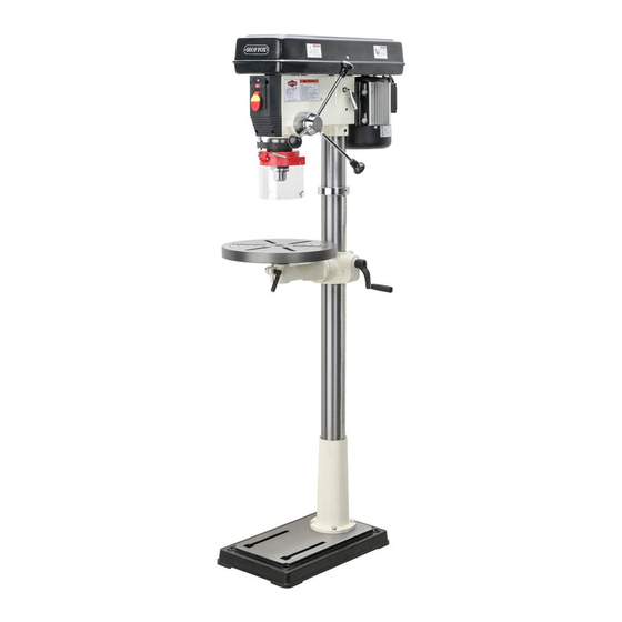
MODEL W1680
17" DRILL PRESS
INSTRUCTION MANUAL
Phone: 1-800-840-8420 • On-Line Technical Support: tech-support@woodstockint.com
COPYRIGHT © 2000 BY WOODSTOCK INTERNATIONAL, INC.
WARNING: NO PORTION OF THIS MANUAL MAY BE REPRODUCED IN ANY SHAPE OR FORM WITHOUT
THE WRITTEN APPROVAL OF WOODSTOCK INTERNATIONAL, INC.
Printed in China
Advertisement
Table of Contents

Related Manuals for Shop fox SHOP FOX W1680


Summary of Contents for Shop fox SHOP FOX W1680
-
Page 1: Instruction Manual
17" DRILL PRESS INSTRUCTION MANUAL Phone: 1-800-840-8420 • On-Line Technical Support: tech-support@woodstockint.com COPYRIGHT © 2000 BY WOODSTOCK INTERNATIONAL, INC. WARNING: NO PORTION OF THIS MANUAL MAY BE REPRODUCED IN ANY SHAPE OR FORM WITHOUT THE WRITTEN APPROVAL OF WOODSTOCK INTERNATIONAL, INC. -
Page 2: Table Of Contents
Table Of Contents PAGE INTRODUCTION ................2 ABOUT YOUR NEW DRILL PRESS ............2 WOODSTOCK SERVICE AND SUPPORT ..........2 WARRANTY AND RETURNS ..............3 MACHINE SPECIFICATIONS ..............3 SAFETY FIRST! ................4 STANDARD SAFETY INSTRUCTIONS ..........4-5 DRILL PRESS SAFETY ..............5 ELECTRICAL REQUIREMENTS ............6 AVOIDING POTENTIAL INJURIES ............7 ASSEMBLY INSTRUCTIONS ..............8... -
Page 3: Introduction
The W1680 is packaged with a drill chuck, motor, work light and pad- dle switch with removable safety key. Woodstock International, Inc. is committed to customer satisfaction in providing this manual. It is our intent to make sure all the information necessary for safety, ease of assembly, practical use and dura- bility of this product be included. -
Page 4: Warranty And Returns
® machinery complies with the provisions of any law or acts. In no event shall Woodstock International, Inc.'s liability under this war- ranty exceed the purchase price paid for the product, and any legal actions brought against Woodstock International, Inc. shall be tried in the State of Washington, County of Whatcom. We shall in no event be liable for death, injuries to persons or property or for incidental, contingent, special or consequen- tial damages arising from the use of our products. -
Page 5: Safety First
SAFETY FIRST! READ MANUAL BEFORE OPERATING MACHINE FAILURE TO FOLLOW INSTRUCTIONS BELOW WILL RESULT IN PERSONAL INJURY Indicates an imminently hazardous situation which, if not avoided, WILL result in death or serious injury. Indicates a potentially hazardous situation which, if not avoided, COULD result in death or serious injury. -
Page 6: Drill Press Safety
11. Disconnect machine when cleaning, adjusting or servicing. 12. Do not force tool. The machine will do a safer and better job at the rate for which it was designed. 13. Use correct tool. Do not force machine or attachment to do a job for which it was not designed. 14. -
Page 7: Electrical Requirements
ELECTRICAL REQUIREMENTS 110V Operation The Shop Fox ® W1680 Drill Press is supplied for This equipment must be grounded. Verify 110 volt operation, only. The motor supplied that any existing electrical outlet and circuit with your new drill press is rated at 1 horse you intend to plug into is actually grounded. -
Page 8: Avoiding Potential Injuries
AVOIDING POTENTIAL INJURIES Figure 2. Never drill, holding workpiece by hand. Figure 3. Keep fingers away from spinning tool. Fig. 4. Remove Switch Safety Key when not in use. Figure 5. Unplug machine when changing bulbs. -
Page 9: Assembly Instructions
Figure 6. This will help in identification before beginning assembly. Should any part be missing, examine the packaging carefully and check under the belt guard. If any key parts are missing, call Woodstock International, Inc. at 360- 734-3482 or tech-support@woodstockint.com. -
Page 10: Base And Column
While the main components of the Shop Fox ® W1680 Drill Press are assembled at the factory, some assembly is required. The following is the recommended sequence best suited for final assembly. ® TOOLS REQUIRED: You will need a ⁄ "... -
Page 11: Table Support
Table Support 1. Thread the 12mm table lock handle 3 turns into the table support bracket. 2. Insert the pinion into the hole on the side of the table support bracket from the inside, starting with the pinion shaft. Figure 9. Align setscrew in crank handle with flat, Figure 10, on pinion shaft and secure using the 3mm Allen... -
Page 12: Table Support
Table Support, Cont. 4. Slide the table support bracket onto the col- umn while holding the rack in place. Allow the bracket to go down until the bottom of the rack contacts the shoulder on the col- umn support. Figure 12. Secure the table with the lock handle. -
Page 13: Headstock
Head Stock The headstock repre- sents a heavy load. Seek assistance before begin- ning this step. 1. The bottom of the headstock has a pocket for inserting the column. An assistant will be needed to position the pocket over the column, as in Figure 14. -
Page 14: Handles
3. Tighten the two setscrews in Figure 16 to secure the headstock to the column Figure 16. Tighten setscrews to secure headstock. Handles Three handles are supplied with your new Drill Press. Thread them into the hub. Figure 17. Unplug the drill press before replacing the light bulb. -
Page 15: Drill Chuck And Arbor
Drill Chuck and Arbor Chuck Arbor The drill chuck is attached to the drill spindle by means of a drill chuck arbor. Matched tapers on the arbor and the back of the chuck create an almost permanent assembly when properly joined. -
Page 16: Arbor Removal
4. Slide the arbor into the spindle socket while slowly rotating drill chuck. The socket has a rectangular pocket in which the tang (or flat portion of the arbor) fits into. Once the tang is oriented correctly the drill chuck will not rotate without turning the spindle. -
Page 17: Adjustments
ADJUSTMENTS Speed Change Unplug the drill press before changing speeds to avoid accidental start up. Failure to do this may result in serious personal injury. Unplug the drill press before changing speeds. The Drill Press has 12 speeds ranging from 140 Figure 23. -
Page 18: Spindle Adjustments
More About Speed Changes The speed chart above is included to help illustrate belt changes necessary to produce a desired speed. Select the proper speed for the job at hand and find it on the speed chart above. Move the belts to the indicated location on the chart. -
Page 19: Table Adjustments
Table Adjustments The table can be adjusted for height, rotation and angle. Follow these instructions to adjust height: 1. Loosen the support bracket lock knob. Turn the table hand crank to lift or lower the table. Figure 28. 2. Always lock the support bracket in place before operating machine. -
Page 20: Operations
OPERATIONS Test Run Once assembly is complete and adjustments are done to your satisfaction, you are ready to test run the machine. Always wear safety glass- es when operating drill press. Failure to comply may result in serious per- sonal injury. Make sure the starting switch is off. -
Page 21: Drill Changes
DO NOT investigate prob- lems or adjust the drill press while it is running. Wait until the machine is turned off, unplugged and all working parts have come to a complete stop before proceeding! Drill Bit Changes Care must be taken to secure the bit firmly in Figure 32. -
Page 22: Maintenance
MAINTENANCE General Table And Base Tables can be kept rust-free with regular appli- cations of products like Boeshield ® T-9. For long term storage you may want to consider products like Kleen Bore's Rust Guardit™. Disconnect power to the machine when perform- ing any maintenance or Lubrication repairs. -
Page 23: Closure
Model W1680 as supplied when the manual was prepared. However, due to Woodstock International, Inc.’s policy of con- As with all power tools, there is danger asso- tinuous improvement, changes may be made at ciated with the Model W1680 Drill Press. -
Page 24: Wire Diagram
Your Notes: -23-... - Page 26 PART # DESCRIPTION PART # DESCRIPTION X1680027 KNOB X1680001 BASE X1680028 XPB27M HEX BOLT M12-1.75 X 30 X1680029 LOCK KNOB X1680003 RACK X1680030 SET SCREW X1680004 COLUMN X1680031 ROLL PIN X1680005 TABLE BRACKET X1680032 SNAP RING X1680006 HANDLE X1680033 SHIFTER BAR X1680007 SET SCREW X1680034...
- Page 27 PART # DESCRIPTION PART # DESCRIPTION X1680053 SLIDE BAR X1680080 SPACER X1680054 SLIDE BAR XP6207 BALL BEARING 6207ZZ X1680055 MOTOR BASE X1680082 INTERNAL RETAINING RING X1680056 WASHER X1680083 ROUND NUT 56A X1680056A SPRING WASHER X1680084 TAB WASHER X1680057 XP6206 BALL BEARING 6206ZZ X1680058 MOTOR X1680086...
- Page 28 ___Paint & Finnish Supplies ___Lumber ___$50,000-$59,999 ___$90,000 + ___Contractor’s Supplies ___Power Tools _____other________________________________________________ What is your age group? What new accessories would you like Woodstock International to carry? _________________________________________________________ ___20-29 ___50-59 _________________________________________________________ ___30-39 ___60-69 Do you think your purchase represents good value?
- Page 29 FOLD ALONG DOTTED LINE Place Stamp Here WOODSTOCK INTERNATIONAL, INC. P.O. BOX 2309 BELLINGHAM, WA 98227-2309 FOLD ALONG DOTTED LINE TAPE ALONG EDGES--PLEASE DO NOT STAPLE...
Need help?
Do you have a question about the SHOP FOX W1680 and is the answer not in the manual?
Questions and answers