
Related Manuals for Grace M201


Summary of Contents for Grace M201
- Page 1 A/D converter module owner’s manual manual Rev C all contents ©2007 Grace Design/ Lunatec LLC...
-
Page 2: Table Of Contents
Welcome Thank you for purchasing the Grace Design m201 microphone preamplifier. With the combination of unmatched sonic performance, powerful features, and solid reliability, the m201 is a powerful recording tool designed to help you make the best recordings of your career. -
Page 3: Important Safety Information
SERVICE INFORMATION The Grace Design m201 contains no user serviceable components. Contact Grace Design for repair and upgrade information. In the event that your Grace Design m201 needs to be returned to the factory, contact us for a return authorization number. -
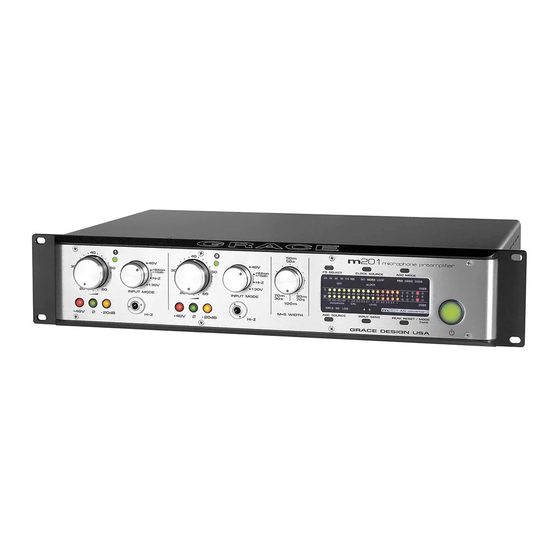
Page 4: Front Panel Controls
- 20dB HI-Z +48V - 20dB HI-Z GRACE DESIGN USA of the music signal at the input of the preamplifier. 24 position gold contact gain The switch illuminates green and provides power for switch a sealed gold contact relay located on the preamplifier Each gain control has 24 positions and adjusts the volt- circuit board. -
Page 5: Rear Panel Connections
TOSLINK LINE IN AES3 OUT LEAD FREE M+S OUT RoHS COMPLIENT GRACE DESIGN USA RIGHT LEFT MIC IN MIC IN XLR mic input connectors Input connections are made via female XLR connectors with pin 2 positive, pin 3 negative and pin 1 ground. -
Page 6: Audio Connections
50-60Hz. If your line Voltage is 230VAC then use the 240V setting. From the rear of the m201, open the trap door next to the IEC power inlet with a small screwdriver. Care- fully pull the voltage select cam straight out and then insert with the desired voltage grace design m201 owner’s manual... -
Page 7: Preamplifier Operation
-2dB to +44dB (20dB less than the 48V input), so therefor the -20dB pad is not available. This connector is balanced with the Tip positive, Ring negative and Sleeve ground. grace design m201 owner’s manual... -
Page 8: Ribbon Mic Mode
If the 48V phantom power switch is turned of and then the ribbon mode is selected, the preamplifier will wait until the phantom power voltage grace design m201 owner’s manual... -
Page 9: M-S Recording With The M201
FS SELECT CLOCK SOURCE ADC MODE 44 48 88 96 176 WORD LOOP 2WIRE CONS sLOCK OVER -60 -50 -40 -32 -28 -24 -20 -18 -16 -14 -12 -10 -8 14 16 18 20 -0.4 -0.3 -0.2 -0.1 0 0.1 0.2 0.3 0.4 <... -
Page 10: Operating The A/D Converter Module
96, 176.4, and192kHz. Whether operating on the internal crystal or an external clock source, you must select the appropriate sampling rate you wish to record at. The top left switch above the A/D bezel labeled FS SELECT is used to toggle between grace design m201 owner’s manual... -
Page 11: A/D Converter Sensitivity
Four standard sensitivities are supported in the m201 A/D converter: +18dBu = 0dBFS (14dB Headroom) +20dBu = 0dBFS (16dB Headroom) +22dBu = 0dBFS (18dB Headroom) +24dBu = 0dBFS (20dB Headroom). grace design m201 owner’s manual... - Page 12 “0” is illuminated on the m201 meter. If the current signal level is low, you need to increase the A/D sensitivity by turning the appropriate trim pot clockwise to increase the level until only the “0” is illuminated on the LED level meter. grace design m201 owner’s manual...
-
Page 13: Front Panel
CH1 (B): VR1 CH2 (B): VR4 B VR4 VR1 B 3362 3362 A VR3 VR2 A CH1 (A): VR2 CH2 (A): VR3 3362 3362 Q2 R13 Q1 C10 +18V -18V -15VA +6.5V +3.3V +15VA FRONT PANEL <figure 3 - A/D sensitivity trim pot locations>... -
Page 14: Maintenance
However, there are two adjustments that may need to be made from time to time. These procedures should be made only by a qualified service technician or at the Grace Design factory. PEAK LED ADJUSTMENT PROCEDURE The peak LED threshold levels may be adjusted to a user defined operating level. -
Page 15: Cleaning
(available at the hardware store). Apply cleaner to a clean, dry, lint free cloth and gently wipe all stainless surfaces, taking care not to allow the cleaning prod- uct to build up around the panel switches or knobs. grace design m201 owner’s manual... - Page 16 ���� ���� ���� ���� ���� ���� ���� ��� ��� ��� ��� �������� � �������� � ���� ���� ���� ���� �� �� ������ ����� <figure 4 - offset test point and peak LED adjust trim pots> grace design m201 owner’s manual...
-
Page 17: Specifications
-3dB, 12dB/octave 10Hz A/D sensitivity Range A +22dBu = 0dBFS (18dB headroom*) Range B +18dBu = 0dBFS (14dB headroom*) *can be calibrated for any setting between +18dBu = 0dBFS and +24dBu = 0dBFS grace design m201 owner’s manual... -
Page 18: Signal Flow Diagram
Signal Flow Diagram grace design m201 owner’s manual... -
Page 19: Warranty Information
Warranty Information Grace Design warrants all of our products to be free of defective parts and work- manship for a period of five years. This warranty period begins at the original date of purchase and is transferable to any person who may subsequently purchase the product during this time. -
Page 20: Manual Revisions
Initial release 04/25/2007 Changed voltage range and power specifications 04/26/2007 Power switch description changed to standby switch. 04/26/2007 Added power mains disconnect information 04/26/2007 Added signal flow diagram 04/26/2007 9-12 Added A/D module infirmation 11/08/07 grace design m201 owner’s manual...
Need help?
Do you have a question about the M201 and is the answer not in the manual?
Questions and answers