
Related Manuals for Grace m801


Summary of Contents for Grace m801
- Page 1 Manual RevB all contents ©2006 Grace Design/ Lunatec LLC...
-
Page 2: Table Of Contents
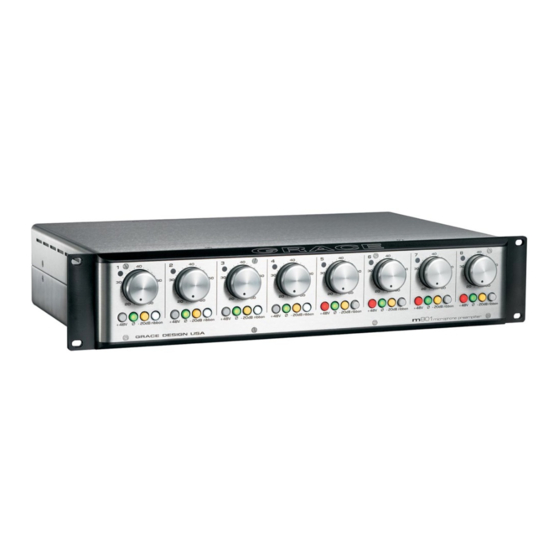
Thank you for purchasing the Grace Design m801 microphone preamplifier. With the combination of unmatched sonic performance and total reliability, the m801 is the ul- timate, state of the art microphone preamplifier solution. We have designed the m801 to be as easy and intuitive to use as possible. However, we strongly recommend that you read this product manual thoroughly to familiarize yourself with the unique features and capabilities of the m801. -
Page 3: Important Safety Information
The Grace Design m801 contains no user serviceable components. Contact Grace De- sign for repair and upgrade information. In the event that your Grace Design m801 needs to be returned to the factory, contact us for a return authorization number. -
Page 4: Front Panel Controls
+48V 20dB ribbon +48V GRACE DESIGN USA 24 pOSITION GOLd CONTACT GAIN SwITCh phASE REVERSAL SwITCh Each gain control has 24 positions and adjusts the The phase reverse switch reverses the absolute voltage gain from 18dB to 64dB in 2dB steps. for polarity of the music signal at the input of the reference, the 9 o’clock position is 28dB, the 12... -
Page 5: Rearpanel Connections
GRACE DESIGN USA m801 MIC IN MIC IN MIC IN MIC IN microphone preamplifier OUT A OUT A OUT A OUT A OUT B OUT B OUT B OUT B INPUT XLR MIC INpuT CONNECTOR XLR OuTpuT CONNECTOR... -
Page 6: Installation
72VDC can be present. Do not operate the m801 with a damaged DC power cord. Replace a damaeged DC power cord with a replacement from Grace Design. A standard AC power cable is included. for safety, the power supply cord must be connected to a grounded outlet. -
Page 7: Preamplifier Operation
Use a #10-32 x 1/2” or a #10-32 x 3/8” machine screw, no longer than 1/2” . preamplIfIer operatIon SETTING ThE GAIN First, turn the gain control fully counter-clockwise and check that the +48V phantom grace design m801 owner’s manual... -
Page 8: Maintenance
However, there are two adjustments that may need to be made from time to time. These procedures should be made only by a qualified service technician or the Grace Design factory. pEAK LEd AdJuSTMENT pROCEduRE The peak LED threshold levels may be adjusted to a user defined operating level. - Page 9 However, even the smallest differential offset at the input can result in an audible “click” when the gain control is turned. It should be noted that this type of click will be audible when no signal is present. With no signal present there is grace design m801 owner’s manual...
- Page 10 (about 20 minutes) and then re-check your adjustments. VR2 (OFFSET ADJUST) TP1 AND TP2 (OFFSET TEST POINTS) VR1(PEAK LED ADJUST) -18 +18 +15 -15 OFFSET AT132 REV R30 R34 RED WIRE figure 3 - offset test point and peak LED adjust trimpots grace design m801 owner’s manual...
-
Page 11: Specifications
IMpEdANCE Input 4350Ω output 190Ω dIMENSIONS 6.8kg) Weight 15lbs ( Height 19” Width 10” Depth POWER SUPPLY SPECIFICATIONS pOwER CONSuMpTION 100-240VAC 50/60Hz 60 Watts max dIMENSIONS Weight 6.25lbs (2.8kg) Height 1.7” Width 8.5” Depth 8.5” grace design m801 owner’s manual... -
Page 12: Cleaning And Maintenance
During the time of this warranty, Grace Design will repair or replace, at its option, any defective parts or repair defective workmanship without charge, provided the customer has appropriate proof of purchase and that the product has its original factory serial number. -
Page 13: Manual Revisions
Revision Page Change Date Initials initial release 5/23/07 all / 13 updated layout / added revision table 1/29/09 grace design m801 owner’s manual...
Need help?
Do you have a question about the m801 and is the answer not in the manual?
Questions and answers