Table of Contents

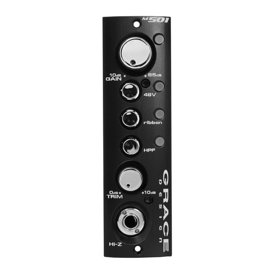
Summary of Contents for Grace m501
- Page 1 500 series microphone preamplifier module 2434 30th Street, Boulder, CO 80301 USA tel 303.443.7454 fax 303.444.4634 owner’s manual Rev A info@gracedesign.com / www.gracedesign.com all contents © Grace Design/ Lunatec LLC...
-
Page 2: Table Of Contents
303-443-7454. Our office hours are 9 to 5, Monday through Friday, MST, or you may email any technical questions to: info@gracedesign.com. Also, please check out our web site (www.gracedesign.com) for the latest Grace Design product infor- mation, owners manuals and technical documents. -
Page 3: Important Safety Information
SERVICE INFORMATION The Grace Design m501 contains no user serviceable components. Contact Grace Design for repair and upgrade information. In the event that your Grace Design m501 needs to be returned to the factory, contact us for a return authorization number. -
Page 4: Features
featUres • Fast, musical transimpedance amplifier architecture • Fully balanced, transformerless XLR microphone input • High impedance 1/4 inch instrument DI input • 12 position precision gold contact rotary switch gain control • 0.5% precision metal film resistors in signal path •... -
Page 5: M501 Connections
m501 ConneCtIons MICROPHONE INPuT The mic input is located on the back of your 500 series rack. This connector should be wired pin 2 posi- tive, pin 3 negative and pin 1 ground (check with your rack manufacturer’s documentation for connec- tor details). -
Page 6: Basic Operation
operatIng the m501 BASIC OPERATION Turn the gain and trim controls fully counter-clockwise and check that the +48V phantom power is off. Connect the microphone to the preamplifier and then turn on the phantom power switch on if required. When sending a signal to a recorder that has fixed input levels, simply increase the gain until the opti- mum recording level is reached. -
Page 7: Cable Diagrams
Cable DIagrams Use this cable when connecting the balanced XLR output to an unbalanced, 1/4” input. Balanced Output XLR Unbalanced 1/4” GROUND SHIELD (OPEN) basIC WIrIng DIagram The following is a basic overview of common wiring possibilities for the m501. All applications will vary, so please feel free to contact your dealer or us directly for setup and wiring information. -
Page 8: Specifications
speCIfICatIons GAIN RANGE (5dB steps) Mic input 10 - 65dB Hi-Z input -10 - 45dB Output trim control 0 to +10dB THD+N (1kHz, 22Hz-22kHz BW) @ 20dB Gain +20dBu out <0.00085% @ 40dB Gain +20dBu out <0.0010% @ 60dB Gain +20dBu out <0.0050% INTERMODULATION DISTORTION ( @ 40dB Gain, +20dBu out) -
Page 9: Warranty Information
Warranty InformatIon Grace Design warrants all of our products to be free of defective parts and workmanship for a period of five years. This warranty period begins at the original date of purchase and is transferable to any person who may subsequently purchase the product during this time. -
Page 10: Manual Revisions
manUal revIsIons Revision Page Change Date Initials 9/15/09 page 10...


Need help?
Do you have a question about the m501 and is the answer not in the manual?
Questions and answers