
Subscribe to Our Youtube Channel
Related Manuals for Grace m201mk2


Summary of Contents for Grace m201mk2
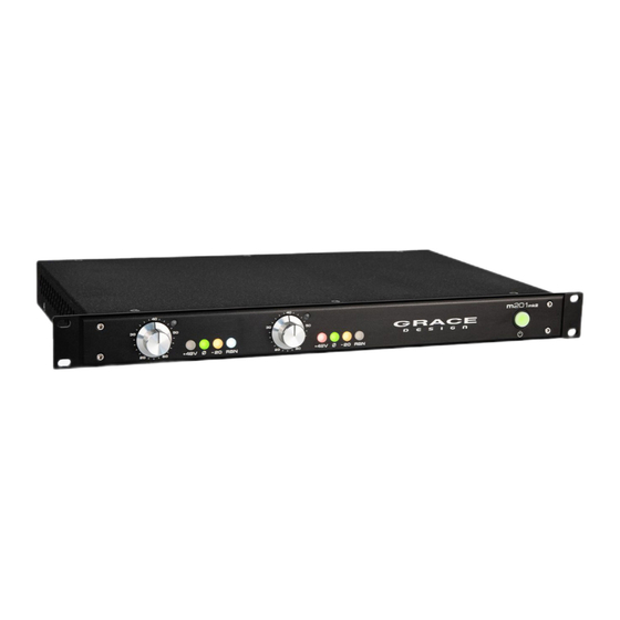
- Page 1 2 Channel Microphone Preamplfier Owner’s Manual Rev A All contents © Grace Design/ Lunatec LLC 303.823.8100 • www.gracedesign.com...
-
Page 2: Table Of Contents
We have designed the m201mk2 to be as easy and intuitive to use as possible. However, we strongly recommend that you read this manual thoroughly to familiarize yourself with the unique features and capabilities of the m201mk2. -
Page 3: Important Safety Information
The Grace Design m201mk2 contains no user serviceable components. Contact Grace Design for re- pair and upgrade information. In the event that your Grace Design m201mk2 needs to be returned to the factory, contact us for a return authorization number. -
Page 4: Front Panel Controls
1s to minimize microphone turn on transients. STANDBY SWITCH Turns power to the m201mk2 audio circuitry on PHASE REVERSAL SWITCH and off. Will illuminate green when the power is The phase reverse switch reverses the absolute polarity of the music signal at the input of the preamplifier. -
Page 5: Rearpanel Connections
Switching the rocker switch to the posi- tion turns the mains power off. The front panel standby switch turns power to the m201mk2 audio circuitry on and off and will illuminate green when the power is on. -
Page 6: Fuses
The m201mk2 uses two T250mA 250V~ 5mm x 20mm Time Delay Fuses. MOUNTING The m201mk2 can be rack mounted in a standard 19” equipment rack and does not require any extra ventilation. 4 Rack screws are included in the box. -
Page 7: Ribbon Mic Mode
10dB depending on the microphone output impedance. Maintenance The model m201mk2 was designed to be maintenance free for many years. It is highly unlikely that your unit will require service. However, there are two adjustments that may need to be made from time to time. -
Page 8: Input Offset Adjustment
INPUT OFFSET ADJUSTMENT The input amplifiers in the m201mk2 are ultra-precision laser trimmed devices which have a very low input offset. However, even the smallest differential offset at the input can result in an audible “click” when the gain control is turned. It should be noted that this type of click will be audible when no signal is present. - Page 9 PEAK LED CAL +10dB GAIN / AUTO TEST POINTS OFFSET +48V C44 J4 OFFSET TP10 +48V AT211 Rev GAIN +15V REG +10dB AUTO METER -15V REG figure 3 - offset test point and peak LED adjust trimpots grace design m201 owner’s manual...
-
Page 10: Specifications
Input Nominal 8100Ω Input Ribbon Mode 20KΩ Input Pad Engaged 1.3KΩ Output 150Ω DIMENSIONS Weight 4.6lbs (2.1kg) Height 1.7” (43mm) Width 19” (483mm) Depth 10.8” (274mm) POWER SUPPLY SPECIFICATIONS POWER CONSUMPTION 100-240VAC 50/60Hz 10 Watts max grace design m201 owner’s manual... -
Page 11: Dimensions
Dimensions grace design m201 owner’s manual... -
Page 12: Cleaning
Warranty Information The Grace Design EON limited warranty guarantees this product to be free of defective parts and workmanship for a period of twenty years. •... -
Page 13: Manual Revisions
Manual Revisions Revision Page Change Date Initials initial release 04/29/20 grace design m201 owner’s manual...
Need help?
Do you have a question about the m201mk2 and is the answer not in the manual?
Questions and answers