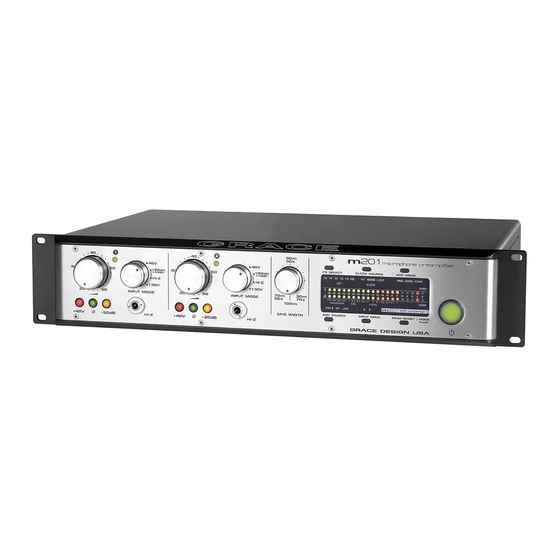
Summary of Contents for Grace M201
- Page 1 Microphone Preamplifier / ADC Owner’s Manual Rev F All contents ©2012 Grace Design...
-
Page 2: Table Of Contents
We have designed the m201 to be as easy and intuitive to use as possible. However, we strongly recommend that you read this product manual thoroughly to familiarize yourself with the unique features and capabilities of the m201. -
Page 3: Important Safety Information
The Grace Design m201 contains no user serviceable components. Contact Grace Design for re- pair and upgrade information. In the event that your Grace Design m201 needs to be returned to the factory, contact us for a return authorization number. -
Page 4: Front Panel Controls
The input mode switch is used to select between controls a sealed gold contact relay on the pream- the various types of inputs available with the m201, plifier circuit board. With the -20 switch engaged, including standard 48V, ribbon mic mode, HI-Z, or the effective gain range becomes -2dB to 44dB. -
Page 5: Rear Panel Connections
Accomodates 130V DPA© microphones via 4 pin XLR connectors. Optional A/D Converter module Optional A/D converter module for the m201 in- cludes seperate balanced analog A/D line inputs, 2x AES3 outputs (single and dual wire), word clock/ loop sync in and out, S/PDIF out and TOS- LINK optical out. -
Page 6: Audio Connections
CHECK LINE VOLTAGE SETTINGS Your m201 has been set from the factory to operate at the voltage required for your part of the world. However, it’s important to double-check this in order to ensure no damage will come to the unit if power is applied while the setting is incorrect. -
Page 7: Preamplifier Operation
60Hz. From the rear of the m201, open the trap door next to the IEC power inlet with a small screw- driver. Carefully pull the voltage select cam straight out and then insert with the desired voltage showing. Do not try to rotate the cam while it is in the power input module. Replace the fuses with the proper value selected from <figure 2>... - Page 8 M-S RECORDING In M-S mode the m201 accepts the Mid signal in channel 1 and the Side signal in channel 2. The LEFT channel output connector provides the “sum” of the inputs and the RIGHT channel output connector provides the “difference”...
-
Page 9: The Optional A/D Converter Features
The m201 A/D card is available installed on new m201’s from the factory, or as an upgrade to your existing m201. If you need more informa- tion about upgrading your m201 with the A/D module, please feel free to call us at 303.443.7454. -
Page 10: Adjusting A/D Converter Sensitivity
Simply push the button to select the input source you require. FS SELECT The m201 A/D converter can operate at sampling rates of 44.1, 48,88.2, 96, 176.4, and 192kHz. Whether operating on the internal crystal or an external clock source, you must select the appropriate sampling rate at which you wish to record. - Page 11 (in -0.1dB increments) to the left of 0. On the m201 A/D module, trim pots are used to adjust the (A) and (B) ranges for each channel. Each of these are labeled on the A/D module circuit board <figure 3>.
-
Page 12: Maintenance
<figure 3 - A/D sensitivity trim pot locations> Maintenance The model m201 was designed to be maintenance free for many years. It is highly unlikely that your unit will require service. However, there are two adjustments that may need to be made from time to time. - Page 13 INPUT OFFSET ADJUSTMENT The input amplifiers in the m201 are ultra-precision laser trimmed devices which have a very low input offset. However, even the smallest differential offset at the input can result in an audible “click”...
- Page 14 <figure 4 - offset test point and peak LED adjust trim pots> grace design m201 owner’s manual...
- Page 15 CLEANING Your m201 preamplifier chassis is constructed out of high quality stainless steel. Under normal cir- cumstances, virtually no maintenance is required to keep the unit looking shiny and new. However, if your unit becomes smudged or dirty, here are some cleaning tips: We recommend using either Pledge furniture polish or Zep brand stainless steel cleaner (available at the hardware store).
-
Page 16: Specifications
Input, ribbon mode 20kΩ Output 190Ω Peak Led Meter Green threshold -14dBu Red threshold +16dBu Weight and Dimensions dimensions 2U, 19” rack mount x 10” deep weight 16.5lbs (7.5kg) Power Consumption 100/120/230/240V~ 50-60Hz 20 Watts Max grace design m201 owner’s manual... - Page 17 -3dB, 12dB/octave 10Hz A/D sensitivity Range A +22dBu = 0dBFS (18dB headroom*) Range B +18dBu = 0dBFS (14dB headroom*) *can be calibrated for any setting between +18dBu = 0dBFS and +24dBu = 0dBFS grace design m201 owner’s manual...
-
Page 18: Signal Flow Diagram
Signal Flow Diagram grace design m201 owner’s manual... -
Page 19: Warranty Information
Warranty Information Grace Design warrants all of our products to be free of defective parts and workmanship for a period of five years. This warranty period begins at the original date of purchase and is transferable to any person who may subsequently purchase the product during this time. -
Page 20: Manual Revisions
Added power mains disconnect information 04/26/2007 Added signal flow diagram 04/26/2007 9-12 Added A/D module infirmation 11/08/07 changed fuse values for 220V-250V from 250 to 315mA 4/24/08 Fixed rearpanel A/D panel illustration 4/15/09 Changes Fuse Table values, formatting 4/9/2012 grace design m201 owner’s manual...


Need help?
Do you have a question about the M201 and is the answer not in the manual?
Questions and answers