
Related Manuals for Grace 801


Summary of Contents for Grace 801
-
Page 1: Owners Manual
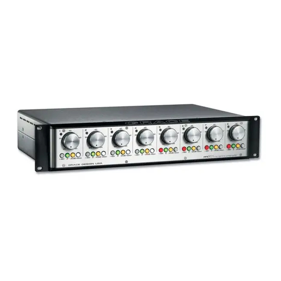
OWNERS MANUAL MODEL 801 MICROPHONE PREAMPLIFIER PO Box 204 Boulder, CO 80306 303.443.7454 fax: 303.444.4634 http://www.gracedesign.com Revision C December, 1999 © Copyright 1996, Lunatec LLC... -
Page 2: Table Of Contents
TABLE OF CONTENTS 1. OPERATION ..................2 A. FRONT PANEL CONTROLS..............2 1. GAIN CONTROL ....................... 2 2. PHANTOM POWER ....................2 3. PHASE REVERSE ....................3 4. 20dB ATTENUATOR ....................3 5. PEAK INDICATOR ....................3 6. MEMO STRIP......................3 B. -
Page 3: Operation
Thank you for purchasing the Grace design model 801 microphone preamplifier. It is built to be completely reliable and easy to use. However, there are some important instructions included in this manual. Please take the time to familiarize yourself with the installation and operation of the unit and most problems will be avoided. -
Page 4: Phase Reverse
filter capacitors discharge. As well, even if the phantom power is switched off, the LED will illuminate if voltage is being fed from an external source. (i.e. when using a direct split in a remote recording application.) 3. PHASE REVERSE The phase reverse switch (labeled ) reverses the absolute polarity of the music signal at the input of the preamplifier. -
Page 5: Installation
-20dB attenuator. Adjust the recorder input control for the optimum recording level. 2. INSTALLATION A. AUDIO TERMINATIONS 1. Input connections are made via female XLR connectors with pin 2 positive, pin 3 negative and pin 1 ground. 48V phantom power is supplied on pins 2 and 3. -
Page 6: Power Terminations
RECORDER END PREAMP END Figure 3. 600 Balanced cable termination B. POWER TERMINATIONS 1. An 8' (2.8m) DC power cord is supplied to connect the power supply unit to the preamplifier unit. This cord can be identified by the 7 pin XLR connectors at each end. -
Page 7: Grounding Options
C. GROUNDING OPTIONS 1. In certain installations, it may be desirable to separate the preamplifier signal ground from the chassis and earth grounds. Noise inducing ground loops can be broken while retaining the safety feature of the grounded AC power cord. The 801 should not be operated with a ground lift or "cheater"... -
Page 8: Mounting
However, there are two adjustments that may need to be made from time to time. These procedures should be made only by a qualified service technician or the Grace Design factory. 1. PEAK LED ADJUSTMENT PROCEDURE The peak LED threshold levels may be adjusted to a user defined operating level. - Page 9 iv. Apply power to the generator, preamplifier, then the level meter. v. Adjust the generator output level so that the preamplifier output level is at the desired red threshold. If the proper level can't be reached, adjust the preamplifier gain control. vi.
- Page 10 Figure 7. Peak LED Adj. VR1 and Offset Adj. VR2 for serial #81037 and above Figure 8. Peak LED Adj. VR1 and Offset Adj. VR2 for serial #81036 and below Page 9...
-
Page 11: Input Offset Adjustment
F. INPUT OFFSET ADJUSTMENT: The input amplifiers in the 801 are ultra precision laser trimmed devices which have a very low input offset. However, even the smallest differential offset at the input can result in an audible "click" when the gain control is turned. It should be noted that this type of click will be audible when no signal is present. - Page 12 viii. While watching the scope, turn the gain control to the 12 o'clock position and watch for the offset to change. If the trace moves in the positive direction rotate VR2 in the clockwise direction. If the trace moves in the negative direction rotate VR2 in the counter-clockwise direction.
-
Page 13: Specifications
3. SPECIFICATIONS PREAMPLIFIER SPECIFICATIONS FREQUENCY RESPONSE @ 40dB gain ± 0.2dB 20Hz-300KHz @ 40dB gain ± 3dB 4.5Hz-1.0MHz THD+N @ 40dB gain +20dBu out <.0015% INTERMODULATION DISTORTION @40dB gain +25dBu out <.0025% NOISE - REFERRED TO INPUT @60dB gain 50 source -130dB PHASE DEVIATION... -
Page 14: Schematic Diagrams
4. SCHEMATIC DIAGRAMS A. Gain Switch Assy B. Switch PCB Assy C. Power Supply PCB D. DC Input PCB E. DC Power Cable F. Audio PCB Assy Page 13...
Need help?
Do you have a question about the 801 and is the answer not in the manual?
Questions and answers