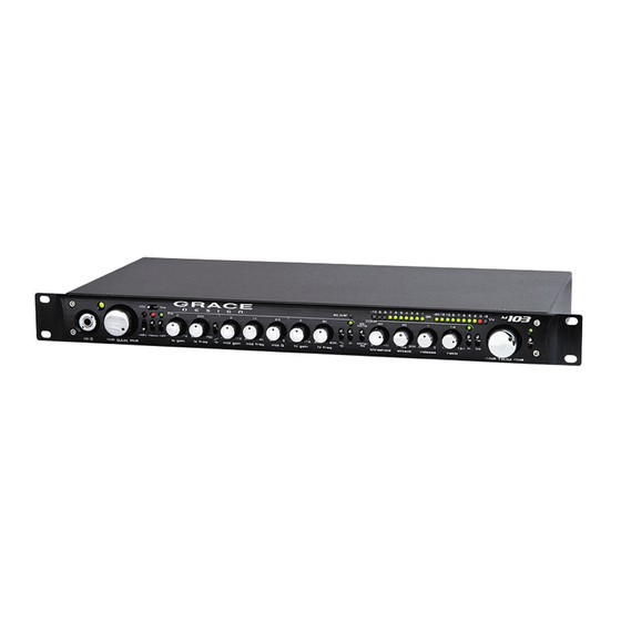
Summary of Contents for Grace m103
- Page 1 / www.gracedesign.com owner’s manual Rev A 2434 30th Street, Boulder, CO 80301 USA all contents © Grace Design/ Lunatec LLC tel 303.443.7454 fax 303.444.4634...
-
Page 2: Table Of Contents
Welcome and thanks for purchasing the Grace Design m103 channel strip. We build all of our products to be completely reliable and easy to use, so you can concentrate on making great recordings, not struggling with complicated equipment or difficult product manuals. While you will find the m103 is completely straightforward to use, we do ask that you spend a little time familiarizing yourself with this product manual to help avoid any common user difficulties. -
Page 3: Important Safety Information
SERVICE INFORMATION The Grace Design m103 contains no user serviceable components. Contact Grace Design for repair and upgrade information. In the event that your Grace Design m103 needs to be returned to the factory, contact us for a return authorization number. -
Page 4: Features
Features • Fast and musical transimpedance microphone preamplifier architecture • High fidelity audio path with 0.5% precision metal film resistors • 12 position gold plated rotary gain switch • High performance output line driver amplifiers • Ribbon mic mode (also great for dynamic mics)- Relay bypass of phantom power decoupling capacitors, increased input impedance, and 48V lockout •... - Page 5 octave filter employs a transitional Thompson - Butterworth response for the best combination of passband flatness and time domain response. LED indicator illuminates amber when active. 7. MIC / LINE switch - This switch selects which input feeds the EQ/COMP section - either the microphone preamplifier input (MIC IN from the rear panel XLR or the front panel HI-Z TRS input), or the balanced XLR LINE IN on the rear panel.
-
Page 6: Rearpanel Connections
in a more aggressive gain reduction while lower ratios will result in more gentle gain reduction. 24. COMP IN SWITCH - This switch activates the COMPRESSOR circuit. The LED above the switch illuminates when the COMP is active, turns off when deactivated. This switch controls a gold contact relay. 25. -
Page 7: Installing And Connecting The M103
Also, we strongly urge you to register your unit with Grace Design. We provide a 5 year warranty on all of our products, but if you don’t register your system it’s hard for us to help you, if and when help becomes necessary. So please take a few minutes to complete the enclosed warranty registration card and mail it in, or simply go to the warranty registration form on our web site. -
Page 8: Operating The Eq Section
input (select mic on the frontpanel mic/line switch). This circuit is totally transparent and is perfectly suited to this application. All outputs are active all the time, so you have the possibility of up to 5 live outputs if your source is MIC IN, or 3 live outputs if your source is LINE IN. -
Page 9: Operating The Comp Section
While there is no wrong way to set an equalizer, there are some general guidelines that may help you get the results you are looking for a little faster. CONTROLLING BASS FREQUENCIES In addition to the low frequency controls of the m103, we have included the 75Hz HPF on the mic preamp section. If you need to reduce rumble, wind noise or excessive proximity effect, its recommended that you start with this control, rather that putting the EQ to work at this job. - Page 10 Begin with the knob fully counterclockwise and the compressor switched ON, then slowly begin turning clockwise until you begin to compress the signal. You will hear the signal compress, and you will begin to see the GR meter light up. The lower the threshold setting , the more the incoming signal will be attenuated and the more lights will light up on the GR meter.
-
Page 11: Metering
LINK CONTROL This feature is used to link two m103 compressors together for stereo bus compression. In this application, only the compressors are linked and not the eq’s. To use this feature, simply run a standard 1/4” TRS cable between two m103s connected to the link/sidechaIn jack. -
Page 12: Block Diagram
Block Diagram... -
Page 13: Wiring Diagram
Wiring Diagram... -
Page 14: Specifications
Specifications MIC AMP SECTION MEASURED AT MIC AMP OUTPUT GAIN RANGE (5dB steps) Mic input 10-65dB Hi-Z input -10-45dB THD+N 1kHz, 22Hz-22kHz BW @ 20dB Gain +20dBu out <0.00085% @ 40dB Gain +20dBu out <0.0010% @ 60dB Gain +20dBu out <0.0050% INTERMODULATION DISTORTION @ 40dB Gain +20dBu out... - Page 15 Compressor – Inserts Pre or Post EQ Threshold Range -15 - +15 dBu Attack Range 3 – 200 ms Release Range 0.03 – 3 s Ratio Range 1:1 – 12:1 Gain Reduction 0 – 20dB THD+N 1kHz, 22Hz-22kHz BW @ 0dB Gain +20dBu out <0.002% INTERMODULATION DISTORTION @ 0dB Gain +20dBu out...
-
Page 16: Warranty Information
Warranty Information Grace Design warrants all of our products to be free of defective parts and workmanship for a period of five years. This warranty period begins at the original date of purchase and is transferable to any person who may subsequently purchase the product during this time. -
Page 17: Manual Revisions
Manual Revisions Revision Page Change Date Initials 03/01/2010...


Need help?
Do you have a question about the m103 and is the answer not in the manual?
Questions and answers