Table of Contents
Advertisement
Quick Links
Advertisement
Table of Contents

Related Manuals for Gefen EXT-HDMI1.3-242


Summary of Contents for Gefen EXT-HDMI1.3-242
- Page 1 ® 2x2 Switcher ® for HDMI EXT-HDMI1.3-242 User Manual www.gefen.com...
- Page 2 Notice Gefen, LLC reserves the right to make changes in the hard ware, packaging, and any accompanying doc u men ta tion without prior written notice. 2x2 Switcher For HDMI 1.3 is a trademark of Gefen, LLC HDMI, the logo, and High-Defi...
-
Page 3: Table Of Contents
CONTENTS Introduction Operation Notes Features Panel Layout Panel Descriptions Connecting And Operating The 2x2 Switcher For HDMI 1.3 IR Remote Control Description IR Remote Installation IR Remote Confi guration 10 IR Channel Confi guration 11 EDID Management Internal EDID External EDID 13 Specifi... -
Page 4: Introduction
The Gefen 2x2 Switcher for HDMI 1.3 Gefen’s 2x2 Switcher for HDMI 1.3 is equipped with two HDMI inputs and two HDMI outputs. Two inputs accommodate the simultaneous connection of up to two high defi... -
Page 5: Operation Notes
OPERATION NOTES READ THESE NOTES BEFORE INSTALLING OR OPERATING THE 2X2 SWITCHER FOR HDMI 1.3 • By default, display information from the display connected to HDMI output port 1 is sent back to the source. Therefore, the other display connected to the 2x2 Switcher for HDMI 1.3 must be capable of accepting the timings, resolutions and audio formats of the display that is connected to HDMI output port 1. -
Page 6: Features
Supports the use of DVI sources and DVI displays with an HDMI-to-DVI converter cable or adapter • HDMI and HDCP compliant Package Includes (1) Gefen 2x2 Switcher for HDMI 1.3 (2) 6 ft. HDMI cables (M-M) (1) IR Remote Control (1) 5V DC Power Supply (1) User Manual... -
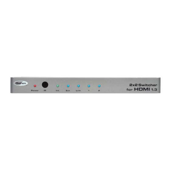
Page 7: Panel Layout
PANEL LAYOUT Front Panel Back Panel... -
Page 8: Panel Descriptions
PANEL DESCRIPTIONS Power LED Indicator This LED will become active once the included 5V DC power supply is properly connected between the unit and a open wall power receptacle. IR (Infrared) Receiver This receiver will accept command for switching between input HDMI devices using the included RMT-2IR remote control. -
Page 9: Connecting And Operating The 2X2 Switcher For Hdmi
How to Operate the 2x2 Switcher for HDMI 1.3 Use the included IR remote control unit to switch between HDMI inputs. See page 7 for a description of the IR remote control. Wiring Diagram for the Gefen 2x2 Switcher for HDMI 1.3 HDMI CABLE Hi-Def Source... -
Page 10: Ir Remote Description
IR REMOTE DESCRIPTION RMT-2IR Remote Control Unit LED Button Press Indicator This LED will be activated momentarily each time a button is pressed. Display and Source Selection Buttons These buttons are used to select which source is routed to the displays. Example: Route the source connected to Input 2 to the displays connected to Output 1 and Output 2. -
Page 11: Ir Remote Installation
IR REMOTE INSTALLATION Installing the IR Remote Control Battery Remove the battery cover on the back of the IR Remote Control unit. Insert the included battery into the open battery slot. The positive (+) side of the battery should be facing up. Replace the battery cover. -
Page 12: Ir Remote Confi Guration
IR REMOTE CONFIGURATION Setting the IR Remote Channel on the RMT-8IR In the event that IR commands from other remote controls confl ict with the supplied IR Remote Control Unit, changing the remote IR channel will fi x this issue. The IR Remote Control Unit has a bank of DIP switches for setting the Remote IR channel. -
Page 13: Ir Channel Confi Guration
IR CHANNEL CONFIGURATION Setting The IR Channel Use the following procedure to set the proper IR channel on the 2x2 Switcher for HDMI 1.3. Press and hold the EDID button. While holding the EDID button, press and release the Reset button. The input LED indicators, on the front panel, will represent the current IR channel for the Switcher: A blinking LED corresponds to DIP switch set to the ON position. -
Page 14: Edid Management
To use this mode, press the EDID button on the rear panel until the front- panel LED marked “Int” turns bright green. This mode will use a preset EDID, from the factory, that is stored in the Gefen 2x2 Switcher for HDMI 1.3. This pre-programmed standard EDID data structure is compatible with most A/V display devices. -
Page 15: External Edid
EDID MANAGEMENT External EDID Management The 2x2 Switcher for HDMI 1.3 features EDID Management. Before the source can send video or audio signals, the source device reads the EDID (Extended Display Identifi cation Data) from the output devices connected to the Splitter. The EDID contains information about what type of A/V data that the source can send to each output device. - Page 16 SPECIFICATIONS Video Amplifi er Bandwidth ............... 225 MHz Input Video Signal ................1.2V p-p Input DDC Signal ............... 5V p-p (TTL) HDMI Input Connectors ........(2) Type A, 19 Pin Female HDMI Output Connectors ........(2) Type A, 19 Pin Female Power Supply ..................
-
Page 17: Specifi Cations
Gefen warrants the equipment it manufactures to be free from defects in material and workmanship. If equipment fails because of such defects and Gefen is notifi ed within two (2) years from the date of shipment, Gefen will, at its option, repair or replace the equipment, provided that the equipment has not been subjected to mechanical, electrical, or other abuse or modifi... - Page 18 Rev B4 20600 Nordhoff St., Chatsworth CA 91311 1-800-545-6900 818-772-9100 fax: 818-772-9120 www.gefen.com support@gefen.com This product uses UL listed power supplies.
Need help?
Do you have a question about the EXT-HDMI1.3-242 and is the answer not in the manual?
Questions and answers