Advertisement
Quick Links
Advertisement

Related Manuals for Gefen EXT-HDMISB


Summary of Contents for Gefen EXT-HDMISB
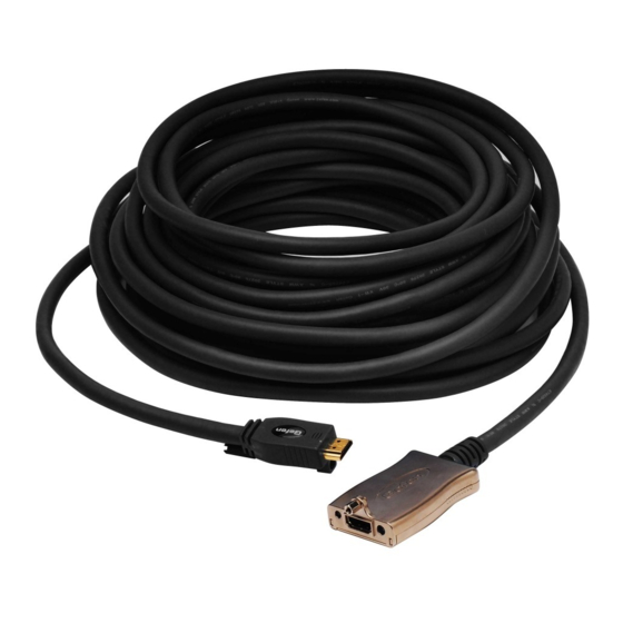
- Page 1 ® ® HDMI Super Booster Cable EXT-HDMISB User Manual www.gefen.com...
- Page 2 Chatsworth, CA 91311 www.gefen.com support@gefen.com Notice Gefen, LLC reserves the right to make changes in the hard ware, packaging and any accompanying doc u men ta tion without prior written notice. ® HDMI , the HDMI Logo, and High-Defi nition Multimedia Interface are trademarks or registered trademarks of HDMI Licensing in the United States and other countries.
-
Page 3: Table Of Contents
CONTENTS Introduction Operation Notes Features Panel Layout Connecting The HDMI Super Booster Cable Using Video Equalization To Get An Optimal Picture Specifi cations Warranty... -
Page 4: Introduction
The HDMI Super Booster Cables are a copper cable based HDMI signal extension solution with an integrated Gefen HDMI Super Booster available in the lengths of 50, 75, 100, 125 and 150 feet. The HDMI Super Booster cables will offer the highest resolution possible at any desired length with support for all resolutions up to 1080p. -
Page 5: Operation Notes
OPERATION NOTES READ THESE NOTES BEFORE INSTALLING OR OPERATING THE HDMI SUPER BOOSTER CABLE • A 5V DC power supply is included. In normal scenarios, the source powers the cable by providing a 5V signal within the cable. If the necessary voltage is not present, the included 5V DC power supply may be used to provide power. -
Page 6: Features
FEATURES Features • Perfect digital high defi nition video sent over long stretches of HDMI cables • Locate an HDMI display up to 200 feet away from any HDTV source • Supports resolutions up to 1080p, 2K, and 1920 x 1200 •... -
Page 7: Panel Layout
PANEL LAYOUT Female Side Mono-Lok™ Secure Cable Locking Nut Power LED Indicator HDMI Output Equalization Trim Pot Male Side Mono-Lok™ Secure Cable Locking Screw HDMI Male Connector... -
Page 8: Connecting The Hdmi Super Booster Cable
CONNECTING THE HDMI SUPER BOOSTER CABLE How to Connect the HDMI Super Booster Cable Connect the HDMI Super Booster Cable’s male end to the HDMI source. The male end has no lights or adjustment controls on it and is considerably smaller than the larger female end. -
Page 9: Using Video Equalization To Get An Optimal Picture
USING VIDEO EQUALIZATION TO GET AN OPTIMAL PICTURE Video Equalization using the internal DIP switches There is a small bank of switches underneath the booster chassis known as DIP switches. To use them to adjust the video behavior, use a small pointed object to push the switches ON or OFF as follows: DIP Switch 2 is not used. -
Page 10: Specifi Cations
SPECIFICATIONS Video Amplifi er Bandwidth ............... 165 MHz Input Video Signal ................1.2 Volts p-p Single Link Range ..............1080p/1920 x 1200 HDMI™ Connector .............. Type A 19 Pin Female Female Connector Dimensions ......... 1.563”W x 1.008”H x 1.05”D... - Page 14 Rev A2 20600 Nordhoff St., Chatsworth CA 91311 1-800-545-6900 818-772-9100 fax: 818-772-9120 www.gefen.com support@gefen.com...
Need help?
Do you have a question about the EXT-HDMISB and is the answer not in the manual?
Questions and answers