
Related Manuals for Canon imageCLASS 2200


Summary of Contents for Canon imageCLASS 2200
- Page 1 Series Reference Guide Reference Guide Read this guide first. Please read this guide before operating this equipment. After you finish reading this guide, store it in a safe place for future reference.
- Page 2 About the Manuals for the Machine The manuals for this machine are divided as follows. Please read them to suit your needs. Reference Guide For Basic Use ..........Troubleshooting ..........(This Document) For Basic Copying ........... Copying Guide For Convenient Copying ........For Basic Mail Box Function Use ......
- Page 3 Contains the Appendices and Index. • Considerable effort has been made to make sure that this manual is free of inaccuracies and omissions. • However, as we are constantly improving our products, if you need an exact specification, please contact Canon.
-
Page 4: Preface
PREFACE Thank you for purchasing the Canon imageRUNNER 3300/2800/2200 Series Machine. This Manual describes the use of the imageRUNNER 3300/2800/2200 Series Machine and the parts that are common to each function. Please read this manual thoroughly before operating the imageRUNNER 3300/2800/2200 Series Machine, in order to familiarize yourself with its capabilities, and to make the most of its many functions. -
Page 5: Safety Information
Safety Information A. Laser Safety This Product complies with 21 CFR Chapter 1 Subchapter J as a Class 1 laser product under the U.S. Department of Health and Human Services (DHHS) Radiation Performance Standard according to the Radiation Control for Health and Safety Act of 1968. - Page 6 CAUTION • Use of controls, adjustments or performance of procedures other than those specified in the manual may result in hazardous radiation exposure. CANON INC. 3-30-2 SHIMOMARUKO, OHTA-KU, TOKYO, JAPAN MANUFACTURED: THIS PRODUCT CONFORMS WITH DHHS RADIATION PERFORMANCE STANDARD, 21 CFR CHAPTER 1 SUBCHAPTER J.
-
Page 7: Table Of Contents
Table of Contents How This Manual Is Organized........ii PREFACE . - Page 8 Main Power and Control Panel Power ......1-23 How to Turn On the Main Power ......1-23 Control Panel Power Switch.
- Page 9 Selecting the Default Display After Auto Clear ....3-10 Setting Entry Tone, Error Tone, and Job Done Tone ....3-11 Setting Inch Input.
- Page 10 Checking and Printing Counter Information ..... .4-15 Erasing Print Totals ........4-19 Specifying Whether or Not to Accept Print Jobs of Unknown ID .
- Page 11 Chapter 7 Handling Options System Configuration ......... 7-3 Cassette Feeding Unit-W1 .
- Page 12 Card Reader-C1 ..........7-80 Operations Before Using Copy, Fax, or Mail Box Functions.
-
Page 13: How To Use This Manual
How to Use This Manual Symbols Used in This Manual The following symbols are used in this manual, for explanations of procedures and restrictions, handling cautions, and instructions that should be observed for safety. Indicates a warning concerning operations that may lead to death or injury WARNING to persons if not performed correctly. -
Page 14: Displays Used In This Manual
Displays Used in This Manual Screenshots of the touch panel display used in this manual are those taken when the Finisher-J1, Cassette Feeding Unit-W1, Feeder (DADF-H1), Printer Kit, and FAX Board are attached to the imageRUNNER 3300. Note that functions that cannot be used depending on the model or options, are not displayed on the touch panel display. -
Page 15: Safety Considerations
Safety Considerations Installation WARNING • Do not install the machine near alcohol, paint thinner, or other flammable substances. If flammable substances come into contact with electrical parts inside the machine, a fire or electrical shock may result. • Do not place the following items on the machine. If these items come into contact with a high- voltage area inside the machine, a fire or electrical shock may result. - Page 16 • Do not install the machine in such a way that the ventilation ports are blocked by objects. If the ventilation ports are blocked, heat will build up inside the machine and may result in a fire. • Do not place heavy objects on the machine, as they may tip over or fall, resulting in personal injury.
-
Page 17: Power Supply
Power Supply WARNING • Do not damage or modify the power cord. Also, do not place heavy objects on the power cord, or pull on or excessively bend it, as this could cause electrical damage and result in a fire or electrical shock. - Page 18 • Do not bundle up or tie the power cord in a knot, as this may result in a fire or electrical shock. • Insert the power cord completely into the outlet, as failure to do so may result in a fire or electrical shock.
- Page 19 • If the breaker drops to the OFF position when you turn on the power switch or when the copier is already ON, do not push the breaker back to the ON position. Doing so may lead to a fire, electrical shock, smoke, or the tripping of other breakers in the facility.
-
Page 20: Handling
Handling WARNING • Do not attempt to disassemble or modify the machine. There are high-temperature and high- voltage components inside the machine which may result in a fire or electrical shock. • If the machine makes strange noises, or emits smoke, heat or unusual smells, immediately turn off the main power switch and unplug the power plug from the outlet. - Page 21 • When moving the machine, first turn off the power switch, and then unplug the power plug. Failure to do so will damage the power cord which may cause a fire or electrical shock. • Do not drop paper clips, staples, or other metal objects inside the machine. Also, do not spill water, liquids, or flammable substances (alcohol, benzene, paint thinner, etc.) inside the machine.
- Page 22 • Do not touch the finisher while the machine is printing, as this may result in personal injury. • Do not place your hand in the part of the tray where stapling is performed while a finisher is attached, as this may result in personal injury. Saddle Finisher-G1 Finisher-J1 Safety Considerations...
-
Page 23: Maintenance And Inspections
Maintenance and Inspections WARNING • When cleaning the machine, first turn off the main power switch and unplug the power plug. Failure to observe these steps may result in a fire or electrical shock. • Clean the machine using a firmly wrung-out cloth dampened with a mild cleansing detergent. Do not use alcohol, benzene, paint thinner, or other flammable substances. - Page 24 CAUTION • Unplug the power plug from the outlet at least once a year, and clean the area around the base of the plug’s metal pins to ensure all dust is removed. If dust accumulates in this area, it may result in a fire.
-
Page 25: Consumables
Consumables WARNING • Do not throw toner cartridges into open flames, as this may cause the toner to ignite and result in burns or a fire. • Do not store toner cartridges or paper in places exposed to open flames, as this may cause the toner or paper to ignite and result in burns or a fire. -
Page 26: Warning Indications
Warning Indications WARNING • The laser unit inside the machine emits laser light. Under no circumstances open the cover of the laser unit or remove the label attached to the cover. If the laser light escapes from the machine, exposure may cause serious damage to your eyes. DANGER- Invisible laser radiation when opening the cover, removing developing assembly, or cartridges. -
Page 27: Periodic Inspection Of The Breaker
Periodic Inspection of the Breaker This machine has a breaker that detects excess current or leakage current. Be sure to test the breaker once or twice a month using the following procedure. IMPORTANT • Make sure that the main power is turned on, and the machine is neither printing nor scanning before starting a periodic inspection of the breaker. - Page 28 IMPORTANT • Do not use the test button to turn the power ON and OFF. • If the breaker lever does not go to OFF (“ ” side), repeat step 1. • If the breaker lever does not go to OFF (“ ”...
- Page 29 I side) side) Fill in the check sheet for the periodic inspection of the breaker, located at the end of this manual. Periodic Inspection of the Breaker xxviii...
-
Page 30: Legal Limitations On Scanner Usage And The Use And Printing
Legal Limitations on Scanner Usage and the Use and Printing of Scanned Images Using your scanner to reproduce certain documents, and the printing and use of such reproductions, may be prohibited by law and may result in criminal and/or civil liability. A non- exhaustive list of these document is set forth below. -
Page 31: Operation Of The Machine And Terms Used In This Manual
Operation of the Machine and Terms Used in This Manual This machine makes effective use of memory in order to perform print operations efficiently. For example, as soon as the machine has scanned the original that you want to copy, it can immediately scan the next person’s original. - Page 32 xxxi Operation of the Machine and Terms Used in This Manual...
-
Page 33: Before You Start Using This Machine
Before You Start Using This Machine CHAPTER This chapter describes what you should know before using this machine, such as main features, parts and their functions, how to turn on the main power, and so on. About the Installation Location and Handling ........1-3 Installation Precautions . - Page 34 1. Before You Start Using This Machine Orientation of Originals ............1-40 Placing an Original on the Platen Glass .
-
Page 35: About The Installation Location And Handling
About the Installation Location and Handling Installation Precautions Avoid Installing the Machine in the Following Locations Avoid locations which are subject to extremes of temperature and humidity: either low or high. For example, avoid installing the machine near water faucets, hot water heaters, humidifiers, air conditioners, heaters or stoves. - Page 36 Avoid poorly ventilated locations. During use, the machine generates ozone. However, the amount of ozone generated is not enough to affect the human body. Nevertheless, if the machine is used for a prolonged period of time in a poorly ventilated room, or when making a large quantity of prints, be sure to ventilate the room to make the working environment as comfortable as possible.
- Page 37 Avoid exposing the machine to rapid changes in temperature. If the room in which the machine is installed is rapidly heated from a low temperature, condensation may form inside the machine. This can adversely affect print quality or result in an inability to obtain print images. Avoid installing the machine near computers or other precision electronic equipment.
-
Page 38: Select A Safe Power Supply
Select a Safe Power Supply Plug the machine into a 120V AC outlet. Do not plug other electrical equipment into the outlet in which the machine is connected. Do not plug the machine into a multi-plug power strip. Doing so might cause a fire. The power cable may become damaged if it is often stepped on or if heavy objects are placed on it. -
Page 39: Handling Precautions
Moving the Machine If you intend to move the machine, contact your service representative beforehand. Handling Precautions Do not attempt to disassemble or modify the machine. Some parts inside the machine are subject to high voltages and temperatures. Take adequate precaution when inspecting the inside of the machine. Do not carry out any inspections not described in this manual. - Page 40 CAUTION • CANON RECOMMENDS THAT DATA STORED ON THE PRODUCT’S HARD DISK DRIVE BE DUPLICATED OR BACKED UP TO PREVENT ITS LOSS IN THE EVENT OF FAILURE OR OTHER MALFUNCTION OF THE HARD DISK DRIVE. NEITHER CANON NOR ANY SERVICE PROVIDER WILL BE LIABLE FOR DAMAGES FROM LOSS OF DATA STORED ON THE PRODUCT’S HARD DISK DRIVE (SEE THE TERMS OF THE PRODUCT’S LIMITED...
-
Page 41: What The Imagerunner 3300/2800/2200 Series Can Do
What the imageRUNNER 3300/2800/2200 Series Can Do Most operations of this machine are done from the touch panel display. By pressing the keys following the messages in the touch panel display, you can utilize almost all of the functions of this machine. Switching the Functions Indicated on the Touch Panel Display After the power is turned on, the following screen appears on the touch panel display. -
Page 42: Functions That Conserve Power Consumption
The Additional Functions screen The System Settings screen NOTE • Settings made in the Additional Functions screen are not changed even when you press (Reset). • For details of how to make custom settings, see ’Selecting and Storing Settings to Suit Your Needs,’ in Chapter 3. -
Page 43: Checking, Changing, And Canceling Print Jobs
NOTE • Turn the control panel power switch off when not using your machine for a prolonged period of time, for example, at night. • The Auto Sleep Time can be set from 10 seconds to 4 hours. The default setting is “2 minutes.” (See ‘Setting the Time Taken to Initiate Auto Sleep After Finishing Operations,’... -
Page 44: Displaying A Guide Screen
NOTE • For a description of functions, see ‘Checking Job and Device Status,’ in Chapter 2. • The status of each icon displayed in the screen is as follows: : Copy job : Printer job : Fax job : Box job : Error : Paper jam : Add toner... -
Page 45: Reading The Messages From The System Manager
Guide Menu This machine supports many functions. To find the right function for your particular needs or to find a simple description of a function, press (Guide) while the Basic Features screen or Special Features screen is displayed. The Guide Menu screen appears in the touch panel display as shown below. The Guide Menu screen Example: When copying photo originals: Press “Various originals.”... -
Page 46: Using Other Useful Functions
• A message board with “Done.” - If you press “Done” and close the message board, you can perform a normal operation. The message appears again when the main power is turned back on, or after Auto Clear has taken place. You can set the Auto Clear Time from 1 to 9 minutes, in one-minute increments. - Page 47 Auto Clear Function If the machine is not operated for a period of about two minutes after prints have been made or a key operation performed, it automatically returns the settings to the Standard mode. NOTE • You can set the Auto Clear Time from 0 to 9 minutes, in one-minute increments. The default setting is “2 minutes.”...
- Page 48 Auto Rotate Function Using parameters such as original size and zoom ratio, this function automatically rotates the image to the most suitable position for the set paper size. If the image does not fit on the paper even after rotation, the machine will not rotate the image but will print it as is, with part of the image cut off.
-
Page 49: Parts And Their Functions
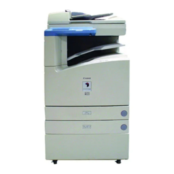
Parts and Their Functions External View When Feeder (DADF-H1), When Feeder (DADF-H1), Saddle Finisher- Finisher-J1, and Cassette G1, Inner 2way Tray-A1, Cassette Feeding Feeding Unit-W1 are attached Unit-W1, and Paper Deck-L1 are attached Parts and Their Functions 1-17... - Page 50 When Feeder (DADF-H1), Inner 2way When the platen glass cover is attached Tray-A1, and Copy Tray-F1 are attached 1 Control panel 6 Paper drawer 2 (See ‘Control Panel Parts and Functions,’ on p. 1- Holds up to 500 sheets of paper (20-lb bond (80 20.) 2 Feeder 7, 8 Paper drawer 3, 4...
-
Page 51: Internal View
Internal View 1 Front cover 8 Main power switch 2 Duplexing unit Press to the “I” side to turn the power on. (See ‘Main Power and Control Panel Power,’ on p. 1- 3 Toner box 23.) 4 Scanning area 9 Breaker 5 Rear side of platen glass cover Detects excess current or leakage current. -
Page 52: Control Panel Parts And Functions
Control Panel Parts and Functions Display Contrast Counter Check COPY MAIL BOX SCAN ON / OFF Clear Reset Stop Guide Start Additional Functions Interrupt OPER Power Error Processing/Data 1 COPY key 8 Clear key Press to use the Copy function. The Copy Basic Press to clear incorrectly entered values or Features screen appears in the touch panel characters. - Page 53 E Numeric keys H Guide key Press to enter numerical values. Press to display explanations of modes or functions in the touch panel display. F Interrupt key I Reset key Press to interrupt a continuous copying job when you need to make priority copies. Press to return the settings to the Standard mode.
-
Page 54: Checking The Counter
Checking the Counter You can check counter totals of copy, and print jobs. Counter Check Press (Counter Check) on the control panel. The counter totals are shown in the touch panel display. 1-22 Checking the Counter... -
Page 55: Main Power And Control Panel Power
Main Power and Control Panel Power The machine is provided with two power switches, a main power switch and a control panel power switch. How to Turn On the Main Power This section explains about how to turn on the main power. Make sure that the power plug is firmly inserted into the power outlet. - Page 56 The screen below is displayed until the machine is ready to scan. The screen below is displayed when the machine is ready to scan. The machine is ready to print after about 29 seconds (at a room temperature of 68°F). IMPORTANT •...
- Page 57 When a message appears on the touch panel display, follow the instructions. If the message <You must insert a control card.> appears: Insert a control card. NOTE • See ‘Card Reader-C1,’ on p. 7-80. If the message <Enter the Department ID and Password using the numeric keys.>...
-
Page 58: Control Panel Power Switch
Control Panel Power Switch Press the control panel power switch to cancel the Sleep mode and resume normal machine operations. NOTE • The machine can receive and print documents from a personal computer even when it is in the Sleep mode. Faxes can also be received during the Sleep mode. •... -
Page 59: The System Settings Of This Machine
The System Settings of This Machine It is necessary to set up the machine before using it on a network or with the printer, and fax function. Refer to the following instructions: Setting up and Connecting to the Network See the Network Guide. Installing the Printer Driver See the PS/PCL Driver Guide. -
Page 60: Using The Touch Panel Display
Using the Touch Panel Display This section describes the keys that are frequently used on the touch panel display and how they are displayed. Frequently-used Keys on the Touch Panel Display The following keys on the touch panel display are used frequently. Press to close the current setting screen, retaining the programmed settings in the Additional Functions screen. -
Page 61: Touch Panel Key Display
Touch Panel Key Display When you press a key displayed on the screen, that key is highlighted and the corresponding function (mode) is set. When you set certain functions (modes), the characters on some keys may become difficult to see, that is, the image becomes paled. You cannot press the keys with a paled image, which means that you cannot set these functions in combination with the presently set function (mode). -
Page 62: Adjusting The Brightness Of The Touch Panel Display
Adjusting the Brightness of the Touch Panel Display If the touch panel display is difficult to view, use the display contrast dial on the control panel to adjust its brightness. NOTE • To make the touch panel brighter, turn the dial counterclockwise. To make it darker, turn the dial clockwise. -
Page 63: Entering Characters From The Touch Panel Display
In screens which require alphanumeric entry, enter characters using the alphabet keys displayed in the touch panel display, as described below. Entering Alphabet Characters Example: Enter <Canon>. Press “Entry Mode” to select “Alphabet.” Each press of “Entry Mode” switches the entry mode between “Alphabet” and “Other.”... - Page 64 Enter <Canon>. <Canon> is displayed. To enter a space, press “Space.” To move the cursor, press “ ” or “ .” To enter special characters, press “Entry Mode” before you press “OK” to select “Other.” NOTE • If you make a mistake when entering characters, use “...
-
Page 65: Entering Special Characters
Entering Special Characters Example: Enter <#>. Press “Entry Mode” to select “Other.” Each press of “Entry Mode” switches the entry mode between “Alphabet” and “Other.” Press “ ” or “ ” to display the desired special character. Press “#.” “#” is displayed. Entering Characters from the Touch Panel Display 1-33... - Page 66 To enter a space, press “Space.” To move the cursor, press “ ” or “ .” To enter alphabet characters, press “Entry Mode” before you press “OK” to select “Alphabet.” NOTE • If you make a mistake when entering special letters, use “ ”...
-
Page 67: Entering In Inches
Entering in Inches When you want to enter values in inches in all modes which require numeric entry, set the inch entry function to “On” from the Common Settings of the Additional Functions screen. (See ‘Setting Inch Input,’ on 3-12.) You can then enter inches once you press “Inch” in a screen requiring numeric entry. -
Page 68: Entering The Department Id And Password
Entering the Department ID and Password When Department ID Management has been set, the Department ID and Password must be entered before operating this machine. NOTE • When you are using the control card, the message <Y ou must insert a control card.> appears in the touch panel display. - Page 69 Press (ID). Stop Start OPER Power Error g/Data The Basic Features screen of the selected function appears on the touch panel display. If the Department ID and/or Password that you entered are wrong, the message <This number has not been stored. Enter the number again.> appears. Repeat the procedure from step 1.
-
Page 70: Operations After Using Copy Functions
Operations After Using Copy Functions When your copy operations are completed, press (ID) on the control panel. Stop Start OPER Power Error g/Data The screen for entering the Department ID and Password appears. NOTE • To perform copy operations again, enter the Department ID and Password. •... -
Page 71: Placing Originals
Placing Originals Set the originals on the platen glass or in the feeder, depending on the size and type that you want to print and the settings that you have programmed. NOTE • If the original has too many pages to be placed in the feeder all at once during basic Copy/Mail Box operations, use the Job Build mode. -
Page 72: Orientation Of Originals
Orientation of Originals You can place original either vertically or horizontally. Always align the top edge of your original with the back edge of the platen glass (top left corner) or the feeder. [Platen glass] Place the original face down Place the original face down Vertical placement... -
Page 73: Placing An Original On The Platen Glass
Placing an Original on the Platen Glass You should use the platen glass when scanning books and other bound originals, heavy or lightweight paper originals, transparencies, etc., into memory. NOTE • The machine automatically detects the size of following originals: 11" x 17", LGL, LTR, LTRR, and STMTR. - Page 74 The surface that you want to scan into memory must be placed face down. Align the corner of the original with the top left corner (the arrow) of the platen glass. Place books and other bound originals on the platen glass in the same way. When enlarging LTR or STMT-size originals to 11"...
-
Page 75: Placing Originals In The Feeder (Dadf-H1)
NOTE • Remove the original from the platen glass when scanning is completed. • STMT size and postcards cannot be detected. Follow the instructions on the display and specify the original size or select the paper. Placing Originals in the Feeder (DADF-H1) Place a stack of originals in the feeder, and press (Start). - Page 76 IMPORTANT • Originals of 11-lb bond (40g/m ) or less may become creased, if used in a high temperature or high humidity environment. • Do not place the following types of originals in the feeder: - Originals with tears or large binding holes - Severely curled originals or originals with sharp folds - Clipped or stapled originals - Carbon-backed paper or other originals which might not feed smoothly...
- Page 77 IMPORTANT • Do not add or remove originals while they are being scanned. • When scanning is completed, remove the originals from the original output area to avoid paper jams. Original output area NOTE • The scanned originals are output face down to the original output area. •...
-
Page 78: Making Prints Using The Stack Bypass
Making Prints Using the Stack Bypass When making prints on transparencies, or non-standard size paper stock, load the paper stock in the stack bypass. IMPORTANT • Note the following points when using the stack bypass: - Copy quantity: 1 to about 50 sheets (stack about 1/4" (5mm) high) - Paper size: 4"... - Page 79 Free Size You can place non-standard size paper (4" x 5-1/2" to 11-3/4" x 17" (100mm x 139mm to 297mm x 432mm)). Envelope The following envelopes can be loaded into the envelope cassette: COM10, ISO-B5, Monarch, ISO-C5, DL, and Yougata 4. Open the stack bypass.
- Page 80 Adjust the slide guides to the size of the paper. Slide Guide When feeding large-size paper, pull out the auxiliary tray. Auxiliary tray Load the paper in the stack bypass. Make sure that the height of the paper stack does not exceed the limit mark ( Align the required number of sheets of paper with the slide guides.
- Page 81 Loading envelopes in the stack bypass. Take five or so envelopes, and loosen them as shown, then stack them together. Repeat this step 5 times. Place the envelopes on a clean, level surface and spread them out by hand in the direction of the arrows.
- Page 82 Hold down the four corners of the envelopes firmly, so that they and the sealed or glued portion stay flat. IMPORTANT • Do not print on the underside of the envelopes. • If the envelopes become filed with air, flatten them by hand before loading them in the envelope feeder attachment.
- Page 83 When Saddle Finisher-G1 is attached, and Image Orientation Priority is set to “On,” load the envelopes as shown below. Feeding Direction Select the paper size, and press “Next.” If envelopes are loaded, press “Envelope,” and specify the envelope type. Then press “OK”...
- Page 84 If the following screen is displayed, adjust the width of the slide guide and set the size. IMPORTANT • Set the paper size to the same size as the paper loaded in the stack bypass. • Designate which envelope type you want to set. If the envelope type is not designated correctly, a paper jam will occur.
- Page 85 Press “Done.” Paper size selected Paper size loaded presently When you press “Stack Bypass Setting,” you can set the paper size again. Place your originals, and program the copy settings. When printing documents stored in a mail box, this procedure is not necessary. NOTE •...
-
Page 86: Using The Stack Bypass While Reserving Print Jobs
Using the Stack Bypass While Reserving Print Jobs When paper is being fed from the stack bypass for the current print job, or a job is reserved, you can designate the paper to be loaded in the stack bypass for the next reserved job. Press “Stack Bypass Setting”... - Page 87 Select the paper type, and press “OK.” The paper currently loaded and the paper reserved to be loaded are displayed, as shown in the following screen. Paper size selected Paper size loaded presently Press “Done.” This completes the reserved specifications for the originals you plan to set in the feeder. Press (Start).
- Page 88 NOTE • The specified paper size is displayed when its turn comes to print. • Even when setting reserved print settings, if paper is loaded in the stack bypass, specify the same paper size and type as selected in steps 2 and 3. Otherwise, the machine does not start printing.
-
Page 89: Multi-Function Operation
Multi-function Operation The imageRUNNER 3300/2800/2200 is a multi-function machine equipped with such capabilities as Print and Fax, in addition to the Copy function. You can operate these functions together (Multi-function Operation). The following table presents details of multi- function operations. Previous job Copy Mail box... - Page 90 Previous job Printer Printing of Scanning Receiving Auto RX Printing data data Next job Documents Copy – Scanning data – Mail box Printing TX (scanning included) – Memory TX Memory RX – – Printing of Auto RX Documents Receiving data –...
-
Page 91: Available Paper Stock
Available Paper Stock Paper types which can be used with this machine are shown in the following table. The type of paper loaded in a paper drawer is indicated by the icon shown on the touch panel display for that paper drawer. (See ‘Setting a Paper Drawer for Auto Paper Selection/Auto Drawer Switching,’... - Page 92 Available Loading Place (Paper Set Place) Paper Size Length x Width Paper drawer 1, 3 Paper drawer 2, 4 Stack Bypass Paper Deck 11" x 17" 11" x 17" – – 8-1/2" x 14" – 11" x 8-1/2" LTRR 8-1/2" x 11" –...
-
Page 93: Checking Job And Device Status
Checking Job and Device Status CHAPTER Various methods of confirming and changing print jobs and additional, related functions are explained in this chapter. Flow of Checking/Changing Operations ........2-2 Checking/Canceling a Job in the Spooler . -
Page 94: Flow Of Checking/Changing Operations
Flow of Checking/Changing Operations When you press “System Monitor,” the System Monitor screen appears allowing you to check and change the status of Copy, Fax, and Print jobs. For example, you can change the order of jobs in the print queue, cancel a job, check details of a job, or print a password-protected job (secured print). - Page 95 If Job Type is selected: Press “Status.” To see jobs currently being processed or waiting to be processed, press “Status.” To see jobs that have already been processed, press “Log.” NOTE • The status of each icon displayed in the screen is as follows: : Operating : Waiting : Error...
-
Page 96: Checking/Canceling A Job In The Spooler
If “Device” is selected: The amount, type, and The status of the job size of paper loaded in currently being the paper drawers, processed is Cassette Feeding Unit- displayed. W1 (option), and Paper Deck L1 (option) are displayed. The amount of memory available (%) is displayed. - Page 97 Press “Print.” Select “Spool Status.” Press “ .” Flow of Checking/Changing Operations...
- Page 98 To cancel a job in the spooler: Select “Status.” Select the job you want to cancel spooling, and press “Cancel.” Press “Yes.” If you do not want to cancel the job, press “No.” To check the job detailed information: Select “Status” or “Log.” Select the job you want to view more details about, and press “Details.”...
-
Page 99: Checking Print Job Details
Checking Print Job Details You can check job details, such as the date and time entered, and the number of pages. Press “System Monitor,” and select the Job Type. Press “Status” or “Log.” Select the job you want to view more details about, and press “Details.”... -
Page 100: Canceling A Reserved Job
Canceling a Reserved Job You can cancel a reserved job in several ways. Canceling from the Touch Panel Display Press “Cancel” in the screen shown below, which appears while the machine is scanning, printing, or waiting to print a document. The selected job is canceled. -
Page 101: Canceling With (Stop)
Canceling with (Stop) Press (Stop). Clear Stop Start When canceling a job which is being printed, press “Cancel” on the touch panel display which appears during printing. Select the job to be canceled from the list, and press “Cancel.” You cannot select multiple documents and cancel them all at once. When canceling multiple documents, select and cancel one document at a time. -
Page 102: Canceling From The System Monitor Screen
Canceling from the System Monitor Screen You can cancel a job while it is waiting to be processed, or during printing. Press “System Monitor,” and select the Job Type. Press “Status.” Select the job to be canceled, and press “Cancel.” You cannot select multiple documents and cancel them all at once. - Page 103 Press “Yes.” If you do not want to cancel the job, press “No.” NOTE • The canceled document is displayed as <NG> on the Print Log screen. Press “Done.” The display returns to the Basic Features screen. Canceling a Reserved Job 2-11...
-
Page 104: Priority Printing
Priority Printing When you set priority printing for a job, the machine starts printing the job once the currently printing document is completed. Press “System Monitor,” and press “Print.” Press “Status.” Select the document for priority printing, and press “Print Next.” Press “Done.”... -
Page 105: Handling Print Jobs Sent From A Computer
Handling Print Jobs Sent from a Computer You can temporarily stop a print job sent from a computer, or skip an error when a print error occurs. Press “System Monitor,” and press “Print.” Select “Status.” Select the desired document, and press “Details.” Handling Print Jobs Sent from a Computer 2-13... - Page 106 Press “ .” Perform handling of the print job. When you press “Pause,” printing stops temporarily, and the key changes to “Resume.” When you press “Resume,” printing restarts, and the key changes to “Pause.” You can continue the print job even when a print error has occurred, by pressing “Auto Continue,”...
- Page 107 Press “Done.” The display returns to the Basic Features screen. Handling Print Jobs Sent from a Computer 2-15...
-
Page 108: Printing Secured Documents
Printing Secured Documents You can print documents that have been assigned a password and sent from a computer. Documents with a password are called secured documents. Secured documents waiting to be printed are displayed with a mark to the left of the job number. - Page 109 Enter the correct password, and press “OK.” Enter the same password originally assigned from the computer. The machine becomes ready to print the document. To cancel printing, press “Cancel.” The machine starts printing. If there is a current or reserved job, the machine starts printing after that job is completed. Printing Secured Documents 2-17...
-
Page 111: Selecting And Storing Settings To Suit Your Needs
Selecting and Storing Settings to Suit your Needs CHAPTER This chapter describes the initial settings and procedures to change them according to your needs. Additional Functions Settings Table ......... 3-2 Setting Specifications That Are Common to Each Function (Common Settings) . -
Page 112: Additional Functions Settings Table
Additional Functions Settings Table The following settings can be selected or stored from the Additional Functions screen. (*Indicates the factory default setting.) For more information, consult the following guides: Copy Settings ............The Copying Guide Custom Fax Settings, Communication Settings in System Settings ...The Facsimile Guide Mail Box Settings .............The Mail Box Function Guide Printer Settings ............The PS/PCL Printer Guide Network Settings in System Settings.......The Network Guide... - Page 113 Applicabl Additional Function Available settings e page Common Settings Tray A: Copy*/Printer*/Fax/Other Tray Designation Tray B: Copy/Printer/Fax*/Other* P.3-20 Tray C: Copy/Printer/Fax/Other Printing Priority 1: Copy (Priority)/2:Printer/3:Other P.3-22 Env. 1 (COM10*) Envelope Cassette Env. 2 (COM10*) P.3-23 COM10/ISO-B5/Monarch/ISO-C5/DL/Yougata 4 Standard Stack Bypass On/Off* P.3-24 Settings...
- Page 114 Applicabl Additional Function Available settings e page 10 Sec., 1, 2*, 10, 15, 20, 30, 40, 50 min., 1 hour, 90 Change Auto Sleep Time P.3-33 min., 2, 3, 4 hours 0 (no setting), 1 to 9 min. in one-minute increments, Change Auto Clear Time P.3-34 2 min.*...
- Page 115 Applicabl Additional Function Available settings e page Print List: Printer P.3-47 User’s Data List Print System Settings System Manager Settings System Manager 32 characters max. System Manager ID 7 digit number max. P.4-2 System Password 7 digit number max. E-mail Address 64 characters max.
- Page 116 Applicabl Additional Function Available settings e page Copy Settings Standard Key 1, 2 Settings All modes (No setting*) – Auto Collate On*/Off – Image Orientation Priority On/Off* – Job Duration Display On/Off* – Auto Orientation On*/Off – Photo Mode On/Off* –...
- Page 117 Applicabl Additional Function Available settings e page Custom Fax Settings Stamp Document Direct & Memory TX*, Direct TX – RX Settings – ECM RX On*/Off – Received Page Footer On/Off* – Printer Settings – Select Cassette Switch A-D Each On*, Off –...
-
Page 118: Setting Specifications That Are Common To Each Function
Setting Specifications That Are Common to Each Function (Common Settings) This section describes how to specify the settings that are common to the Copy, Mail Box, and Fax. NOTE • The Common Settings screen is made up of several screens. Use “ ”... - Page 119 Select “Copy,” “Mail Box,” or “Fax,” and press “OK.” “Fax” can only be selected when the FAX Board is attached. When main power is turned on or after Auto Clear: - If you select “Copy”: The Copy Basic Features screen appears. - If you select “Mail Box”: The Box selection screen appears.
-
Page 120: Selecting The Default Display After Auto Clear
Selecting the Default Display After Auto Clear You can select which screen to display after Auto Clear has taken place. NOTE • The duration for Auto Clear can be set. (See ‘Setting the Time Taken for the Display to Return to the Basic Features Screen After Finishing Operations,’... -
Page 121: Setting Entry Tone, Error Tone, And Job Done Tone
Setting Entry Tone, Error Tone, and Job Done Tone You can select whether or not to sound audible tones. The following tones sound at the following times: • Entry Tone: When pressing keys on the control panel or keys on the touch panel display. •... -
Page 122: Setting Inch Input
Setting Inch Input You can display the key for entering values in inches in the numeric entry screens. NOTE • The default setting is “On.” Call up the desired screen as follows: Inch Entry (Additional Functions) Select “On” or “Off,” and press “OK.” Press “Done.”... -
Page 123: Setting A Paper Drawer For Auto Paper Selection/Auto Drawer Switching
Setting a Paper Drawer for Auto Paper Selection/Auto Drawer Switching You can set the paper drawers to be used for Automatic Paper Selection and Auto Drawer Switching. This setting can be made independently for Copy, Mail Box, and other functions. This function is useful when different paper drawers are to be used for different purposes. - Page 124 Select “On” or “Off” for the stack bypass and each paper drawer, and press “OK.” To make the paper drawer eligible for APS/ADS, press “On.” To make the paper drawer ineligible for APS/ADS, press “Off.” The number of each paper drawer indicates the following locations: Stack bypass Paper drawer 1 Paper drawer 2...
-
Page 125: Identifying The Type Of Paper In A Paper Drawer
NOTE • When you select “Copy,” you can specify whether or not to set priority to paper type. - When you set “Consider Paper Type” to “On,” paper will not be fed even when paper runs out during printing, unless other loaded paper matches the size and type. For details of stored paper types, see ‘Identifying the Type of Paper in a Paper Drawer,’... - Page 126 Paper drawer 1 Paper drawer 2 Paper drawer 3 (option) Paper drawer 4 (option) Paper Deck (option) When the Cassette Feeding Unit-W1 and the Paper Deck-L1 are attached. Paper drawer 1 Paper drawer 2 Paper Deck (option) The Pedestal and the Paper Deck-L1 are attached. Select the paper type loaded in the paper drawer, and press “OK.”...
-
Page 127: Setting The Functions Keys As Keys To Reactivate The Machine
Press “Done.” Repeat this procedure. The specified mode is set and the display returns to the Basic Features screen. NOTE • The paper types stored here are displayed when selecting paper in each mode, as shown below. Setting the Functions Keys as Keys to Reactivate the Machine You can set (Copy),... -
Page 128: Setting The Energy Consumption In The Sleep Mode
Select “On” or “Off,” and press “OK.” Press “Done.” Repeat this procedure. The specified mode is set and the display returns to the Basic Features Screen. Setting the Energy Consumption in the Sleep Mode You can set the amount of energy consumed when the machine is in the Sleep mode. NOTE •... -
Page 129: Distinguishing Ltrr-Size And Stmt-Size Originals
Select “Low” or “High,” and press “OK.” Press “Done.” Repeat this procedure. The specified mode is set and the display returns to the Basic Features screen. Distinguishing LTRR-size and STMT-size Originals You can designate the way the machine handles LTRR-size or STMT-size originals placed on the platen glass. -
Page 130: Setting A Dedicated Tray For Each Function
Select “Distinguish Manually,” “Use LTRR Format,” or “Use STMT Format,” and press “OK.” When you place an LTRR or STMT-size original on the platen glass: - If you select “Distinguish Manually”: A screen allowing you to select the original size appears when scanning. - Page 131 Call up the desired screen as follows: Tray Designation (Additional Functions) Select the functions of dedicated output trays A, B, and C, and press “OK.” When the Saddle Finisher-G1 is When the Inner 2way Tray-A1 is attached attached “Fax” is displayed when the Fax board is attached. IMPORTANT •...
-
Page 132: Setting The Printing Priority
Setting the Printing Priority You can set the printing priority. A job that is set to a high priority is printed preferentially after the job currently being processed. NOTE • Priority printing will not take place even when you set the highest priority, until the current job is completed. -
Page 133: Registering The Envelope Feeder Attachment
Registering the Envelope Feeder Attachment You can use the paper drawer 1 as an envelope cassette, if you attach the Envelope Feeder Attachment and set the size switch and the paper size dial. The envelope cassette can hold the following six types of envelopes: COM10/ISO-B5/Monarch/ISO-C5/DL/Yougata 4. This section describes how to specify the type of envelopes and which cassette they are to be loaded in. -
Page 134: Setting The Standard Paper For The Stack Bypass
Setting the Standard Paper for the Stack Bypass Stores the default settings for the Stack Bypass Setting. By pressing “Stack Bypass” when making reserved prints, you can reserve by the mode that you stored here. If the Standard Stack Bypass Settings is stored when using the fax, you can receive by using the stack bypass. - Page 135 Select the paper size, and press “Next.” NOTE • To select inch size paper, press “A/B-size.” • To select free size paper, press “Free Size.” • To select envelope, press “Envelope” and select the type of envelope. Then press “OK” → “OK,”...
-
Page 136: Setting A Standard Mode For Local Printing
Press “Done.” Repeat this procedure. The specified mode is set and the display returns to the Basic Features screen. Setting a Standard Mode for Local Printing When you want to print documents in the Mail Box without changing the original settings set when they were scanned, or when you want to print documents in the Mail Box sent from a personal computer after changing the print settings, you can print using the Local Print Standard settings set in this section. - Page 137 Call up the desired screen as follows: Standard Local Print Settings (Additional Functions) Set each mode, and press “Done.” Paper Select: Select the paper source. Copies: Set the number of copies from 1 set to 2,000 sets. Finisher: Set the type of collating. Two-sided Print: Set whether or not to perform two-sided printing.
-
Page 138: Changing The Language Displayed On The Touch Panel Display
Changing the Language Displayed on the Touch Panel Display You can select the language displayed on the touch panel display. NOTE • When Language Switch is set to “On,” some characters will be restricted and not be able to be entered. -
Page 139: Returning The Common Settings To Their Defaults
Returning the Common Settings to Their Defaults With this function you can return the common settings to their defaults (initial settings). Call up the desired screen as follows: Initialize Common Settings (Additional Functions) Select “Yes.” To cancel initialization, select “No.” The screen shown below is displayed for about two seconds. -
Page 140: Setting The Timer (Timer Settings)
Setting the Timer (Timer Settings) You can set the current date and time, and specify the time taken for the machine to enter the Sleep mode. NOTE • The Timer Settings screen is made up of several screens. Use “ ”... - Page 141 Enter the current date (month, day, year) and time with (numeric keys). Enter the date, and the time in 24-hour clock as four digits without a space. Enter all four digits for the year ranging from 2000 to 2038. Examples: MAY 6 →...
- Page 142 When setting the Daylight Saving Time Settings: Press “Daylight Saving Time Settings” press “On” press “Start Date.” → → Select “Month” “Week” “Day” to specify each of them. → → Enter the time using “–” and “+,” and press “OK.” Press “End Date”...
-
Page 143: Setting The Time Taken To Initiate Auto Sleep After Finishing Operations
Press “OK.” Press “Done.” Repeat this procedure. The specified mode is set and the display returns to the Basic Features screen. Setting the Time Taken to Initiate Auto Sleep After Finishing Operations If the machine is not operated (no keys are pressed) for a certain period of time, the control panel power switch automatically switches OFF to save power. -
Page 144: Setting The Time Taken For The Display To Return To The Basic Features Screen After Finishing Operations
Enter the desired Auto Sleep Time with “ ” or “ ,” and press “OK.” The Auto Sleep Time settings are 10 seconds, 1, 2, 10, 15, 20, 30, 40, 50 minutes, 1 hour, 90 minutes, 2, 3, and 4 hours. Press “Done.”... -
Page 145: Setting The Time Taken For The Unit To Quiet Down After The Last Task
Enter the desired time period using “–” or “+,” and press “OK.” The Auto Clear Time settings are from 0 to 9 minutes (in one-minute increments). You can also enter values using (numeric keys). Press “Done.” Repeat this procedure. The specified mode is set and the display returns to the Basic Features screen. Setting the Time Taken for the Unit to Quiet Down After the Last Task This machine enters the Quiet mode after a specified amount of time has elapsed following a... -
Page 146: Setting The Time That The Unit's Power Turns Off On Different Days Of The Week
Enter the desired time period with “–” or “+,” and press “OK.” The Time Until Unit Quiets Down settings are from 0 to 9 minutes (in one-minute increments). You can also enter values using (numeric keys). Press “Done.” Repeat this procedure. The specified mode is set and the display returns to the Basic Features screen. - Page 147 Select the day of the week enter the time with (numeric → keys) press “OK.” → Enter the time in 24-hour clock as four digits without a space. Examples: 7:05 a.m.→ 0705 11:18 p.m.→ 2318 If you make a mistake when entering the time, choose the day of the week again, and enter the four-digit number.
-
Page 148: Adjusting The Machine (Adjustment/Cleaning)
Adjusting the Machine (Adjustment/Cleaning) You can perform a fine adjustment of the print image and the saddle stitch position. NOTE • The Adjustment/Cleaning screen is made up of several screens. Use “ ” or “ ” to scroll to the desired screen and make the required settings. -
Page 149: Changing The Saddle Stitch Position
Press “Done.” Repeat this procedure. The specified mode is set and the display returns to the Basic Features screen. Changing the Saddle Stitch Position When the Saddle Finisher-G1 is attached, slight position differences in the saddle stitch position may occur. With this function you can compensate for such differences. IMPORTANT •... -
Page 150: Adjusting The Standard Exposure
Use “ ” or “ ” to adjust the saddle stitch position, and press “OK.” The setting range is from –2.0mm to +2.0mm, in 0.25mm increments. Press “Done.” Repeat this procedure. The specified mode is set and the display returns to the Basic Features screen. Adjusting the Standard Exposure Adjusts the exposure adjustment scale to calibrate differences in exposure. -
Page 151: Setting Staple/Offset To On/Off
Press “Light” or “Dark” to adjust the exposure, and press “OK.” Press “Done.” Repeat this procedure. The specified mode is set and the display returns to the Basic Features screen. Setting Staple/Offset to ON/OFF If the service call message containing an error code shown below appears, be sure to turn the main power switch ON again. - Page 152 Call up the desired screen as follows: Exposure (Additional Functions) Select “On” or “Off,” and press “OK.” To disable Staple/Offset, press “Off.” To enable Staple/Offset, press “On.” Press “Done.” Repeat this procedure. The specified mode is set and the display returns to the Basic Features screen. Turn the main power switch off.
-
Page 153: Printing Reports (Report Settings)
Printing Reports (Report Settings) You can print the contents of the fax, network, and the printer settings. These reports are useful when you check the current settings. NOTE • “Report Settings” is displayed only when any of Network Interface Adapter, Printer Kit and FAX Board is attached. - Page 154 Press “Address Book List 1.” Press “Yes.” If you do not want to print, press “No.” The screen below appears, and printing starts. When printing is completed, <Print Completed> appears. To close the screen while printing, press “Done.” NOTE • To cancel printing, press “Cancel.”...
-
Page 155: Printing The User's Data List In The Network Settings
Press “Done.” Repeat this procedure. The specified mode is set and the display returns to the Basic Features screen. Printing the User’s Data List in the Network Settings You can print the user’s data list in the Network Settings when the Network Interface Adapter is attached. - Page 156 Press “User’s Data List.” Press “Yes.” If you do not want to print, press “No.” The screen below appears and printing starts. When printing is completed, <Print Completed> appears. To close the screen while printing, press “Done.” NOTE • To cancel printing, press “Cancel.” 3-46 Printing Reports (Report Settings)
-
Page 157: Printing The Contents Of The Printer Settings
Press “Done.” Repeat this procedure. The specified mode is set and the display returns to the Basic Features screen. Printing the Contents of the Printer Settings When the Printer Kit is attached, you can print the contents of the printer setting. Call up the desired screen as follows: (Additional Functions) Press “Printer”... - Page 158 Press “Yes.” If you do not want to print, press “No.” When printing is completed, the screen returns to step 3. Press “Done.” Repeat this procedure. The specified mode is set and the display returns to the Basic Features screen. 3-48 Printing Reports (Report Settings)
-
Page 159: System Manager Settings
System Manager Settings CHAPTER This chapter describes settings that can be made by the person in charge of the machine’s operation, such as the system manager. Setting Specifications of System Manager Settings (System Manager Settings)..4-2 Setting the Department ID Management . -
Page 160: Setting Specifications Of System Manager Settings (System Manager Settings)
Setting Specifications of System Manager Settings (System Manager Settings) You can set a password for the system manager. Once the System Manager ID/Password is set, restrictions can be placed on storing or changing the System Settings. IMPORTANT • Attaching the Card Reader-C1 erases the System Manager ID and Password already stored. NOTE •... - Page 161 Press “System Manager ID,” and enter a number of up to seven digits with (numeric keys) for the new System Manager ID. You must enter the System Manager ID. You cannot store a System Manager ID with only the number <0>, such as <0000000>. NOTE •...
- Page 162 Press “E-mail Address,” and enter an e-mail address for the system manager. Press “Contact Information,” and enter where to contact the system manager. Press “Comment,” and enter any comment for the system manager. Setting Specifications of System Manager Settings (System Manager Settings)
- Page 163 Once you have completed all settings, press “OK.” Press “Done.” Repeat this procedure. The display returns to the Basic Features screen. Setting Specifications of System Manager Settings (System Manager Settings)
-
Page 164: Setting The Department Id Management
Setting the Department ID Management By storing a Department ID and Password for each department, you can set the machine so that its functions can be used only after the correct password has been entered. This is called “Department ID Management.” Department IDs and Passwords for up to 300 departments can be stored. - Page 165 Press “On.” If you do not want to store a password, proceed to step 3. Press “Store Dept. ID/Password.” NOTE • For details concerning print totals, see ‘Checking and Printing Counter Information,’ on p. 4- Press “Store.” Setting the Department ID Management...
- Page 166 Press “Department ID” enter the Department ID with → (numeric keys) press “Password” enter the password in the → → same way. You cannot store a Department ID with only the number <0>, such as <0000000>. NOTE • When a password is not stored, you can use this machine by entering only the Department ID. Press “Impression Limit,”...
- Page 167 Press “OK.” Set the Impression Limit, and press “Done.” To make the “Impression Limit” set in the step 6 effective, press “Limit Impress.” “Limit Impress.” cannot be selected for a particular department. Press “OK.” NOTE • When you select “On,” Department ID Management is enabled. (See ‘Entering the Department ID and Password,’...
-
Page 168: Changing The Password And Impression Limit
Press “Done.” Repeat this procedure. When the screen below appears, enter the Department ID and Password. NOTE • For details of how to enter the Department ID and Password, see ‘Entering the Department ID and Password,’ on p. 1-36. Changing the Password and Impression Limit The following instructions describe how to change the Password and Impression Limit you have stored. - Page 169 Use “ ” and “ ” to display the Password you want to change → select the Password press “Edit.” → Enter the Password with (numeric keys), and press “OK.” To change Impression Limit, press “Impression Limit,” and enter the desired value using (numeric keys).
- Page 170 Press “Done.” Press “OK.” When you select “On,” Department ID Management is enabled. (See ‘Entering the Department ID and Password,’ on p. 1-36.) Press “Done.” Repeat this procedure. When the screen below appears, enter the Department ID and Password. NOTE •...
-
Page 171: Erasing The Department Id And Password
Erasing the Department ID and Password The following instructions describe how to erase the Department ID and Password you have stored. NOTE • When using Department ID Management with Card Reader-C1, you cannot erase the Department ID. Call up the desired screen as follows: (Additional Functions) When the System Manager ID/Password is set, enter the System Manager ID and System Password after pressing “System Settings.”... - Page 172 Press “Yes.” If you do not want to erase the Department and its settings, press “No.” The selected Department and its settings are erased. Press “Done.” Press “OK.” NOTE • When you select “On,” Department ID Management is enabled. (See ‘Entering the Department ID and Password,’...
-
Page 173: Checking And Printing Counter Information
Press “Done.” Repeat this procedure. When the screen below appears, enter the Department ID and Password. NOTE • For details of how to enter the Department ID and Password, see ‘Entering the Department ID and Password,’ on p. 1-36. Checking and Printing Counter Information You can display and print a list of the paper count for each department. - Page 174 Check or print the print totals count. The print total with the Department ID left blank (not displayed) is the total of prints from a computer not correspondent with a stored Department ID (unknown ID). If you only want to check the counter: Press “...
- Page 175 Press “Done.” Press “OK.” NOTE • When you select “On,” Department ID Management is enabled. (See ‘Entering the Department ID and Password,’ on p. 1-36.) Press “Done.” Repeat this procedure. When the screen below appears, enter the Department ID and Password. Setting the Department ID Management 4-17...
- Page 176 NOTE • For details of how to enter the Department ID and Password, see ‘Entering the Department ID and Password,’ on p. 1-36. 4-18 Setting the Department ID Management...
-
Page 177: Erasing Print Totals
Erasing Print Totals The following instructions describe how to delete the print totals made so far, for all departments. It is also possible to delete print totals for a particular department. Call up the desired screen as follows: (Additional Functions) When the System Manager ID/Password is set, enter the System Manager ID and System Password after pressing “System Settings.”... - Page 178 Select “Yes.” If you do not want to erase the counter, press “No.” Press “Done.” Press “OK.” NOTE • When you select “On,” Department ID Management is enabled. (See ‘Entering the Department ID and Password,’ on p. 1-36.) 4-20 Setting the Department ID Management...
-
Page 179: Specifying Whether Or Not To Accept Print Jobs Of Unknown Id
Press “Done.” Repeat this procedure. When the screen below appears, enter the Department ID and Password. NOTE • For details of how to enter the Department ID and Password, see ‘Entering the Department ID and Password,’ on p. 1-36. Specifying Whether or Not to Accept Print Jobs of Unknown ID You can specify whether or not to print documents from a computer not correspondent with a stored Department ID. - Page 180 Select “On.” NOTE • When you select “On,” Department ID is enabled. (See ‘Entering the Department ID and Password,’ on p. 1-36.) Select “On” or “Off,” and press “OK.” If you want to print from a computer not correspondent with a stored Department ID, press “On.”...
- Page 181 Press “Done.” Repeat this procedure. When the screen below appears, enter the Department ID and Password. NOTE • For details of how to enter the Department ID and Password, see ‘Entering the Department ID and Password,’ on p. 1-36. Setting the Department ID Management 4-23...
-
Page 182: Setting Device Information (Device Information Settings)
Setting Device Information (Device Information Settings) You can set a name for this machine and specify its location. Call up the desired screen as follows: (Additional Functions) When the System Manager ID/Password is set, enter the System Manager ID and System Password after pressing “System Settings.”... -
Page 183: Erasing The Message Board (Clear Message Board)
Erasing the Message Board (Clear Message Board) The “Message Board” is a function used by the system manager to display messages for users of this machine on the touch panel display. Message board settings are done from the Remote UI, however, erasing a message board can be done from the main unit as well. Call up the desired screen as follows: (Additional Functions) When the System Manager ID/Password is set, enter the System Manager ID and System... -
Page 184: Setting The Auto Offline On/Off (Auto Offline)
Setting the Auto Offline On/Off (Auto Offline) When the network is online, scanning is not possible with the Copy, Mail Box, or Fax functions. By setting Auto Offline to “On,” the machine will automatically go Offline. NOTE • “Auto Offline” is displayed only when the Network Scan function is enabled. •... - Page 185 Routine Maintenance CHAPTER This chapter describes how to load paper, add toner, and perform routine cleaning. Loading Paper ............5-2 Loading Paper in the Paper Drawers .
-
Page 186: Loading Paper
Loading Paper This section describes how to load paper in the paper drawers. NOTE • The following paper sizes can be loaded in the paper drawers: - Paper drawers 1, 3: LGL, LTR, LTRR, STMT, and STMTR - Paper drawers 2, 4: 11" x 17", LGL, LTR, LTRR, STMT, and STMTR - Paper drawers 3 and 4 can be used when the Cassette Feeding Unit-W1 (option) is attached. - Page 187 Press and release the button of the paper drawer in which you want to load paper. Grip the handle and pull out the paper drawer until it stops. Open a package of paper, and remove the paper stack. Loading Paper...
-
Page 188: Paper Drawer
NOTE • For high-quality print output, use paper recommended by Canon. Turn the opened surface of the paper stack over, and place it in the paper drawer. Even out the edges of the paper stack. Load the paper stack against the right wall of the paper drawer. - Page 189 Gently push the paper drawer back into the machine until it clicks. CAUTION • When returning the paper drawer to its original position, be careful not to get your fingers caught, as this may result in personal injury. IMPORTANT • Never place paper or any other items in the open part of the paper drawer next to the paper stack.
-
Page 190: Adjusting A Paper Drawer To Hold A Different Paper Size
Adjusting a Paper Drawer to Hold a Different Paper Size If you want to load a new paper size in a paper drawer, follow the procedure described below to adjust the paper drawer guides. NOTE • The following paper sizes can be loaded in the paper drawers: - Paper drawers 1, 3: LGL, LTR, LTRR, STMT, and STMTR - Paper drawers 2, 4: 11"x17", LGL, LTR, LTRR, STMT, and STMTR - Paper drawers 3 and 4 can be used when the Cassette Feeding Unit-W1 (option) is attached. - Page 191 Squeeze the lever on the front guide, as shown below. Without releasing the lever, slide the front guide to align it with the mark for the desired paper size. Front Guide IMPORTANT • Not adjusting the guides correctly may cause paper jams, dirty prints, or make the inside of the machine dirty.
- Page 192 Set the paper size dial, located on the right side of the paper drawer, to match the paper being loaded. IMPORTANT • Not setting the paper size dial correctly, results in the display of an incorrect paper size on the touch panel display.
-
Page 193: Adding Toner
• When the <Add toner.> message appears, approximately 300 prints can still be made (LTR-size Canon Standard Chart). However, since this number may vary depending upon the original, it is recommended that toner be added as soon as possible. •... - Page 194 Open the front cover of the main unit. Pull the blue lever down. Grip the blue handle on the toner box. Pull out the toner box until it stops. 5-10 Adding Toner...
- Page 195 Hold the new toner cartridge in your hands, as shown below, and rock it several times to the left and right. Place the toner cartridge on the toner box, as shown below, and push it in as far as possible. Push the toner cartridge down, to lock it in place on the toner box.
- Page 196 Pull the black cartridge knob, until the stop sign appears. Lightly tap the top of the toner cartridge to cause the toner to empty into the toner box. Push the black toner box handle back to its original position. The toner cartridge will be pushed in, along with the toner box. 5-12 Adding Toner...
- Page 197 Make sure the toner cartridge comes loose from the toner box when you push the black handle back to the position indicated by the arrows. Remove the empty toner cartridge from the toner box. WARNING • Do not throw used toner cartridges into open flames, as this may ignite the toner remaining inside the cartridge, and result in burns or a fire.
- Page 198 Push the toner box back to its original position. Pull the blue lever up to its original position. Close the front cover of the main unit. 5-14 Adding Toner...
-
Page 199: Routine Cleaning
Routine Cleaning If the original is not copied clearly, clean the following parts of the machine. For high-quality output, we recommend cleaning these parts once a month. • Platen glass • Rear side of the platen glass • Feeder scanning area •... -
Page 200: Cleaning The Platen Glass/Rear Side Of Platen Glass Cover
Cleaning the Platen Glass/Rear Side of Platen Glass Cover Clean the platen glass and the rear side of platen glass cover following the procedure below. IMPORTANT • If the platen glass or the rear side of the platen glass cover is dirty, the original may not be scanned cleanly, or the size of the original may be detected incorrectly. -
Page 201: Cleaning The Feeder 1
Cleaning the Feeder If your originals have black streaks or appear dirty after copying them using the feeder, this may be caused by pencil writing rubbing off the originals and onto the roller. Perform this feeder cleaning procedure to clean the feeder scanning area, white plate, and roller. IMPORTANT •... - Page 202 Open the middle cover, holding the knob in the front. Clean the transparent plastic part of the middle cover with a cloth dampened with water. Close the middle cover. CAUTION • When closing the cover, be careful not to get your fingers caught, as this may result in personal injury.
- Page 203 Close the feeder cover. CAUTION • When closing the cover, be careful not to get your fingers caught, as this may result in personal injury. Open the feeder. Clean the feeder scanning area (platen glass) and the metal part located next to the rubber roller, with a cloth dampened with water. Routine Cleaning 5-19...
-
Page 204: Cleaning The Feeder
Close the feeder. Cleaning the Feeder You can also clean the roller by repeatedly feeding blank paper sheets through the feeder. NOTE • “Adjustment/Cleaning” is made up of several screens. Select the desired item by pressing “ ” or “ .” •... -
Page 205: Roller Cleaning
While the feeder is being cleaned, the screen below appears. Press “Done.” Repeat this procedure. The display returns to the Basic Features screen. Roller Cleaning If dirt appears on printed paper, clean the roller in the main unit as the need arises. NOTE •... - Page 206 Press “Start.” To cancel Roller Cleaning, press “Cancel.” While the roller is being cleaned, the screen below appears. Press “Done.” Repeat this procedure. The display returns to the Basic Features screen. 5-22 Routine Cleaning...
-
Page 207: Consumables And Options
Consumables and Options The following consumables and accessories are available from Canon. For details, consult your service representative. We recommend that you order paper stock and toner from your service representative before you run out of them. Consumables Paper Stock In addition to plain paper (11"... - Page 208 Genuine Supplies Canon has developed and manufactured parts, supplies, and GPR-6 Toner specifically for use in this machine. For superior print quality, we recommend that you use Canon- GENUINE brand parts, supplies, and GPR-6 Toner in this machine. Ask your authorized Canon dealer or service provider for Canon-GENUINE brand parts, supplies, and GPR-6 Toner.
-
Page 209: Options
Stamp Cartridge This ink cartridge is used to stamp originals when they are sent. (For the Fax function.) Options Cassette-U1 You can adjust this cassette to suit the paper size you want to load. (See ‘Adjusting a Paper Drawer to Hold a Different Paper Size,’ on p. 5-6) -Available locations: paper drawer 2 and 4 -Available paper sizes: 11"x17", LGL, LTR, LTRR, STMT, and STMTR Consumables and Options... - Page 210 Cassette-V1 You can adjust this cassette to suit the paper size you want to load. (See ‘Adjusting a Paper Drawer to Hold a Different Paper Size,’ on p. 5-6) -Locations to set: paper drawer 1 and 3 -Available paper sizes: LGL, LTR, LTRR, STMT, and STMTR 5-26 Consumables and Options...
-
Page 211: Troubleshooting
Troubleshooting CHAPTER This chapter describes what to do in response to a paper jam in the main unit or an error message display. Clearing Paper Jams ........... . 6-2 Screen Shown When There Is a Paper Jam . -
Page 212: Clearing Paper Jams
Clearing Paper Jams If a paper jam occurs, the following screen appears on the touch panel display. Screen Shown When There Is a Paper Jam The screen indicating the location of the paper jam appears on the touch panel display, followed by instructions on how to clear the paper jam. - Page 213 CAUTION • When removing jammed originals or paper, take care not to cut your hands on the edges of the original or paper. • When removing jammed paper or when inspecting the inside of the machine, do not allow necklaces, bracelets, or other metal objects to touch the inside of the machine, as this may result in burns or electrical shock.
- Page 214 If a paper jam occurs within the optional units, see the instructions on the following pages. Cassette Feeding Unit-W1 (See ‘Clearing Paper Jams in the Cassette Feeding Unit-W1,’ on p. 7-5.) Paper Deck-L1 (See ‘Clearing Paper Jams in the Paper Deck-L1,’ on p. 7-10.) Feeder (DADF-1) (See ‘Clearing Paper Jams in the Feeder,’...
- Page 215 Finisher-J1 (See ‘Clearing Paper Jams in the Finisher-J1,’ on p. 7-37.) Saddle Finisher-G1 (See ‘Clearing Paper Jams in the Saddle Finisher-G1,’ on p. 7-52, ‘Clearing Paper Jams in the Saddle Stitcher Unit,’ on p. 7-54, ‘Clearing Paper Jams in the Puncher Unit,’...
-
Page 216: Clearing Paper Jams In The Main Unit
After you have cleared all paper jams at the locations indicated on the touch panel display, restore all levers and covers to their original positions. Continue operations, following the instructions displayed on the touch panel display. Once you have cleared the paper jam in locations other than the feeder, the print operation restarts. - Page 217 Move the green lever in the direction of the arrow. Remove any paper remaining in the fixing unit. Turn the green knob (2 places) in the direction of the arrow, and remove any jammed paper. CAUTION • The parts located around the knob are subject to high temperatures. When removing jammed paper, take care not to touch anything in this area except the green knob.
- Page 218 Return the green lever to its original position. Close the front cover of the main unit. CAUTION • When closing the cover, be careful not to get your fingers caught, as this may result in personal injury. Follow the instructions on the touch panel display. NOTE •...
-
Page 219: Clearing Paper Jams In The Duplexing Unit
Clearing Paper Jams in the Duplexing Unit If a paper jam occurs in the duplexing unit, a screen similar to the one shown below appears on the touch panel display. Check where the jam occurred, and follow the procedure described below and the procedure that appears on the touch panel display, to remove the jammed paper. - Page 220 Return the green lever to its original position. Close the front cover of the main unit. CAUTION • When closing the cover, be careful not to get your fingers caught, as this may result in personal injury. Follow the instructions on the touch panel display. NOTE •...
-
Page 221: Clearing Paper Jams In The Exit Slot
Clearing Paper Jams in the Exit Slot If a paper jam occurs in the exit slot, a screen similar to the one shown below appears on the touch panel display. Check where the jam occurred, and follow the procedure described below and the procedure that appears in the touch panel display, to remove the jammed paper. - Page 222 Move the green lever in the direction of the arrow. Open the lower left cover of the main unit. Lift the green lever and remove any jammed paper. CAUTION • The parts located around the green lever of the exit slot guide are subject to high temperatures.
- Page 223 Close the lower left cover. CAUTION • When closing the cover, be careful not to get your fingers caught, as this may result in personal injury. Return the green lever to its original position. Close the front cover. CAUTION • When closing the cover, be careful not to get your fingers caught, as this may result in personal injury.
-
Page 224: Clearing Paper Jams In The Upper Right Cover
Follow the instructions on the touch panel display. NOTE • For details of the screen indicating how to clear the paper jam, see ‘Screen Shown When There Is a Paper Jam,’ on p. 6-2. Clearing Paper Jams in the Upper Right Cover If a paper jam occurs inside the upper right cover, a screen similar to the one shown below appears on the touch panel display. - Page 225 Remove any jammed paper. Close the upper right cover of the main unit. When the Paper Deck-L1 (option; see p. 7-9) is attached, reattach the paper deck to the main unit. CAUTION • When closing the cover, be careful not to get your fingers caught, as this may result in personal injury.
-
Page 226: Clearing Paper Jams In The Stack Bypass
Clearing Paper Jams in the Stack Bypass If a paper jam occurs in the stack bypass, a screen similar to the one shown below appears on the touch panel display. Check where the jam occurred, and follow the procedure described below and the procedure that appears on the touch panel display, to remove the jammed paper. - Page 227 Close the stack bypass. Open the upper right cover of the main unit. When the Paper Deck-L1 (option; see p. 7-9) is attached, move the paper deck away from the main unit. Remove any jammed paper. Clearing Paper Jams 6-17...
- Page 228 Close the upper right cover of the main unit. When the Paper Deck-L1 (option; see p. 7-9) is attached, reattach the paper deck to the main unit. CAUTION • When closing the cover, be careful not to get your fingers caught, as this may result in personal injury.
-
Page 229: Clearing Paper Jams In A Paper Drawer
Clearing Paper Jams in a Paper Drawer If a paper jam occurs in a paper drawer, a screen similar to the one shown below appears on the touch panel display. Check where the jam occurred, and follow the procedure described below and the procedure that appears on the touch panel display, to remove the jammed paper. - Page 230 Remove any jammed paper. Press and release the paper drawer release button of the paper drawer indicated on the touch panel display, until the paper drawer releases. Pull out the paper drawer. 6-20 Clearing Paper Jams...
- Page 231 Remove any jammed paper. Return the paper drawer to its original position. CAUTION • When returning the paper drawer to the original position, be careful not to get your fingers caught, as this may result in personal injury. Close the upper right cover of the main unit. When the Paper Deck-L1 (option;...
- Page 232 Follow the instructions on the touch panel display. NOTE • For details of the screen indicating how to clear the paper jam, see ‘Screen Shown When There Is a Paper Jam,’ on p. 6-2. 6-22 Clearing Paper Jams...
-
Page 233: Frequently Occurring Paper Jams
Frequently Occurring Paper Jams If paper jams occur frequently, even though the machine seems to be in proper working order, follow the procedure below to clean the static charge eliminator. NOTE • If paper jams occur frequently, make sure that the size set on the paper size dial of the drawers matches the size of the paper loaded in the drawer. - Page 234 Remove the static charge eliminator cleaning brush. Clean the groove of the static charge eliminator, as shown below. Insert the brush of the static charge eliminator cleaner into the groove, and carefully move the brush back and forth in the groove. When you have finished cleaning the groove, return the static charge eliminator to its original position.
- Page 235 Return the brush to its original position. Close the front cover of the main unit. Frequently Occurring Paper Jams 6-25...
-
Page 236: List Of Error Messages
List of Error Messages Self-diagnostic Display If a self-diagnostic message appears, follow the instructions on the touch panel display. Self-diagnostic (error) messages appear on the touch panel display at the following times: • When printing cannot be performed because of an operational error. •... - Page 237 Remove the paper from the output tray. Cause Prints from the previous job remain in the output tray. Remedy Remove the prints from the output trays. Attach the finisher to the main unit. Cause The finisher is not properly connected to the main unit. Remedy Connect the finisher to the main unit properly.
-
Page 238: List Of Error Codes Without Messages
Remove the original from the platen glass. Cause The original remains on the platen glass. Remedy Remove the original from the platen glass, and place the original again. Remove the original from the feeder. Cause The original is placed both in the feeder and on the platen glass in a specified mode with which the feeder cannot be used. - Page 239 #851 Cause : Not enough memory in the main unit, or the scanned document can- not be stored because there are more than 100 documents in the specified mail box. Remedy : Check the available memory of the main unit, and delete unwanted documents in the memory boxes.
-
Page 240: If Memory Becomes Full During Scanning
If memory becomes full during the scanning of originals, the following messages appear on the touch-panel display. NOTE • The machine’s memory can hold about 3,700 originals (LTR-size Canon Standard Chart, Standard setting), scanned in the standard mode. Follow this procedure: If the message asking whether to print the original pages scanned into memory appears: To print the pages scanned into memory, select “Yes.”... -
Page 241: Service Call Message
Service Call Message If a malfunction occurs and the machine cannot operate normally, the message below (the service call message) appears on the touch panel display. WARNING • Do not insert or unplug the power plug with wet hands, as this may result in electrical shock. - Page 242 Turn the main power switch off. Allow at least three seconds before turning the main power switch back on. side) ( I side) If the machine still does not operate normally, follow the procedure below, and contact your service representative. Turn off the main power.
- Page 243 NOTE • When you contact your service representative, have the following information on hand: - Product name - Details of the malfunction - The error code displayed on the touch panel display Service Call Message 6-33...
-
Page 244: When The Power Does Not Turn On (Checking The Breaker)
When the Power Does Not Turn On (Checking the Breaker) If this machine does not operate, even though the main power switch and the control panel switch are both ON, always check that the breaker is not OFF. If the breaker is OFF, contact your service representative without switching the breaker back ( I side) side) WARNING... - Page 245 Handling Options CHAPTER This chapter describes the use of options and what to do if there is a paper jam in an optional unit. System Configuration ........... . 7-3 Cassette Feeding Unit-W1 .
- Page 246 7. Handling Options Removing Punch Waste ............7-70 Consumables .
-
Page 247: System Configuration
System Configuration The following options can be attached to the machine. Main unit 1 Feeder (DADF-H1) 5 Paper Deck-L1 2 Finisher-J1 6 Saddle Finisher-G1 3 Cassette Feeding Unit-W1 7 Puncher Unit-K1 4 Inner 2way Tray-A1 8 Card Reader-C1 (Control Card) 9 Copy Tray-F1 System Configuration... -
Page 248: Cassette Feeding Unit-W1
Cassette Feeding Unit-W1 If you attach the Cassette Feeding Unit-W1 to the machine, you have two additional sources of paper for printing jobs. Up to 500 sheets of paper can be loaded in each drawer of the cassette feeding unit. Parts and Their Functions 1 Drawers 2 Lower right cover... -
Page 249: Clearing Paper Jams In The Cassette Feeding Unit-W1
Clearing Paper Jams in the Cassette Feeding Unit-W1 If a paper jam occurs in the Cassette Feeding Unit-W1, a display similar to the one shown below appears on the touch panel display. Check where the jam occurred, and follow the procedure described below and the procedure that appears on the touch panel display, to remove the jammed paper. - Page 250 Open the lower right cover of the main unit. When the Paper Deck-L1 (option) is attached, move the paper deck away from the main unit; see p. 7-9 before opening the cover. Remove any jammed paper. Press and release the paper drawer release button of the paper drawer indicated in the touch panel display.
- Page 251 Pull out the paper drawer. Remove any jammed paper. Return the paper drawer to its original position. CAUTION • When returning the paper drawer to its original position, be careful not to catch your fingers between the top of the paper drawer and the main unit. Cassette Feeding Unit-W1...
- Page 252 Close the lower right cover. When the Paper Deck-L1 (option) is attached, reattach the paper deck to the main unit; see p. 7-9. CAUTION • When closing the cover, be careful not to get your fingers caught, as this may result in personal injury.
-
Page 253: Paper Deck-L1
Paper Deck-L1 If you attach the Paper Deck-L1 to the machine, you have one additional source of paper for printing jobs. Up to 2,500 sheets (20-lb bond (80g/m )) of paper can be loaded in the paper deck. IMPORTANT • When the machine is in the Sleep mode (the touch panel is not displayed, and only the main power indicator is lit), you may not be able to open the paper deck. -
Page 254: Clearing Paper Jams In The Paper Deck-L1
Clearing Paper Jams in the Paper Deck-L1 If a paper jam occurs in the Paper Deck-L1, a screen similar to the one shown below appears on the touch panel display. Check where the jam occurred, and follow the procedure described below and the procedure that appears on the touch panel display, to remove the jammed paper. - Page 255 Remove any jammed paper. Press the Open button to open the paper deck. Remove any jammed paper. Paper Deck-L1 7-11...
-
Page 256: Loading Paper In The Paper Deck
Close the paper deck and reconnect it to the main unit. CAUTION • When reconnecting the paper deck to the main unit, be careful not to get your fingers caught, as this may result in personal injury. Follow the instructions on the touch panel display. NOTE •... - Page 257 Rewrap any remaining paper in its original package, and store it in a dry place, away from direct sunlight. NOTE • For high-quality print output, use paper recommended by Canon. Load the paper deck with the paper with its opened surface face up. Paper Deck-L1 7-13...
- Page 258 IMPORTANT • If the paper is curled, curl it down before placing it in the paper drawer. • Make sure that the height of the paper stack does not exceed the limit mark ( ) at the back of the paper drawer. •...
-
Page 259: Envelope Feeder Attachment-B1
Envelope Feeder Attachment-B1 Parts and Their Functions When the Envelope Feeder Attachment is attached to Paper Drawer 1: 1 2 3 1 Left guide 4 Front width guide Align to the length of envelopes being loaded. 5 Size switch Select either “ENV.1” or “ENV.2” for the envelope 2 Envelope receptacle cassette. -
Page 260: How To Use The Envelope Feeder Attachment
How to Use the Envelope Feeder Attachment The following six types of envelopes can be loaded into the Envelope Feeder Attachment: COM10, Monarch, DL, ISO-B5, ISO-C5, and Yougata 4. The main unit and the Envelope Feeder Attachment are set so that COM10 envelopes can be loaded without any adjustment. When using COM10 envelopes, load them (See ‘Loading Envelopes,’... -
Page 261: Before Loading The Envelopes
• The main unit and the Envelope Feeder Attachment are set so that COM10 envelopes can be loaded without any adjustment. The guide sizes can be changed so that the following envelopes can be loaded. Using envelopes other than these can result in paper jams, dirty prints and the inside of the machine becoming dirty. - Page 262 Place the envelopes on a clean, level surface and spread them out by hand in the directions of the arrows. Repeat this step five times. IMPORTANT • Take particular care to spread the envelopes out in the direction they will be fed. Hold down the four corners of the envelopes firmly, so that they and the sealed or glued portion stay flat.
-
Page 263: Loading Envelopes
IMPORTANT • Do not print on the underside of the envelopes (the side with the flap). • If the envelopes become filled with air, flatten them by hand before loading them in the envelope feeder attachment. Loading Envelopes This section explains how to load envelopes in the drawer. Press and release the button of the paper drawer in which you want to load envelopes. - Page 264 Grip the handle and pull out the paper drawer until it stops. Squeeze the lever on the left guide, as shown below, and pull out the left guide as far as possible. Load the envelopes with the printing surface face down, as shown below.
- Page 265 Load the envelopes in the direction shown below. Front Side Align the leading edges of the envelopes, and make sure that they are held in place under the claw. IMPORTANT • If any envelopes are curled, flatten them out before placing them in the envelope cassette. •...
- Page 266 Squeeze the lever on the left guide, and set the left guide at the trailing edge of the envelopes. Gently slide the paper drawer back into the machine until it clicks into place in the closed position. CAUTION • When returning the paper drawer to its original position, be careful not to get your fingers caught, as this may result in personal injury.
-
Page 267: Type Of Envelope
Adjusting the Envelope Feeder Attachment to Hold a Different Type of Envelope This section explains how to load envelopes of types other than the one currently specified in the Additional Functions screen. Press and release the button of the paper drawer in which you want to load envelopes. - Page 268 Pull out the paper drawer by lifting it, holding the left and right sides of the paper drawer with both hands. Select either <ENV.1> or <ENV.2> for the envelope cassette. When selecting <ENV.1>: Set the size switch to <ENV.1>. - This allows the envelope stored to <ENV.1> in the Set Envelope Cassette setting in the Additional Functions screen to be loaded.
- Page 269 Pull out the left guide, and remove all envelopes already loaded in the drawer. Loosen the two screws fixing the front width guide of the cassette. As shown below, push down on the envelope receptacle, and move the front width guide so that they are aligned with the mark for the desired type of envelope.
- Page 270 Fix the front width guide of the cassette in place, using the screws. Adjust the back width guide of the cassette, as in steps 7 and 8. Load the envelopes. After checking the size switch, store the envelope type on the Additional Functions screen.
-
Page 271: Feeder (Dadf-H1)
Feeder (DADF-H1) With this feeder attached, you can place a stack of originals in the original supply tray, and they are automatically fed to the platen glass for copying. Originals can also be automatically reversed to make two-sided copies from two-sided originals. IMPORTANT •... -
Page 272: Clearing Paper Jams In The Feeder
Clearing Paper Jams in the Feeder If a paper jam occurs in the feeder, a display similar to the one shown below appears on the touch panel display. Check where the jam occurred, and follow the procedure described below and the procedure that appears on the touch panel display, to remove the jammed paper. - Page 273 Remove any jammed originals. Open the middle cover, holding the knob in the front. Turn the knob and remove any jammed original. Feeder (DADF-H1) 7-29...
- Page 274 Close the middle cover. CAUTION • When closing the cover, be careful not to get your fingers caught, as this may result in personal injury. 1111 Once you have removed all of the jammed original, close the upper cover of the feeder. CAUTION •...
- Page 275 Open the feeder, and remove any jammed originals. Close the feeder. Follow the instructions on the touch panel display. NOTE • For details of the screen indicating how to remove the paper jam, see ‘Screen Shown When There Is a Paper Jam,’ on p. 6-2. Feeder (DADF-H1) 7-31...
-
Page 276: Replacing The Stamp Cartridge (When The Fax Function Is Installed)
Replacing the Stamp Cartridge (When the Fax Function Is Installed) Originals sent by fax via the feeder attached to this machine, can be stamped to indicate that they have been sent. Replace the stamp cartridge when this mark is faint or is no longer visible. - Page 277 Push the new stamp cartridge in until it clicks, using tweezers. IMPORTANT • Make sure that the stamp cartridge is not protruding from the surface. • Set the stamp cartridge properly, or it may cause paper jams. Gently close the inner cover, and close the feeder cover. Feeder (DADF-H1) 7-33...
-
Page 278: Finisher-J1
Finisher-J1 The Finisher-J1 is equipped with the following functions: Collate, Group, Offset, and Staple modes. (See ‘Finishing Functions,’ on p. 7-35.) IMPORTANT • When the machine is operating in the Transparency Interleaving mode, the Collate, Group, or Staple mode cannot be set. NOTE •... -
Page 279: Finishing Functions
CAUTION • If you open the front cover of the main unit while the front cover of the Finisher-J1 is open, the front cover of the finisher may close. Take care, as this may result in injury. Finishing Functions The Finisher-J1 is equipped with the following functions: Collate Mode This function automatically collates print sets into page order before they are delivered. - Page 280 IMPORTANT • The output tray moves down when each set of paper is delivered. When the delivered paper reaches the stacking limit of the tray, or after 30 sets of prints have been delivered, printing stops temporarily. Remove all the paper from the output tray, and the remaining printing and stapling will restart. •...
-
Page 281: Clearing Paper Jams In The Finisher-J1
Clearing Paper Jams in the Finisher-J1 If a paper jam occurs when using the finisher, a screen similar to the one shown below appears on the touch panel display. Check where the jam occurred, and follow the procedure described below and the procedure that appears on the touch panel display, to remove the jammed paper. - Page 282 Remove any jammed paper. Lift the inner guide, and remove any jammed paper. Close the upper left cover of the finisher. CAUTION • When closing the cover, be careful not to get your fingers caught, as this may result in personal injury. 7-38 Finisher-J1...
- Page 283 Open the front cover of the finisher. Remove any jammed paper. Close the front cover of the finisher. CAUTION • When closing the cover, be careful not to get your fingers caught, as this may result in personal injury. Finisher-J1 7-39...
-
Page 284: Replacing The Staple Case In The Stapler Unit
Follow the instructions in the touch panel display. NOTE • For details of the screen indicating how to remove the paper jam, see ‘Screen Shown When There Is a Paper Jam,’ on p. 6-2. Replacing the Staple Case in the Stapler Unit When the finisher is almost out of staples and the staple case must be replaced, a display similar to the one shown below appears on the touch panel display. - Page 285 Pull out the staple cartridge, holding it by its left and right sides. Pull out the empty staple case, holding it by its left and right sides. Place the staple cartridge, as shown below, and pull out the staple case. Finisher-J1 7-41...
- Page 286 Insert the new staple case. IMPORTANT • Use only the special staple case intended for use with this machine. NOTE • Only one staple case can be inserted at a time. Remove the seal fixing the staples by pulling it straight out. Gently push the staple cartridge back into the finisher.
-
Page 287: Removing Jammed Staples From The Stapler Unit
Close the front cover of the finisher. CAUTION • When closing the cover, be careful not to get your fingers caught, as this may result in personal injury. NOTE • When you close the cover, the stapler unit automatically performs a “dry” stapling operation several times to reposition the staples. - Page 288 Open the front cover of the finisher. Pull out the protruding staple cartridge, holding it by its left and right sides. Lower the knob of the staple cartridge. 7-44 Finisher-J1...
- Page 289 Remove all of the staples that slide from the staple case. Return the knob of the staple cartridge to its original position. Push the staple cartridge back firmly into the finisher. Finisher-J1 7-45...
-
Page 290: Consumables
Close the front cover of the finisher. CAUTION • When closing the cover, be careful not to get your fingers caught, as this may result in personal injury. NOTE • When you close the cover, the stapler unit automatically performs a “dry” stapling operation several times to reposition the staples. -
Page 291: Saddle Finisher-G1/Puncher Unit-K1
Saddle Finisher-G1/Puncher Unit-K1 The Saddle Finisher-G1/Puncher Unit-K1 is equipped with the following functions: Collate, Group, Offset, Staple, Saddle Stitch, and Hole Punch mode. (See ‘Finishing Functions,’ on p. 7-48.) When the Saddle Finisher-G1 is attached, the Inner 2way Tray-A1 is mandatory. NOTE •... -
Page 292: Finishing Functions
Finishing Functions The Saddle Finisher-G1 and Puncher Unit-K1 are equipped with the following functions: Collate Mode This function automatically collates print sets into page order before they are delivered. Group Mode This function outputs all prints of the same page in one set and slightly shifts the output position of print sets to make them easier to handle. - Page 293 NOTE • Copies are stapled in the following places: - When an original is placed on the platen glass: Corner staple area Double staple area Upper left Upper right Left side Lower right Right side Lower left Upper left Upper right Left side Lower right Lower left...
- Page 294 Saddle Stitching Mode This function enables you to make booklets, consisting of pages folded and stapled at the center. ORIGINALS COPY The pages are folded in the center to form a booklet. IMPORTANT • The maximum number of sheets that can be saddle stiched is 10 (40 pages). •...
- Page 295 NOTE • The hole punched area is shown below. Platen glass Feeder Hole punched Hole punched area area Hole punched Hole punched area area • The distance between the punch holes is shown in the illustration below. 4-1/4" 4-1/4" (108mm) (108mm) 3 holes 2-3/4"...
-
Page 296: Clearing Paper Jams In The Saddle Finisher-G1
Clearing Paper Jams in the Saddle Finisher-G1 If a paper jam occurs when using the finisher, a screen similar to the one shown below appears on the touch panel display. Check where the jam occurred, and follow the procedure described below and the procedure that appears on the touch panel display, to remove the jammed paper. - Page 297 IMPORTANT • When making prints with the Staple mode, do not remove the output sheets not yet stapled. (Stapling will be performed after removing the jammed paper.) Move the finisher away from the main unit. Open the top cover of the finisher, and remove any jammed paper. Close the top cover of the finisher.
-
Page 298: Clearing Paper Jams In The Saddle Stitcher Unit
CAUTION • When closing the cover, be careful not to get your fingers caught, as this may result in personal injury. Connect the finisher to the main unit. CAUTION • When returning the finisher to its original position, be careful not to get your fingers caught, as this may result in personal injury. - Page 299 CAUTION • When removing jammed originals or paper, take care not to cut your hands on the edges of the original or paper. • When removing jammed paper or when inspecting the inside of the machine, do not allow necklaces, bracelets, or other metal objects to touch the inside of the machine, as this may result in burns or electrical shock.
- Page 300 Turn the lower knob to the right. Remove any jammed paper. Close the front cover of the finisher. CAUTION • When closing the cover, be careful not to get your fingers caught, as this may result in personal injury. 7-56 Saddle Finisher-G1/Puncher Unit-K1...
- Page 301 Open the right cover of the finisher. Remove any jammed paper. Close the right cover of the finisher. CAUTION • When closing the cover, be careful not to get your fingers caught, as this may result in personal injury. Saddle Finisher-G1/Puncher Unit-K1 7-57...
-
Page 302: Removing Jammed Staples From The Stapler Unit
Connect the finisher to the main unit. CAUTION • When returning the finisher to its original position, be careful not to get your fingers caught, as this may result in personal injury. Follow the instructions on the touch panel display. NOTE •... - Page 303 Open the front cover of the finisher. Turn the knob to the right until the blue sign appears. Remove the paper waiting to be stapled, from the output area. Saddle Finisher-G1/Puncher Unit-K1 7-59...
- Page 304 Pull out the stapler unit. Turn the knob to the right to move the stapler forward. Lift and pull out the staple cartridge, holding it by its left and right sides. 7-60 Saddle Finisher-G1/Puncher Unit-K1...
- Page 305 Pull up the knob of the staple cartridge. Remove all of the staples that slide from the staple case. Return the knob of the staple cartridge to its original position. Saddle Finisher-G1/Puncher Unit-K1 7-61...
- Page 306 Push the staple cartridge back into the finisher. Make sure that the staple cartridge is firmly secured, and return the stapler unit to its original position. Push the staple unit back until it is firmly secured. Close the front cover of the finisher. CAUTION •...
-
Page 307: Replacing The Staple Case In The Stapler Unit
NOTE • When you close the cover, the stapler unit automatically performs a “dry” stapling operation several times to reposition the staples. Replacing the Staple Case in the Stapler Unit When the finisher is almost out of staples and the staple case must be replaced, a display similar to the one shown below appears on the touch panel display. - Page 308 Pull out the stapler unit. Lift and pull out the staple cartridge, holding it by its left and right sides. Pull out the empty staple case, by pushing the area indicated by <PUSH>. Place the staple cartridge, as shown below, then pull out the staple case. 7-64 Saddle Finisher-G1/Puncher Unit-K1...
- Page 309 Insert the new staple case. IMPORTANT • Use only the special staple case intended for use with this machine. NOTE • Only one staple case can be inserted at a time. Remove the seal fixing the staples, by pulling it straight out. Push the staple cartridge back firmly into the finisher.
- Page 310 Make sure that the staple cartridge is firmly secured, and return the stapler unit to its original position. Push the stapler unit until it is locked. Close the front cover of the finisher. CAUTION • When closing the cover, be careful not to get your fingers caught, as this may result in personal injury.
-
Page 311: Clearing Paper Jams In The Puncher Unit
Clearing Paper Jams in the Puncher Unit If a paper jam occurs in the puncher unit, a screen similar to the one shown below appears on the touch panel display. Follow the procedure described below and on the touch panel display, to remove any jammed paper. - Page 312 Move the finisher away from the main unit. Move the knob into the position (arrow showing), within the area shown in the figure. Open the top cover, and remove any jammed paper. 7-68 Saddle Finisher-G1/Puncher Unit-K1...
- Page 313 Close the top cover of the finisher. CAUTION • When closing the cover, be careful not to get your fingers caught, as this may result in personal injury. Connect the finisher to the main unit. CAUTION • When returning the finisher to its original position, be careful not to get your fingers caught, as this may result in personal injury.
-
Page 314: Removing Punch Waste
Removing Punch Waste When the punch waste tray becomes full, a screen similar to the one shown below appears on the touch panel display. Follow the procedure described below, to remove the punch waste. NOTE • This procedure is only required when the Puncher Unit-K1 is attached. Move the finisher away from the main unit. - Page 315 Pull out the punch waste tray. Discard the punch waste. Return the punch waste tray to its original position. NOTE • If the tray is not returned securely in place, you cannot make prints with the Hole Punch mode selected. Saddle Finisher-G1/Puncher Unit-K1 7-71...
-
Page 316: Consumables
Connect the finisher to the main unit. CAUTION • When returning the finisher to its original position, be careful not to get your fingers caught, as this may result in personal injury. Consumables Use only the staple cases recommended for use on this machine. NOTE •... -
Page 317: Inner 2Way Tray-A1
Inner 2way Tray-A1 If you attach the Inner 2way Tray-A1 to the machine, prints can be delivered to both the Main Tray and the Inner tray. In addition to the Inner 2way Tray-A1, if the Saddle Finisher-G1 is attached to the machine, prints can be delivered to three different locations. -
Page 318: Tray Functions
Tray Functions Collate Function This function automatically collates paper into sets arranged in page order, and outputs them. Group Function This function outputs all prints of the same page in one set. NOTE • When the delivered paper reaches the stacking limit of the tray, printing stops temporarily. After you remove the delivered paper from the tray, the remaining printing restarts. - Page 319 CAUTION • When removing jammed originals or paper, take care not to cut your hands on the edges of the original or paper. • When removing jammed paper or when inspecting the inside of the machine, do not allow necklaces, bracelets, or other metal objects to touch the inside of the machine, as this may result in burns or electrical shock.
- Page 320 Remove visible jammed paper with the left cover open. When Saddle Finisher-G1 is When Copy Tray-F1 is attached attached IMPORTANT • When removing the jammed paper, hold the left cover. Remove any jammed paper. Close the upper left cover. 7-76 Inner 2way Tray-A1...
- Page 321 CAUTION • When closing the cover, be careful not to get your fingers caught, as this may result in personal injury. Connect the finisher to the main unit. When the finisher is not attached, this step is not necessary. CAUTION •...
-
Page 322: Copy Tray-F1
Copy Tray-F1 When the Copy Tray-F1 is attached to the machine, the following functions are available: • Collate mode • Group mode • Rotate mode IMPORTANT • The Copy Tray -F1 can be attached together with the Inner 2way Tray-A1 without the Saddle Finisher-G1. - Page 323 NOTE • Open the auxiliary tray when copying on large-size paper. Copy Tray-F1 7-79...
-
Page 324: Card Reader-C1
Card Reader-C1 When the Card Reader-C1 (option) is attached to the machine, you must insert a control card before operating this machine. Then the Department ID management is automatically performed. NOTE • If the Basic Features screen does not appear on the touch panel display even when the control card is inserted, make sure that: - The control card is inserted in the correct direction. -
Page 325: Operations Before Using Copy, Fax, Or Mail Box Functions
Operations Before Using Copy, Fax, or Mail Box Functions Insert the control card into the card slot, making sure it is facing in the correct direction. The Basic Features screen of the selected function appears on the touch panel display. Card Reader-C1 7-81... -
Page 326: Operations After Using Copy, Fax, Or Mail Box Functions
Operations After Using Copy, Fax, or Mail Box Functions After you finish using the machine, remove the control card. The touch panel display returns to the screen for inserting the control card. 7-82 Card Reader-C1... -
Page 327: Department Id Management When Using The Control Card
µ Department ID Management When Using the Control Card This section describes how to change the password and Impression Limit, and how to check the print totals, when the control card is being used. NOTE • The maximum number of digits you can store for the password is seven. If you store them with less than seven, the machine stores them as follows: - Example: when <321>... - Page 328 Select the password you want to change, and press “Edit.” Enter the password ID with (numeric keys), and press “OK.” To change the Impression Limit, press “Impression Limit” → enter the number with (numeric keys) → press “OK.” You cannot store a password with only the number <0>, such as <0000000>. NOTE •...
- Page 329 Press “Done” after specifying the Impression Limit. If you want to set the Impression Limit, press “Limit Impress.” The number of Impression Limit specified in step 4 becomes effective. When the Impression Limit is set, the number of Impression Limit can be displayed on the Basic Features screen if you press “Display Imp.
- Page 330 Press “Print Totals.” Check or print the print totals count. The print total with the Department ID left blank (not displayed) is the total of prints from a computer not correspondent with a stored Department ID (unknown ID). If you want to check the counter: Press “...
- Page 331 If you do not want to print the list, press “No.” The screen below appears during printing. NOTE • To cancel printing, press “Cancel.” • To close the screen, press “Done.” Press “Done.” Press “Done.” Repeat this procedure. The display returns to the Basic Features screen. Card Reader-C1 7-87...
- Page 332 Erasing Print Totals The following instructions describe how to delete the print totals made so far, for all departments. It is also possible to delete print totals for a particular department. Call up the desired screen as follows: (Additional Functions) When the System Manager ID/Password is set, enter the System Manager ID and System Password after pressing “System Settings.”...
- Page 333 Select “Yes.” If you do not want to erase the counter, press “No.” Press “Done.” Press “Done.” Repeat this procedure. The display returns to the Basic Features screen. Card Reader-C1 7-89...
- Page 334 Specifiying Whether or Not to Accept Print Jobs of Unknown ID You can specify whether or not to print documents from a computer not correspondent with a stored department ID. NOTE • “Accept jobs with unknown ID” is displayed only when the Printer Kit is attached. •...
- Page 335 Appendix CHAPTER Specifications ............8-2 Main Unit .
-
Page 336: Specifications
Specifications Specifications are subject to change without notice for product improvement or future release. Main Unit Name Canon imageRUNNER 3300/2800/2200 Type Desktop Platen Stationary Photoconductive material Copying system Electrostatic Transfer System Developing system Toner Projection System Fixing system On-demand method... - Page 337 When main power is turned on: 29 seconds max. Activation time from Sleep mode: 10 seconds max. Warm-up time *Activation time may vary depending on the conditions under which the machine is used. (In all cases, at a room temperature of 68°F.) First copy time Platen glass selected: 5.8 seconds max.
-
Page 338: Feeder (Dadf-H1)
Feeder (DADF-H1) Originals 11" x 17", LGL, LTR, LTRR, STMT, STMTR One-sided scanning: 10-Ib bond to 32-Ib bond (38g/m to 128g/m Original paper weights Two-sided scanning: 13-Ib bond to 32-Ib bond (50g/m to 128g/m Original tray capacity 50 sheets (20-Ib bond (80g/m )), 10 sheets (11-lb bond (40g/m ) max.) Original replacement speed... -
Page 339: Paper Deck-L1
Paper Deck-L1 Paper deck capacity 2,500 sheets (20-Ib bond (80g/m Power source From main unit Power consumption Dimensions (H x W x D) 17" x 12-3/4" x 23-1/4" (432mm x 324mm x 591mm) Weight Approx. 66.1 lb (30kg) Acceptable paper size Finisher-J1 Paper 17-Ib bond to 32-Ib bond (64g/m... -
Page 340: Saddle Finisher-G1
Saddle Finisher-G1 Finisher Unit: 17-Ib bond to 20-Ib bond (64g/m to 80g/m Paper Saddle Stitcher Unit: 17-Ib bond to 20-Ib bond (64g/m to 80g/m Non-collate mode, Collate mode, Group mode LTR, LTRR, STMT, STMTR: 1,000 sheets/5-3/4" (147mm) 11" x 17", LGL: 500 sheets/2-7/8" (74mm) Capacity per tray Staple mode LGL, LTR, LTRR: 1000 sheets/4-3/8"... -
Page 341: Inner 2Way Tray-A1
Paper size in which holes can 3 holes: 11" x 17", LTR be punched 2 holes: LGL, LTRR Punch waste tray capacity Approx. 3,000 sheets Power source From main unit Power consumption Dimensions (H x W x D) 6-3/4" x 3-1/2" x 22-1/8" (170mm x 90mm x 560mm) Weight Approx. -
Page 342: Card Reader-C1
Card Reader-C1 Card to be used Magnetic type card, Optical type card Card readout method Magnetic/Optical readout Magnetic card reading direction Inserting Direction Store/replay Replay Power source From main unit Dimensions (H x W x D) 1-1/4" x 3-1/2" x 4 (32mm x 88mm x 100mm) Weight Approx. -
Page 343: Relation Of Original Orientation And Paper Orientation
Relation of Original Orientation and Paper Orientation Please use this chart when printing on paper with logos etc., printed beforehand. IMPORTANT • When the Finisher-J1 is attached, only the <Corner: Top Left> stapling setting is available. NOTE • When copying on the rear side of printed paper, set the paper in the way that the side you want to copy on is: - Face down when using a paper drawer. - Page 344 When you want to Set the Left-side Stapling Confidential Output Confidential Confidential Confidential Confidential example Confidential Confidential Original/ paper orientation, 11" x 17", LGL settings 11" x 17", LGL i a l i a l i a l Orientation in paper drawer Orientation in Confidential...
-
Page 345: Index
Index Additional Functions key ......................1-21 Adjustment/Cleaning ........................ 3-37 Auto Clear Function ........................1-15 Auto Clear Setting ........................3-10 Auto Drawer Switching Function ....................1-14 Auto Offline ..........................4-26 Auto Rotate Function ........................ 1-16 Auxiliary tray ..........................7-47 Black Toner ..........................5-24 Booklet tray .......................... - Page 346 Copy Waiting Time Display Function ..................1-15 Counter ............................. 1-22 Counter Check key ........................1-20 Daily Timer ..........................1-11 Daily Timer Settings ........................3-36 Date & Time Settings ........................ 3-30 Department ID .......................... 1-36 Department ID Management ...................... 4-6 Device Information Settings ...................... 4-24 Display contrast dial ........................
- Page 347 Genuine Supplies ........................5-24 Group Function ......................... 7-74 Group Mode ..........................7-48 Guide key ..........................1-21 Guide Menu ..........................1-13 ID key ............................1-20 Inch Entry ..........................3-12 Initial Function ..........................3-8 Initialize Common Settings ....................... 3-28 Inner 2way Tray-A1 ......................7-3 7-73 Inner tray ...........................
- Page 348 Offset Mode ..........................7-48 Open button ..........................7-9 Optical type card ........................7-80 Original output area ......................1-18 7-27 Original set indicator ......................... 7-27 Original supply tray ......................1-18 7-27 Output tray ..........................7-47 Paper ............................5-2 Paper Deck-L1 ........................7-3 Paper drawer 1 ..........................
- Page 349 Rotate Function ........................7-74 Saddle Finisher-G1 ........................7-3 Saddle Finisher-G1/Puncher Unit-K1 ..................7-47 Saddle Stitch Position Adjustment .................... 3-38 Saddle Stitching Mode ......................7-50 SCAN key ..........................1-20 Scanning area .......................... 1-19 Size switch ..........................7-15 Sleep Mode ..........................1-10 Slide guide ..........................
- Page 350 Tray Designation ........................3-21 Upper cover ..........................7-47 Upper front cover ........................7-47 Usage Guide ..........................1-12 Width guide ..........................7-15 Zoom Fine Adjustment ......................3-37 8-16 Index...
-
Page 351: Entering The System Management Mode
System Management Mode of the imageRUNNER 3300/2800/2200 The following pages regarding the use and operations of the System Manager mode, should be cut out of this manual, and be stored by the supervisor or the system manager. With this function, you can set restrictions to the System Settings of the Additional Functions, and manage the contents of the settings stored by other users. - Page 352 When Department ID Management is not Enabled Press (Additional Functions). Clear Reset Guide Additional Functions Interrupt OPER Press “System Settings.” Enter the System Manager ID/Password with (numeric keys), and press (ID). The machine enters the System Management mode. NOTE • Enter the number stored under System Manager Settings.
-
Page 353: Canceling The System Management Mode
Canceling the System Management Mode Press (ID). Stop Start OPER Power Error g/Data The System Management mode is canceled. The System Management mode is also canceled even when Auto Clear has taken place, returning to the screen specified to display after Auto Clear. Managing Mail Box in the System Management Mode You can operate the mail box documents stored by other users. - Page 354 Press (Box). MAIL BOX MAIL BOX SCAN COPY Operate the Mail Box. For details of how to use the Mail Box, see the Mail Box Function Guide. Changing the Mail Box Settings in the System Management Mode You can change the mail box settings restricted with a password. For example, you can initialize an unnecessary mail box, or change the name of a mail box.
- Page 355 When Department ID Management is enabled, enter the System Manager ID for “Department ID,” and the System Password for “Password,” with (numeric keys), and press (ID). Press “System Settings.” Enter the System Manager ID/Password using (numeric keys), and press (ID). The machine enters the System Management mode.
- Page 356 Press “Done.” The display returns to the Additional Functions screen. Press “Mail Box Settings,” and change the settings. To specify the Mail Box Settings, see the Mail Box Function Guide. XXII System Management Mode of the imageRUNNER 3300/2800/2200...
- Page 357 Check Sheet for the Periodic Inspection of the Breaker This page should be cut out of this manual and copied for future use. After cutting out of the user's guide, store this page in a safe place near the machine. How to Inspect the Breaker Periodically Follow the procedure described in the ‘Periodic Inspection of the Breaker,’...
- Page 358 100% recycled paper. CANON INC. 30-2, Shimomaruko 3-chome, Ohta-ku, Tokyo 146-8501, Japan CANON U.S.A., INC. One Canon Plaza, Lake Success, NY 11042, U.S.A. CANON CANADA INC. 6390 Dixie Road Mississauga, Ontario L5T 1P7, Canada CANON EUROPA N.V. Bovenkerkerweg 59-61 P.O. Box 2262, 1180 EG Amstelveen, The Netherlands CANON FRANCE S.A.
Need help?
Do you have a question about the imageCLASS 2200 and is the answer not in the manual?
Questions and answers