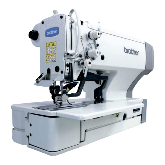
Brother HE-800A Instruction Manual
Electronic lockstitch button holer
Hide thumbs
Also See for HE-800A:
- Service manual (162 pages) ,
- Instruction manual (122 pages) ,
- User manual (118 pages)
Table of Contents
Advertisement
Advertisement
Table of Contents

Related Manuals for Brother HE-800A


Summary of Contents for Brother HE-800A
- Page 1 HE-800A ELECTRONIC LOCKSTITCH BUTTON HOLER...
-
Page 2: Safety Instructions
) indicates something that you must not do. This symbol ( ) indicates something that you must do. The picture inside the circle indicates the nature of the thing that must be done. (For example, the symbol at left means “you must make the ground connection”.) HE-800A... -
Page 3: Notes On Safety
Be sure to connect the ground. If the ground connec- Keep the oil out of the reach of children. tion is not secure, you run a high risk of receiving a serious electric shock, and problems with correct operation may also occur. HE-800A... -
Page 4: Maintenance And Inspection
Turn off the power switch before inserting or removing Any problems in machine operation which result from the plug, otherwise damage to the control box could unauthorized modifications to the machine will not be result. covered by the warranty. HE-800A... -
Page 5: Warning Labels
Do not touch any of the fan or press any objects against the machine, as this may result in personal injury or damage to the machine. Direction of operation Thread take-up cover Belt cover Eye guard Belt cover plate Finger guard 3852Q HE-800A... -
Page 6: Table Of Contents
7-2. Threading the upper thread ......58 4-14-1. Changing the treadle unit 7-3. Winding the lower thread ........59 installation position 7-4. Threading the bobbin case ......60 (horizontal positioning only) ....22 7-5. Thread tension..........61 4-15. Installing the spool stand......23 HE-800A... - Page 7 16-14. Unraveling of thread trimmed by upper 11. CHANGING FUNCTIONS USING thread trimmer assembly......101 16-15. Upper thread mis-trimming .......102 THE MEMORY SWITCHES ....16-16. Needle strikes upper thread trimmer ..102 11-1. Memory switch table ........79 16-17. Needle breakage ........103 HE-800A...
- Page 8 ........108 16-27. Needle does not zigzag or noise occurs when needle zigzags ........ 109 16-28. Sewing machine stops during sewing ..109 16-29. Upper shaft does not rotate as far as the needle up stop position....... 109 HE-800A...
-
Page 9: Name Of Each Part
(5) AC servo motor (6) Stop switch (7) Spool stand (8) Pulley (9) Tension release lever Safety devices (10) Eye guard (11) Thread take-up cover (12) Belt cover (13) Belt cover plate (14) Finger guard (15) Finger protector (16) Belt retainer HE-800A... -
Page 10: Specifications
Schmetz 134 Nm75 P-ROM (Custom made pattern can be added by the programming software for Data storage method electronic pattern sewer) Single phase 110 V, 220 V, 230 V Power supply Three phase 220 V, 380 V, 400 V 600 VA HE-800A... -
Page 11: Standard Sewing Pattern List
* [0] to [4] indicate the setting range for parameter No. 1. (Refer to "5-5. Parameter table".) * In addition to the above shapes, you can create and use up to 9 additional custom made patterns using the programming software for electronic pattern sewer. HE-800A... -
Page 12: Optional Parts
Needle plate set 1.4RB S51362-001 Needle plate set 1.6RB S51363-001 Needle plate set 1.2RB-3 S51364-001 Needle plate set 1.4RB-3 S51365-001 Needle plate set 1.6RB-3 S51366-001 2037Q 3-2. Leg parts Parts name Parts code Spacer set 183504-109 2038Q Caster set 183501-001 2039Q HE-800A... -
Page 13: Standing Operation Pedal
Two pedals + work clamp lifter pedal J80081-040 2040Q Three pedals J80380-040 2041Q Harness for standing operation pedal S47750-000 3854Q 3-4. Ruler Parts name Parts code Horizontal Ruler assy 800E S50350-001 ruler 2043Q Vertical Ruler assy S50477-001 ruler 2044Q HE-800A... -
Page 14: Tape Guard
You can use the icon keys to retrieve parameters at a single touch, and to display them as icons on the LED screen so that the settings can be changed easily. It allows you to easily transfer data between different sewing machines. 3855Q HE-800A... -
Page 15: Installation
If using a commercially-available table, process it as shown in the illustration below. Note: The thickness of the table should be at least 40 mm, and it should be strong enough to bear the weight and vibration of the sewing machine. [Vertical positioning] 2194Q HE-800A... -
Page 16: Installing The Motor
4. INSTALLATION [Horizontal positioning] 2195Q 4-2. Installing the motor Install the motor (1) with the three bolts (2), flat washers (3), spring washers (4) and nuts (5). 3856Q HE-800A... -
Page 17: Installing The Flange Nut
(9) as shown in the illustration. At this time, leave a gap of approximately 2 mm between the work table and the top of the box. 3. Close the covers (main P.C. board mounting plate (2) and sub P.C. mounting plate (3)), and provisionally tighten them with the screws (1). (They will be opened again when the cords are connected.) HE-800A... -
Page 18: Installing The Power Switch
2. Provisionally tighten the four flange nuts (4) onto the four bolts (3), and then position the bed base (1). 3. Install the bed base (1) with the three flat washers (5) and wood screws (6), and then install the two rubber caps (7). 4. Remove the four bolts (3). HE-800A... -
Page 19: Installing The Machine Head
Tap the head rest (1) into the table hole. Note: Tap the head rest securely into the table hole. If the head rest is not pushed in as far as it will go, the machine head will not be sufficiently stable when it is tilted back. 2778Q HE-800A... -
Page 20: Installing The Operation Panel
3. Install the oil stopper plate (2). 4. Move the connector cord (1) so that it will not be clamped by the machine head and the bed base (3), and then return the machine head to its original position. 3866Q HE-800A... -
Page 21: Connecting The Cords
2. Gently tilt back the machine head. 3. Pull the harness (1) through the cord clamp (2) at the top of the control box. * This cord clamp is not used when the machine head is positioned horizontally. 3868Q HE-800A... -
Page 22: Connecting The Motor Harness
Take note of how these two harnesses are routed through the control box so as not to confuse them with any of the other harnesses. Main P.C. board Harness Mark indication Zigzag motor P16 NPM <6-pin> Tension release (10) P19 OPSOL solenoid <6-pin> 3871Q HE-800A... -
Page 23: Connecting The Power Cord
2. Insert the plug into properly-grounded AC power supply. Note: • Do not use extension cord, otherwise machine operation problems may result. • Do not connect a power supply which is not of the rated voltage, otherwise machine operation problems may result. 4027Q HE-800A... -
Page 24: Connecting The Standing Operation Pedal Harness (Option)
(1) and re-tighten the screw (2). (The green-and-yellow wire is the ground wire.) 4. Connect the harness (4) to the standing operation pedal harness (1). * Connect the harness (4) and the standing operation pedal harness (1) inside the control box. HE-800A... -
Page 25: Installing The Transformer
2. Place the transformer on top of the two treadle support plates (3) as shown in the diagram, and then secure it to the handle (2) using the washers and screws. * The washers and screws must be obtained separately. Screw (M6 x 14) Washer 3876Q HE-800A... -
Page 26: Connecting The Cords
3. Secure the connected cords with the cord holder (5) and the screw (6), and place them inside the transformer cover (2). 4. Install the transformer cover (2) with the four screws (1). 5. Secure the cords to the work table using staples. HE-800A... -
Page 27: Installing The V-Belt
If any such problems occur, adjust by following the procedure described above. 4. Secure the motor belt cover (2) and the auxiliary motor belt cover (5) with the four screws (1) as shown in the illustration so that they do not touch the V-belt (3). 3884Q HE-800A... -
Page 28: Installing The Belt Cover Plate
Install the belt cover (1) with the two wood screws (3) so that it does not touch the motor belt cover (2). * Set the belt cover plate (1) so that there is a gap of 3 mm or more in the longer motor direction, and also should not be projected out from the edge of the work table. HE-800A... -
Page 29: Installing The Treadle Connecting Rod
Remove the nut (3), and then move connecting rod joint (7) from the position in figure A to the position in figure B. The treadle stroke will increase by approximately 1.25 times. * This adjustment will also affect the treadle pressure and the treadle return pressure, so these settings should be readjusted if necessary. HE-800A... -
Page 30: Changing The Treadle Unit Installation Position (Horizontal Positioning Only)
5. Install the treadle setting plate (5) and the treadle unit (1) to the motor with the three screws (4). 6. Install the ground wire with the screw (7). 7. Re-connect the connector (2) of the treadle unit (1) inside the control box. HE-800A... -
Page 31: Installing The Spool Stand
Install the eye guard (1) with the screw SM4.76-32x6 (2) and the flat washer (3). [Horizontal positioning] 1. Install the eye guard support (4) to the machine head with the screw (5). 2. Install the eye guard (6) with the screw SM4.76-32x6 (7) and the flat washer (8). HE-800A... -
Page 32: Lubrication
4. Gently return the machine head to its original position. * Periodically tilt back the machine head and check the lubricating oil level. If the oil level drops below the “LOW” mark, add more lubricating oil. * Replace the lubricating oil about once every six months. HE-800A... -
Page 33: Lubricating The Arm
Use Kraft paper (4) or similar to catch the oil drops. As a guide, the optimum position can be obtained if the adjusting screw (3) is tightened as Less much as possible and then loosened about two turns. 3900Q HE-800A... -
Page 34: Installing The Belt Cover
2. Insert the belt cover (2) in the direction of the arrow, and then secure it with the two screws (3), the screw (4) and the flat washer (5). Note: When tilting back the machine head, remove the screws (3), loosen the screw (4) and then remove the belt cover (2). HE-800A... -
Page 35: Operation
→ 1. P1 to P9 are programs that are created by the programming software for the electronic pattern sewer, and C1 to C9. are cycle programs. (7) Program No. UP key Press to increase the value in the program number LED. HE-800A... - Page 36 If you depress the treadle to start the sewing machine while the ENTER key is being pressed during automatic mode, only the sewing machine will operate and the mode will change to lower thread winding mode. HE-800A...
-
Page 37: Home Position Detection (Preparation)
* The sewing machine will move to the home position, and the work clamp will move to the neutral position. * After the home position has been reached, the mode will change to the mode which was active when the power was turned off (automatic/test feed/manual/program). HE-800A... -
Page 38: Operating The Treadle
No. 04. This is useful for inserting and removing the material. (Figure 5) * The work clamp rises while the treadle is being depressed backward, and it returns to the neutral position when the treadle is released. HE-800A... -
Page 39: Operating The Standing Operation Pedal (Option)
Work clamp lifter pedal 3908Q When circuit board DIP switch 2 - No. 3 is set to ON, you can set the work clamp to lower while the work clamp pedal is being depressed. HE-800A... -
Page 40: Program Setting Method
Note: The setting will not be changed if the ENTER key (5) is not pressed. 7. Press the SELECT key (1) to change the mode to automatic mode. The setting details can be saved in the pro-gram notes of the program memos for easy checking. (Refer to “5-12. Using the program memos”.) HE-800A... -
Page 41: Program Setting Examples
5. Press the parameter keys (5) and (6) to select the parameter setting value 3, and then press the ENTER key (4). 6. Press the SELECT key (1) to change the mode to automatic mode. A round buttonhole sewing pattern has now been set for program No. 03. 3911Q HE-800A... - Page 42 9. Press the parameter keys (5) and (6) to select the parameter setting value 3, and then press the ENTER key (4). An eyelet taper-tack buttonhole has now been set for program No. 10. 10. Press the SELECT key (1) to change the mode to automatic mode. 3915Q HE-800A...
-
Page 43: Checking The Length Of Knife
The stitch length will be automatically determined by the value for the length of the knife which has been set. Therefore, if the knife length is not set correctly, problems may occur, such as the bar tacking stitches being cut by the knife. HE-800A... -
Page 44: Parameter Table
6.0. Zigzag pitch 0.10 - 2.00mm 0.025 0.350 Zigzag width 1.0 - 3.0mm Knife X space -0.4 - 1.0mm Knife Y space 0.00 - 2.00mm 0.05 1.00 HE-800A... - Page 45 Knife X position alignment -0.5 - 0.5mm Knife Y position alignment -0.8 - 0.8mm Zigzag width ratio (at left) 0.30 - 0.70 0.01 0.50 Stitch type Whip (W): Purl (P): Rear tack Right zigzag stitch Left zigzag stitch Front tack 3919Q 3920Q HE-800A...
- Page 46 7.0 - 40.0mm 13.0 Straight bar tack pitch 0.2 - 2.0mm Straight bar tack width 1.5 - 6.0mm Running speed 1,000 - 3,000rpm 2,000 Running length 3.0 - 32.0mm 11.0 Running pitch 1.0 - 5.0mm Running width 0.5 - 3.0mm HE-800A...
- Page 47 0.05 - 1.00mm 0.05 0.30 Front tack width correction (except radial) -2.0 - 2.0mm No. of front tack stitch (radial) 5 - 11 stitches Taper tack length (taper tack) 1.0 - 5.0mm Front tack sideways correction (rectangle only) -1.0 - 1.0mm HE-800A...
- Page 48 Rear tack pitch (except radial, eyelet) 0.05 - 1.00mm 0.05 0.30 Rear tack width correction -2.0 - 2.0mm (except radial, eyelet) No. of rear tack stitch (radial, eyelet) 5 – 11 stitches Eyelet buttonhole radius (eyelet type only) 1.0 - 3.0mm HE-800A...
- Page 49 No. of stitches in Y direction for saw-shaped rear 1 - 5 stitches tack vector shape (When sewing saw-shaped rear tack stitches for rectangular buttonholes) Start backtack 0 - 6 stitches Start backtack width 0.5 - 3.0mm Start backtack pitch 0.10 - 0.80mm 0.05 0.30 HE-800A...
- Page 50 0 - 1 Saw-shaped underlays 0: No saw-shaped underlays 1: Front and rear tack 2: Rear tack only 3: Front tack only No. of rectangle underlays 0 - 9 Underlay speed 1,000 - 3,000rpm 2,000 Underlay feed pitch 0.5 - 6.0mm HE-800A...
- Page 51 1 - 5 stitches (Only for saw-shaped stitch with underlay) 2-cycle sewing 0: No double stitch 1: Double stitch 1:Double stitch 2:Crossed double stitch 2: Crossed double stitch No. of bar tacks sewn for 2-cycle sewing 1 - 2 HE-800A...
- Page 52 Sewing start tension apply timing -4 - 6 stitches Rear bar tack tension release timing -4 - 4 stitches Rear bar tack tension apply timing -4 - 4 stitches Front bar tack tension release timing -4 - 4 stitches HE-800A...
-
Page 53: Available Sewing Area
7.3 X 24.5 4.0 X 20.0 6.0 X 20.0 7.3 X 36.0 4.0 X 32.0 6.0 X 32.0 7.3 X 47.0 4.0 X 40.0 6.0 X 40.0 ∗ ∗ ON, ON, ON or OFF, ON, OFF or OFF, OFF, OFF HE-800A... -
Page 54: Setting The Knife Length
(Zigzag width ratio [at Spare Spare left]) does not become 0.2mm 0.2mm larger or smaller. Parameter number 26 See illustration. 1.6 mm (Front tack sideways 1.6 mm correction) parameter number 36 0.4mm (Rear tack sideways correction) become larger 3924Q smaller. HE-800A... - Page 55 A. Change the work clamp over to a larger work clamp. Alternatively, change the needle plate to one with a larger hole. Note: Be sure to change the setting for panel DIP switch B also. B. Set parameter number 17 (Running length) to a smaller value and then set the straight bar tack length. HE-800A...
-
Page 56: Rear Tack Vector Shape Programs
Setting range 3: Saw-shape This is effective for preventing dimples in the rear tack, without the need for underlay sewing. * The number of stitches for the saw-shape type of sewing is set by means of parameter Nos. 38 and 39. HE-800A... -
Page 57: Underlay Programs
▪ When sewing underlays, the number of bar tacking stitches will increase, so that thread breakages or broken needles may occur. To avoid such problems, reduce the number of underlays or drop the sewing speed. ▪ When underlays above are sewn together, the order of sewing is underlays sewn together → saw-shape underlays → rectangle underlays. HE-800A... -
Page 58: Cutter Operation
▪ It can also be used if the rough edges of the material block the buttonhole after the left and right zigzag stitches have been sewn. • The cutter operates immediately before the left zigzag stitch of the last cycle is sewn, and it operates again when the front tack of the last cycle is sewn. HE-800A... -
Page 59: Cycle Program
LED (4). Clearing the cycle program Program number "0" signifies a clear status. If "0" is set, the setting details for all subsequent steps will be cleared. If C1 is set to "0", the cycle program will be cleared. HE-800A... -
Page 60: Production Counter
4. Press the ENTER key (7). The production counter value will be accepted and the mode will return to automatic mode. * If you press the SELECT key (1) while the production counter value is still flashing, the mode will return to automatic mode without the production counter value being changed. HE-800A... -
Page 61: Bobbin Thread Counter
If you do so, additions can be removed using an eraser and the space can be re-used. The program notes are useful for recording what patterns have been entered into which programs. 3943Q HE-800A... -
Page 62: Adding Patterns Created Using The Programming Software For Electronic Pattern Sewer
Knife Y position alignment -0.8 - 0.8mm Running speed (Straight bar tack) 1,000 - 3,000rpm 2,000 Underlay speed 1,000 - 3,000rpm 2,000 Slow speed 500 - 1,500rpm Rear tack speed 500 - 4,000rpm 4,000 Front tack speed 500 - 4,000rpm 4,000 HE-800A... -
Page 63: Checking The Sewing Pattern
SELECT key (1) once more, the mode will change back to test feed mode. ▪ If you would like to stop checking before the operation has completed, press the RESET key (9). The sewing machine will move to the home position, and the work clamp will move to the neutral position. HE-800A... -
Page 64: Manual Mode
▪ If you would like to stop checking before the operation has completed, press the RESET key (7). The sewing machine will move to the home position, and the work clamp will move to the neutral position. HE-800A... -
Page 65: Correct Use
1. Loosen the set screw (1). 2. Insert the needle as far as it will go so that the groove is facing toward pulley. 3. Securely tighten the set screw (1). [At the time of shipment] Spec. Needle 134 Nm90 134 Nm75 3948Q HE-800A... -
Page 66: Threading The Upper Thread
3. Press the parameter UP key (9). * The needle bar will move to the right to make threading easier. 4. Press the RESET key (7). * The needle bar will move to the center position and the work clamp will rise. 3951Q HE-800A... -
Page 67: Winding The Lower Thread
Loosen the set screw (6) and move the bobbin wider tension bracket (7) up and down to adjust. Case A * For case A, move the bobbin winder tension bracket down, and for case B, move it upward. Case B 3956Q HE-800A... -
Page 68: Threading The Bobbin Case
2. Pass the thread though the slot (1) and then under the tension spring (2) and through the slot (3). 3. When sewing whip stitches, pull approximately 40 mm of thread out from the thread hole (4), and when sewing purl stitches, pull approximately 40 mm of thread out from thread hole (5). HE-800A... -
Page 69: Thread Tension
Purl stitch (seal stitch) Adjust by turning the adjusting screw (1) until the bobbin case drops gently by its own weight (0.05 - 0.15 N) while the thread end coming out of the bobbin case is held. 2813Q HE-800A... -
Page 70: Upper Thread Tension
Upper thread tension for purl stitches (with zigzag tension closed) When using a program that has purl stitches set, press the RESET key to lower the work clamp, and then take the measurement shown in the illustration. 2152Q HE-800A... -
Page 71: Thread Take-Up Spring Height
(2) is aligned with the index mark. Index mark The standard position for the arm thread guide (3) is when the clearance between it and the screw (4) is 0.5 mm as shown in the illustration. 0.5mm 3960Q HE-800A... -
Page 72: Sewing
The sewing machine will not operate during this time, even if the treadle is depressed. Press the ENTER key (4) to cancel the alarm. (Refer to “5-11. Bobbin thread counter”.) 3962Q HE-800A... -
Page 73: If The Stop Switch Is Pressed During Sewing
▪ Always turn off the power before changing any of the DIP switch settings. Any changes to the DIP switch positions will not be effective until the power is switched off and back on again. HE-800A... -
Page 74: If The Thread Breaks During Sewing
An alarm will sound while the error is being displayed, but if circuit board DIP switch 1 - No. 7 is set to ON, you can set the alarm to sound only three times. (Refer to “13. CHANGING FUNCTIONS USING THE DIP SWITCHES”.) HE-800A... -
Page 75: Thread Breakage Before Sewing Is Finished
* The thread will be trimmed and the work clamp will be raised. 5. Before carrying out the next sewing operation, press the CUTTER ON key (3) to enable cutter operation. 6. Return the program number to the previous number. HE-800A... -
Page 76: When Resuming Sewing In Test Feed Mode Or Manual Mode
Note: When step 4. is carried out, the mode cannot be returned to test feed mode or manual mode. 5. Press the parameter UP key (3) or the parameter DOWN key (4). * The "E-00" display will be cleared. 6. Depress the treadle to start sewing from the current position. HE-800A... -
Page 77: Cleaning And Maintenance
If you continue using the sewing machine while dust or thread scraps have built up, it may cause the work clamp lifter pulse motor to go out of step. 2159Q HE-800A... -
Page 78: Draining The Oil
40”) will be displayed and you will not be able to operate the sewing machine. 3970Q 9-4. Cleaning the eye guard Wipe the eye guard clean with a soft cloth. Note: Do not use solvents such as kerosene or thinner to clean the eye guard. 2162Q HE-800A... -
Page 79: Checking The Needle
Clean the length feed plate (1) if foreign materials such as shavings start getting onto the material. 1. Loosen the two bolts (2), and then remove the length feed plate (1). 2. Clean the underside of the length feed plate (1) and the needle plate (3). 3971Q HE-800A... -
Page 80: Standard Adjustments
6. Install the rubber cap (2). * Different gauges are used for each of the two specifications -2 and -3, so make sure that the gauge being used matches the specifications and application for the sewing machine being adjusted. 3972Q HE-800A... -
Page 81: Adjusting The Needle And Hook Timing
1. Set the sewing machine to the home position and then press the RESET key. 2. Loosen the screws (3) and move the rotary hook (4) forward or back until there is a clearance of 0.01 to 0.08 mm between the needle (1) and the hook point (2). HE-800A... -
Page 82: Adjusting The Inner Rotary Hook And Rotary Hook Holder Overlap
2. Loosen the two screws (4), and move the cutter holder (5) to adjust so that the clearance between the cutter and the needle bar (3) is 0.3 mm. * Check that the needle bar (3) does not touch the cutter when it moves sideways. 0.3 mm 3980Q HE-800A... -
Page 83: Adjusting The Upper Thread Trimming
(2) touch the work clamp (3), the work clamp lifter pulse motor may get out of step. * If the tilting of the work clamp (3) causes skipped stitches to occur when sewing material joints, use the accessory auxiliary sheet (4) as shown in the illustration. HE-800A... -
Page 84: Adjusting The Upper Thread Scissors Opening Timing
* If you would like the scissors to start opening earlier, make this clearance smaller. 3. Check that the upper thread scissors (2) open smoothly during feeding. Note: If the upper thread scissors (2) do not open smoothly, the upper thread scissors (2) may touch the cutter and needle breakage may occur. HE-800A... -
Page 85: Adjusting The Lower Thread Clamp Timing
* If the index mark (2) is not inside the mark (4) when 3990Q the sewing machine is started, and error code “E-02” will be displayed. Turn the machine pulley to move the index mark (2) to the correct position and then start the sewing machine. HE-800A... -
Page 86: Changing Functions Using The Memory Switches
* The memory switch setting will flash while it is being changed. 5. Press the ENTER key (2) to accept the new setting. * The memory switch setting will stop flashing and illuminate steadily. 6. Press the SELECT key (1) to change the mode to automatic mode. HE-800A... -
Page 87: Memory Switch Table
ON: Changes are prevented being changed OFF: Changes are allowed Memory switch No. 07. 08. 09. Neutral position Work clamp lowered ON position No. 08. Machine start ON position No. 09. Work clamp raised ON position No. 07. 2188Q HE-800A... -
Page 88: Program Initialization
3. When all parameters of the selected program have been initialized, “- -” will appear in the program number LED (2), and “- - - -“ will appear in the parameter display LED (3). Settings which are initialized Parameters 4. Set the feed mechanism to the home position. (Refer to “5-2. Home position detection (preparation)”.) HE-800A... -
Page 89: Changing Functions Using The Dip Switches
Display setting during automatic mode = production counter (Default: 0) 2-cycle sewing ON (All programs will be set to 2-cycle sewing regardless of the setting for parameter No. 55.) 2-cycle sewing OFF Upper thread breakage detection disabled Upper thread breakage detection enabled Programs disabled Programs enabled HE-800A... - Page 90 * If the programs are initialized when Nos. 3, 4 and 5 are set to OFF, OFF and ON respectively, the initial value for parameter No. 02 - Cutter size will be set to 6.0 mm. (Normal default value is 13.0 mm.) HE-800A...
-
Page 91: Circuit Board Dip Switches
ON/OFF Setting items Default Three warning beeps Continuous warning beep Zigzag motor energization is turned off during pauses or when a thread breakage occurs Zigzag motor energization is not turned off during pauses or when a thread breakage occurs HE-800A... - Page 92 During standing pedal operation, the work clamp lowers only while the work clamp pedal is being depressed. During standing pedal operation, the work clamp keeps lowering when the work clamp pedal is released. 100V, 110V specifications ON/OFF 200V, 220V, 230V, 380V, 400V specifications HE-800A...
-
Page 93: Error Code Table
Cutter home position sensor is off. 3. Check that connector P23 on the main P.C. board and connector P13 on the sub P.C. board are properly connected. 4. Check the operation of the cutter home position sensor monitor lamp. HE-800A... - Page 94 Use the programming device (the programming software for E-53 Multi-working knife error the electronic pattern sewer or a programmer) to delete multi- working knife operations. Overall cycle program stitch no. error E-54 Clear the cycle program to reset the error automatically. (Exceeds 3,000 stitches.) HE-800A...
- Page 95 3. Check that connectors P3 and P6 on the main P.C. board E-90 (Excessive load during sewing.) are properly connected. 4. Check that machine motor harness connector CN7 and power supply harness connector CN8 on the 1-step power supply circuit board are properly connected. HE-800A...
- Page 96 While pressing the ENTER key, press the RESET key. All parameters (00 to 69) for the program will then be initialized and the machine will switch to program mode. C. By initializing all programs Refer to "12-1. Initializing all programs". HE-800A...
-
Page 97: Gauge Parts List
<For -2 specification> S50663-001 (1.2 mmS) S50664-001 (1.4 mmS) S50665-001 (1.6 mmS) <For -3 specification> S51248-101 (1.2 mmS) S51249-101 (1.4 mmS) S51250-101 (1.6 mmS) For flat cutter Specifications S50321-001 (1.2 mmS) S50322-101 (1.2 mmS) Needle plate 151843-001 156612-001 Plastic plate HE-800A... - Page 98 S01466-201 (16 mm) S01467-201 (25 mm) S55349-001 (25 mmW) S01468-201 (32 mm) 159079-000 159080-000 159080-000 159081-000 145136-001 144630-001 S55348-001 144632-001 Sewing area 4 × 20 Sewing area 4 × 32 Sewing area 5.4 × 32 Sewing area 5.4 × 40 HE-800A...
- Page 99 15. GAUGE PARTS LIST Cutter S51117-001 S51290-001 S51351-001 S51352-001 S51353-001 S51354-001 7/16 9/16 S51355-001 S51356-001 S25642-001 S51357-001 S51358-001 11/16 13/16 S51359-001 S51360-001 S01271-001 S01272-001 7/16 S01273-001 S03280-001 S01274-001 S01275-001 S01276-001 S35630-001 9/16 HE-800A...
-
Page 100: Troubleshooting
Loosen the thread take-up spring tension or shorten Thread take-up Thread take-up spring the stroke to such a degree that does not cause spring tension and stroke double hooking. Adjust it while checking bar tacking stitches. HE-800A... -
Page 101: Skipped Stitches
Upper thread amount Arm thread guide position Adjust the arm thread guide position Bobbin case Damaged outside Polish with buff or replace the part. bobbin case and bent * Use the HE-800A bobbin case. bobbin holder spring, etc. 16-2. Skipped stitches Cause Check Remedy Page... -
Page 102: Uneven Seams
Apply grease to the inclined face of the opening operation cam. Upper thread feeding Thread take-up amount Loosen the screw to decrease thread take-up amount so that upper thread does not pull out of scissors assembly at the sewing start. Screw Increase Decrease 4000Q HE-800A... -
Page 103: Uneven Seams
6 – 7 mm. Lower thread clamping If the lower thread clamp and lower thread presser force are bent, replace them. Check that the screws are tightened. Screw Lower thread clamp 3999Q HE-800A... -
Page 104: Uneven Seams
Adjust the tension disc opening amount. tension opening Check the opening of the zigzag tension discs. Replace the tension release solenoid. Upper thread Upper thread scissors Apply grease to the inclined face of the opening scissors operation cam. HE-800A... -
Page 105: Uneven Seams
* Setting the vector shape to a rectangle can be effective when the width is less than the bar tack width. Needle plate Needle plate When using knit material, replace with the –3 needle plate. Replace with a needle plate with a smaller needle hole. HE-800A... -
Page 106: Uneven Seams
Adjust the lower thread tension. Bobbin case Damaged outside Polish with buff or replace the part. bobbin case and bent * Use the HE-800A bobbin case. bobbin holder spring, etc. Stitch patterns Purl stitch, whip stitch Set using parameter number 11. HE-800A... -
Page 107: Upper Thread Run Out
Adjust the bar tack tension discs opening amount to 0.5 - 1.0 mm by removing the top cover and moving the tension release cam. Zigzag tension Tack tension 0.5 - 1 mm 4008Q HE-800A... - Page 108 Use parameter number 59 to increase the number of slow start stitches. tack thread Bar tack thread tension is Make the bar tack tension as weak as possible. tension too strong. Upper thread Upper thread breaks. Refer to “16-1. Upper thread breakage”. 92, 93 breakage HE-800A...
-
Page 109: Unraveling Of Thread Trimmed By Upper Thread Trimmer Assembly
0.5 - 1.0 mm by removing the top cover and tension discs) moving the tension release cam. Zigzag tension Tack tension 0.5 - 1 mm 4008Q Work clamp Work clamp lifting speed Use memory switch No. 02 to retard the work clamp lifting speed. HE-800A... -
Page 110: Upper Thread Mis-Trimming
Upper thread trimmer cutting depth adjustment Service manual 4005Q upper thread trimmer Remove any scratches and burrs, and adjust the upper thread trimmer M to open when the projection operating force is pressed with a force of 4N or less. 4010Q HE-800A... -
Page 111: Needle Breakage
Adjust the gap between needle and rotary hook to rotary hook 0.01 - 0.08 mm. (Adjust to as large as possible without causing skipped stitches to occur.) * Check that rotary hook point does not strike needle in zigzag motion. HE-800A... -
Page 112: Imperfect Cutter Function (Imperfect Material Cutting)
Tighten any loose screws. Loose screws Cutter solenoid Check for a disconnected Connect the cords. cord. Cutter power Memory switches If the material is heavy and difficult to cut, use memory switch No. 00 to increase the cutting force of the cutter. HE-800A... -
Page 113: Cutter Does Not Return
Use parameter number 08 to set the knife X position alignment. Cutter Cutter play Adjust the cutter bar guide so that the cutter operates smoothly with no play. Cutter knife bending Use the cutter holder (option) to prevent the cutter knife from becoming bent. 4019Q HE-800A... -
Page 114: Upper Thread Mis-Winding
Check if the drive gear screw is loose. driving gear Treadle Does the work clamp rise If it rises, use memory switch No. 08 to adjust the when treadle threshold value for lowering the work clamp to a depressed backward? positive value. HE-800A... -
Page 115: Work Clamp Is Not Raised (2) Pulse Motor Stepping Sound Can Be Heard
* If the lower thread tension is too strong, the motor may go out of step. Use memory switch No. 02 to reduce the work clamp lifting speed setting to make the lifting speed slower. Buff this section to reduce the thread retaining resistance. 4023Q HE-800A... -
Page 116: Lower Thread Is Not Trimmed (Pulls When Material Is Removed)
4025Q Check if the cam opens Adjust the cam position. the stop plate. * If the feed mechanism operates when the cam has not opened the stop plate, the cutter will bump against the upper thread scissors. 4018Q HE-800A... -
Page 117: Needle Does Not Zigzag Or Noise Occurs When Needle Zigzags
Thread trimmer rotary hook mechanism position needle bar to the needle up position. touching. Push the thread driving arm in the direction of the arrow to set the thread trimming mechanism to the home position. Thread driving arm 4026Q HE-800A... -
Page 118: Instruction Manual
INSTRUCTION MANUAL □ http://www.brother.com/ HE-800A SA2978-001 2003.12.B(2)
Need help?
Do you have a question about the HE-800A and is the answer not in the manual?
Questions and answers
Button hole left side cutt what's problem
Kaj khife setting