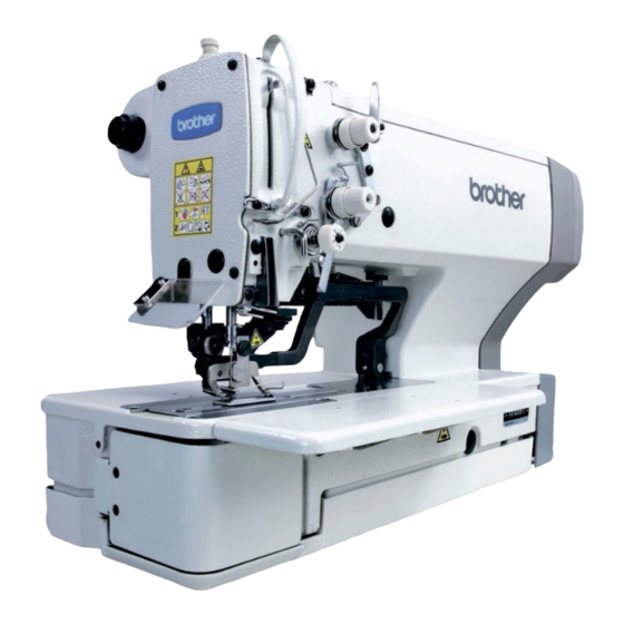
Brother HE-800A User Manual
Electronic lockstitch button holer
Hide thumbs
Also See for HE-800A:
- Service manual (162 pages) ,
- Instruction manual (122 pages) ,
- Parts manual (80 pages)
Table of Contents
Advertisement
Advertisement
Table of Contents

Related Manuals for Brother HE-800A


Summary of Contents for Brother HE-800A
- Page 1 HE-800A ELECTRONIC LOCKSTITCH BUTTON HOLER...
-
Page 2: Safety Instructions
Thank you very much for buying a BROTHER sewing machine. Before using your new machine, please read the safety instructions below and the explanations given in the instruction manual. With industrial sewing machines, it is normal to carry out work while positioned directly in front of moving parts such as the needle and thread take-up lever, and consequently there is always a danger of injury that can be caused by these parts. - Page 3 Furthermore, do not excessively bend the cords or secure them too firmly Contact your Brother dealer or a qualified electrician with staples, otherwise there is the danger that fire or for any electrical work that may need to be done.
-
Page 4: Maintenance And Inspection
Ask your Brother dealer or a qualified electrician to carry out any maintenance and inspection of the Use both hands to hold the machine head when tilting electrical system. - Page 5 The following warning labels appear on the sewing machine. Please follow the instructions on the labels at all times when using the machine. If the labels have been removed or are difficult to read, please contact your nearest Brother dealer. NOTE: Either the 2a or the 2b label is displayed on the sewing machine.
- Page 6 Thread take-up cover Belt cover Eye guard Belt cover plate Finger guard 4404M HE-800A...
-
Page 7: Table Of Contents
CONTENTS 1. NAME OF EACH PART......5. OPERATION......... 5-1. Name and function of each operation panel item..27 2. SPECIFICATIONS ........ 5-2. Home position detection (preparation)....29 2-1. Specifications ..........2 5-3. Operating the treadle ........30 2-2. Standard sewing pattern list ......3 5-3-1. - Page 8 16-4. Uneven seams (2) …… 9.CLEANING AND MAINTENANCE ..Lower thread is lifted up at 9-1. Cleaning ............69 the sewing start .........95 9-2. Draining the oil..........70 16-5. Uneven seams (3) …… 9-3. Cleaning the control box air inlet port..... 70 Seam lifts up at the sewing start....96 9-4.
-
Page 9: Name Of Each Part
1. NAME OF EACH PART . NAME OF EACH PART 4110M (1) Power switch (2) Control box (3) Operation panel (4) Treadle (5) AC servo motor (6) Stop switch (7) Spool stand (8) Pulley (9) Tension release lever Safety devices (10) Eye guard (11) Thread take-up cover (12) Belt cover... -
Page 10: Specifications
2. SPECIFICATIONS . SPECIFICATIONS - . Specifications Main use Buttonhole size Buttonholes for clothing such as dress shirts, blouses, work clothes and women's clothes Buttonholes for knitted garments such as knitted underwear, sweaters, cardigans and jerseys A: Max.6 mm B: Max. zigzag stitch length 39 mm C: Length of knife 4 –... -
Page 11: Standard Sewing Pattern List
2. SPECIFICATIONS - . Standard sewing pattern list [1] Rectangle [2] Radial [3] Round [4] Straight bar tack Rear tack tack Front [0] Free (Combinations of rear tack shapes and the front tack shapes - 17 patterns) Radial-rectangle Round-rectangle Eyelet-rectangle Rectangle-radial Round-radial Eyelet-radial... -
Page 12: Optional Parts
3. OPTIONAL PARTS . OPTIONAL PARTS - . Special needle plate This needle plate uses the elasticity of rubber to prevent the cutter from getting stuck and not returning. It also helps to keep the cutter blade sharp. * The standard cutter can be used. Parts name Parts code Needle plate set 1.2RB... -
Page 13: Standing Operation Pedal
3. OPTIONAL PARTS - . Standing operation pedal Parts name Parts code <Except for Europe> J80380-040 Three pedals <For Europe only> J80380-0E0 2041Q Harness for standing operation pedal S47750-000 3854Q - . Ruler Parts name Parts code Horizontal Ruler assy 800E S50350-001 ruler 2043Q... -
Page 14: Tape Guard
3. OPTIONAL PARTS - . Tape guard Tape guard winder assy S50346-001 Tape winder assy 143767-102 Tape guard assy S51896-001 2042Q HE-800A... -
Page 15: Installation
Furthermore, do not excessively bend the cords or secure them too Contact your Brother dealer or a qualified firmly with staples, otherwise there is the danger electrician for any electrical work that may need that fire or electric shocks could occur. -
Page 16: Installing The Motor
4. INSTALLATION [Horizontal positioning] 4095M - . Installing the motor Install the motor (1) with the three bolts (2), flat washers (3), spring washers (4) and nuts (5). 3856Q HE-800A... -
Page 17: Installing The Flange Nut
4. INSTALLATION - . Installing the flange nut Install the four flange nuts (1) to the underside of the work table. Note: When the machine head is positioned horizontally, some flange nut installation locations may be inaccessible after the control box has been installed. 3857Q - . -
Page 18: Installing The Power Switch
4. INSTALLATION - . Installing the power switch 1. Install the power switch (1) with the two screws (2). 2. Secure the power switch (1) cord and the motor (4) cord with the six staples (3). 3859Q - . Installing the bed base 4069M 1. -
Page 19: Installing The Machine Head
4. INSTALLATION - . Installing the machine head 3861Q 1. Place the two bed hinges (1) so that they are level as shown in the illustration at left, and then place the machine head gently on top of the bed base (3) so that the cables (2) do not get clamped. -
Page 20: Installing The Operation Panel
4. INSTALLATION - . Installing the operation panel 3863Q The operation panel can be installed to either the top Top of work table or bottom of the work table. 1. Install the rear frame (1) to the work table (top or bottom) with the four wood screws (2). -
Page 21: Connecting The Cords
4. INSTALLATION . Connecting the cords The harness is connected in the same way regardless of whether the machine head is positioned horizontally or vertically. - . Connecting the ground wire CAUTION Be sure to connect the ground. If the ground connection is not secure, you run a high risk of receiving a serious electric shock, and problems with correct operation may also occur. -
Page 22: Connecting The Motor Harness
4. INSTALLATION - . Connecting the motor harness 1. Pass the motor harness (1) through the cord bush (2). 2. Connect the connectors (3). 3. Secure the motor harness (1) with staples. 3869Q 4. Securely insert each of the connectors (4) – (8) as indicated below. -
Page 23: Connecting The Power Cord
4. INSTALLATION 6. Securely insert each of the connectors (11) – (13) as indicated below. Harness Mark Main P.C. board indication (11) Synchronizer <5-pin> P3 SYNC Home position sensor (12) P11 ORG <12-pin> (13) Stop switch <11-pin> P10 HEAD 7. Secure the harnesses inside the control box using cord clamps as shown in the illustration. -
Page 24: Connecting The Standing Operation Pedal Harness (Option)
4. INSTALLATION - . Connecting the standing operation pedal harness (option) 4111M 1. Pass the marked tube of the standing operation pedal harness (1) into the control box through the hole in the control box. 2. Connect the standing operation pedal harness (1) to connector P9 on the main circuit board. 3. -
Page 25: Installing The Transformer
4. INSTALLATION - . Installing the transformer The transformer can be installed on the floor, on the work table leg (on top of the leg or on the treadle support plates) or underneath the work table. Check the power supply rating label on the transformer to confirm that the voltage ratings for the transformer and the control box are identical. - Page 26 3877Q 3879Q Standard BROTHER work tables are provided with installation holes for use in installing the transformer. 1. Remove the four screws (1), and then remove the two handles (2). 2. Use the bolts (4), flat washers (5), spring washers (6) and nuts (7) to install the transformer as shown in the illustration, while leaving a gap of 2 mm between the work table and the cushion collars (3).
-
Page 27: Installing The V-Belt
4. INSTALLATION . Installing the V-belt 3882Q 1. Remove the four screws (1), and then remove the motor belt cover (2). 2. Gently tilt back the machine head, and then place the V-belt (3) into the V grooves in the machine head pulley and the motor pulley. -
Page 28: Installing The Belt Cover Plate
4. INSTALLATION Adjusting the belt holder 1. Loosen the screw (1). 2. Align the boss of the belt holder (2) with the mark (3). 3. After adjusting, tighten the screw (1). Adjusting the finger protector 1. Loosen the screw (4). 2. -
Page 29: Installing The Treadle Connecting Rod
4. INSTALLATION . Installing the treadle connecting rod Install the connecting rod (1) to the treadle lever (2) with the nut (3). 3888Q Fig. A Fig. B 3889Q 3890Q Adjusting the treadle pressure If the machine starts running when your foot is simply resting on the treadle, or if the treadle pressure is too weak, adjust the position (a to c) at which the treadle spring (4) is hooked onto the treadle lever (2). -
Page 30: Changing The Treadle Unit Installation Position (Horizontal Positioning Only)
4. INSTALLATION - . Changing the treadle unit installation position (horizontal positioning only) Note: If the machine head is positioned horizontally, install the treadle unit to the motor. 3891Q 3892Q 3893Q 1. Disconnect the connector (2) of the treadle unit (1) inside the control box. 2. -
Page 31: Installing The Spool Stand
4. INSTALLATION . Installing the spool stand Assemble the spool stand (1) while referring to the spool stand instruction manual, and then install the spool stand (1) at the left side of the work table. 4112M . Installing the eye guard CAUTION Attach all safety devices before using the sewing machine. -
Page 32: Lubrication
Use only the lubricating oil <NIPPON OIL CORPORATION Sewing Lube 10N; VG10> specified by Brother. * If this type of lubricating oil is difficult to obtain, the recommended oil to use is <Exxon Mobil Essotex SM10; VG10>. -
Page 33: Lubricating The Arm
4. INSTALLATION - . Lubricating the arm Apply 5-6 drops of oil to the oil inlet (1) at the top of the arm. * When using the machine, check that the oil is visible through the oil window (2). If it cannot be seen, problems such as seizure of the mechanism may occur. -
Page 34: Installing The Belt Cover
4. INSTALLATION . Installing the belt cover Clearances should be the same 4098M 1. Install the belt cover D plate (2) to belt cover D (1). 2. Provisionally install belt cover D (1) to the table with the two screws (3). 3. -
Page 35: Operation
5. OPERATION . OPERATION - . Name and function of each operation panel item 3902Q (1) Power indicator Illuminates when the power is turned on. (2) Warning indicator Illuminates when an error occurs, and after the RESET key is pressed to lower the work clamp but the needle is not at the up stop position when the machine pulley turns. - Page 36 5. OPERATION (8) Program No. DOWN key Press to decrease the value in the program number LED. (9) Automatic mode indicator Illuminates during automatic mode. The normal sewing mode is when the automatic mode indicator is illuminated. (10) Test feed mode indicator Illuminates during test feed mode.
-
Page 37: Home Position Detection (Preparation)
5. OPERATION - . Home position detection (preparation) Before starting home position detection, check that the needle bar is at its highest position. Turn the machine pulley so that the index mark (1) on the pulley is inside the mark (2) on the belt cover. If the machine is started while the index mark (1) is not inside the mark (2), error message "E-02"... -
Page 38: Operating The Treadle
5. OPERATION - . Operating the treadle 3906Q After sewing Fig. 2 Fig. 5 Fig. 1 Fig. 3 Fig. 4 Insertion and removal of Normal position Buttonhole positioning Sewing the material 1. When the treadle is not depressed [A], the work clamp is at the neutral position. (Figure 1) * The work clamp lifter height at the neutral position can be changed to between 1 mm and 13 mm using memory switch No. -
Page 39: Operating The Standing Operation Pedal (Option)
5. OPERATION - - . Operating the standing operation pedal (option) Note: Set the circuit board DIP switch 2 - No.1 to ON. (Refer to “13. CHANGING FUNCTIONS USING THE DIP SWITCHES”.) Three pedals When the work clamp pedal (middle) is depressed, the work clamp lowers, and when it is depressed once more, the work clamp returns to the neutral position. -
Page 40: Program Setting Method
5. OPERATION - . Program setting method The parameters for program numbers 1 to 90 are all set to their default values at the time of shipment. (Refer to “5-5. Parameter table”.) 3909Q 1. Press the SELECT key (1) to change the mode to automatic, test feed or manual mode. 2. -
Page 41: Program Setting Examples
5. OPERATION - - . Program setting examples Example 1: How to make a buttonhole (round) setting for program number 3. 3910Q Set parameter number 01 to "buttonhole stitch (round) setting value 3". 1. Press the SELECT key (1) to change the mode to automatic, test feed or manual mode. - Page 42 5. OPERATION Example 2: How to set a taper tack for the front tack pattern and an eyelet for the rear tack pattern to program number 3912Q First, set parameter number 01 to "buttonhole stitch (free) setting value 0". 1. Press the SELECT key (1) to change the mode to automatic, test feed or manual mode.
-
Page 43: Checking The Length Of Knife
5. OPERATION Example 3: How to copy the settings for program No. 3 to program No. 11. 3916Q Set parameter number 69 to "Copy source program number setting value 3". Press the SELECT key (1) to change the mode to automatic, test feed or manual mode. -
Page 44: Parameter Table
5. OPERATION - . Parameter table The parameter values can be stored independently for each program. The allowable setting range for some parameters may vary from the range specified, depending on the settings of other parameters. (Refer to “5-5-4. Main restrictions when setting parameters”.) •... - Page 45 5. OPERATION Setting items Setting range Unit Default Knife X position alignment -0.5 - 0.5mm Knife Y position alignment -0.8 - 0.8mm Zigzag width ratio (at left) 0.30 - 0.70 0.01 0.50 Stitch type Whip (W): Purl (P): Rear tack Right zigzag stitch Left zigzag stitch Front tack...
- Page 46 5. OPERATION * Nos. 13 to 19 are for straight bar tacks. Setting items Setting range Unit Default Straight bar tack length 7.0 - 40.0mm 13.0 Straight bar tack pitch 0.2 - 2.0mm Straight bar tack width 1.5 - 6.0mm Running speed 1,000 - 3,000 sti/min 2,000...
- Page 47 5. OPERATION Setting items Setting range Unit Default Front tack pattern 0: Rectangle 1: Radial 2: Round 3: Tack 4: Taper tack Rectangle Radial Round Tack Taper tack Front tack length (except taper tack) 0.5 - 5.0mm Front tack pitch (except radial) 0.05 - 1.00mm 0.05 0.30...
- Page 48 5. OPERATION Setting items Setting range Unit Default Rear tack pattern 0: Rectangle 1: Radial 2: Round 3: Eyelet Radial Round Eyelet Rectangle Rear tack length (except eyelet) 0.5 - 5.0mm Rear tack pitch (except radial, eyelet) 0.05 - 1.00mm 0.05 0.30 Rear tack width correction...
- Page 49 5. OPERATION Setting items Setting range Unit Default Rear tack sideways correction (rectangle only) -1.0 - 1.0mm Rear tack vector shape(rectangle only) 1: Triangle 2: Rectangle 3: Saw-shape No. of stitches in X direction for saw-shaped rear 2 - 14 stitches tack vector shape (When sewing saw-shaped rear tack stitches for rectangular buttonholes) No.
- Page 50 5. OPERATION Setting items Setting range Unit Default End backtack 1 - 6 stitches Cutter operation 0: Operates when the front tack of the last cycle is sewn (standard) 1: Operates when sewing is finished material feeding. 2: Operates immediately before the left zigzag stitch of the last cycle is sewn.
- Page 51 5. OPERATION Setting items Setting range Unit Default Underlay offset 0.3 - 1.0mm Underlay sewing start length 2.0 - 10.0mm Underlay sewing start pitch 0.2 - 2.0mm Saw-shaped underlay bar tack X stitch no. 2 - 14 stitches (Only for saw-shaped stitch with underlay) Saw-shaped underlay bar tack Y stitch no.
- Page 52 5. OPERATION Setting items Setting range Unit Default First offset for 2-cycle sewing 0.0 - 0.8mm Zigzag underlay stitch width 0.0 - 3.0mm Slow start stitches 0 - 4 stitches Slow speed 500 - 1,500 sti/min Rear tack speed 500 - 4,000 sti/min 4,000 Front tack speed 500 - 4,000 sti/min...
-
Page 53: Available Sewing Area
5. OPERATION Setting items Setting range Unit Default Sewing end tension apply timing -5 - 0 stitches Rear tack width (rectangle only) OFF: Condense stitch 0.1 - 1.5mm OFF: Condense stitch 0.1 - 1.5mm (Normally set to 1.0) Program copy OFF, 1 –... -
Page 54: Setting The Knife Length
5. OPERATION - - . Setting the knife length Set parameter number 02 to the knife length that matches the cutter being used. (Refer to "5-4-2. Checking the length of knife".) Be sure to change the knife length setting if the knife is replaced with a knife of a different length. The stitch length will be automatically determined by the value for the length of the knife which has been set. - Page 55 5. OPERATION Symptom Cause Remedy Parameter number 35 If the sewing area is 4.0 mm and parameter 4.0 mm (Eyelet buttonhole number 06 (Knife X space) is set to 0.4 mm radius) does and parameter number 05 (Zigzag width) is set become larger to 1.5 mm, the eyelet buttonhole radius that...
-
Page 56: Rear Tack Vector Shape Programs
5. OPERATION - . Rear tack vector shape programs Parameter No. 37 1: Triangle 2: Rectangle 3: Saw-shape 3928Q 3929Q 3930Q Setting range 1: Triangle General sewing Setting range 2: Rectangle This is effective for preventing the material from getting stuck in the needle hole when sewing the rear tack, which can happen when using lightweight materials. -
Page 57: Underlay Programs
5. OPERATION - . Underlay programs Four types of underlay patterns are available. These four types can also be combined. Refer to the examples of use to determine which type of underlay to use. Parameter No. Underlays sewn together Saw-shape underlays Rectangle underlays Zigzag underlay stitch 3931Q... -
Page 58: Cutter Operation
5. OPERATION - . Cutter operation The cutter operating pattern can be selected from the following four patterns. Parameter No. 44 Operates when the front Operates near the front Operates immediately Operates twice: tack of the last buttonhole tack when sewing before the left zigzag stitch immediately before the left... -
Page 59: Cycle Program
5. OPERATION - . Cycle program Cycle program can contain up to a maximum of nineteen steps. C3 …… C1. …… This section shows an example where C1 is set to program number 3 and C2 is set to program number 10. Step Program No. -
Page 60: Production Counter
5. OPERATION . Production counter Check that panel DIP switch A - No.4 is at the OFF setting. (Refer to “13. CHANGING FUNCTIONS USING THE DIP SWITCHES”.) 3941Q 1. Press the SELECT key (1) to change the mode to automatic mode. 2. -
Page 61: Bobbin Thread Counter
5. OPERATION . Bobbin thread counter If you use the bobbin thread counter to set the number of articles which can be sewn with the amount of bobbin thread available, you can stop the bobbin thread running out in the middle of sewing a pattern. Check that panel DIP switch A - No.4 is at the ON setting. -
Page 62: Adding Patterns Created Using The Programming Software For Electronic Pattern Sewer
5. OPERATION . Adding patterns created using the programming software for electronic pattern sewer You can use the programming software for electronic pattern sewer to create your own sewing patterns. Up to nine of the patterns which you create in this way can be programmed into a P-ROM. DANGER Wait at least 5 minutes after turning off the power switch and disconnecting the power cord from the wall outlet before opening the face plate of the control box. -
Page 63: Checking The Sewing Pattern
6. CHECKING THE SEWING PATTERN . CHECKING THE SEWING PATTERN You can check the sewing pattern which has been programmed, and also the needle zigzagging and feed operation. Checking can be carried out using test feed mode, or by turning the machine pulley by hand in manual mode. These two modes can also be combined in order to carry out checking. -
Page 64: Manual Mode
6. CHECKING THE SEWING PATTERN - . Manual mode 3947Q 3905Q 1. Press the SELECT key (1) to change the mode to automatic mode. 2. Press the program No. keys (2) and (3) to select the number for the program to be checked, and then press the ENTER key (4). -
Page 65: Correct Use
7. CORRECT USE . CORRECT USE CAUTION Turn off the power switch before installing the needle, otherwise the machine may operate if the treadle is depressed by mistake, which could result in injury. - . Installing the needle Use a Schmetz Nm 134 needle. 1. -
Page 66: Threading The Upper Thread
7. CORRECT USE - . Threading the upper thread CAUTION Turn off the power switch before threading the thread, otherwise the machine may operate if the treadle is depressed by mistake, which could result in injury. For threads which do not slide easily Thread will get caught For spun thread and For polyester thread... -
Page 67: Winding The Lower Thread
7. CORRECT USE - . Winding the lower thread CAUTION Do not touch any of the moving parts or press any objects against the machine while winding the lower thread, as this may result in personal injury or damage to the machine. 3952Q 3953Q 3954Q... -
Page 68: Threading The Bobbin Case
7. CORRECT USE - . Threading the bobbin case CAUTION Turn off the power switch before removing or inserting the bobbin case, otherwise the machine may operate if the treadle is depressed by mistake, which could result in injury. Purl stitch Whip stitch (seal stitch) (plain stitch) -
Page 69: Thread Tension
7. CORRECT USE - . Thread tension The shapes of the seams for all patterns which have been stored in programs 1 to 90 can be set using parameter No. 11. Make the following adjustments in accordance with the seam shape which has been set. [Stitch patterns] Whip stitch (plain stitch) Purl stitch (seal stitch) -
Page 70: Upper Thread Tension
7. CORRECT USE - - . Upper thread tension Zigzag stitch Bar tacking stitch 1280Q 3957Q Whip stitch (plain stitch) Turn the tack tension control (1) to adjust the thread tension so that a clean whip stitch is obtained at the bar tacking areas and the zigzag areas. -
Page 71: Thread Take-Up Spring Height
7. CORRECT USE - - . Thread take-up spring height Loosen the set screw (1), and turn the entire thread tension adjuster to adjust the thread take-up spring height to between 4 - 6 mm in accordance with the material to be sewn. 3958Q - - . -
Page 72: Sewing
8. SEWING . SEWING CAUTION Turn off the power switch at the following times, otherwise the machine may operate if the treadle is depressed by mistake, which could result in injury. When threading the needle When replacing the bobbin and needle When not using the machine and when leaving the machine unattended Do not touch any of the moving parts or press any objects against the machine while sewing, as this may result in personal injury or damage to the machine. -
Page 73: If The Stop Switch Is Pressed During Sewing
8. SEWING - . If the stop switch is pressed during sewing When the stop switch (1) is pressed, the sewing machine will stop and "E-00" will appear in the parameter display LED (2). 4101M 3964Q To finish sewing in this condition [Next sewing] 1. -
Page 74: If The Thread Breaks During Sewing
8. SEWING - . If the thread breaks during sewing When the thread breakage detector operates, the sewing machine will stop and "E-01" will appear in the parameter display LED (1). Re-thread the thread. 3965Q To finish sewing in this condition [Next sewing] 1. -
Page 75: Thread Breakage Before Sewing Is Finished
8. SEWING - . Thread breakage before sewing is finished If the thread breaks just before sewing is complete, and then sewing is completed without the thread breakage being detected, the following operations are possible. Note: This is enabled when panel DIP switch A - No. 1 is set to ON. Even if sewing is complete, leave the work clamp lowered and check the sewing. -
Page 76: When Resuming Sewing In Test Feed Mode Or Manual Mode
8. SEWING - . When resuming sewing in test feed mode or manual mode If the thread breaks during sewing and sewing finishes without the broke thread being detected, you can operate the sewing machine in test feed mode or manual mode until the needle zigzagging and material feed reach the point where sewing was interrupted, and then complete the rest of the sewing. -
Page 77: Cleaning And Maintenance
9. CLEANING AND MAINTENANCE . CLEANING AND MAINTENANCE CAUTION Turn off the power switch before carrying out cleaning, otherwise the machine may operate if the treadle is depressed by mistake, which could result in injury. Be sure to wear protective goggles and gloves when handling the lubricating oil and grease, so that they do not get into your eyes or onto your skin, otherwise inflammation can result. -
Page 78: Draining The Oil
9. CLEANING AND MAINTENANCE - . Draining the oil 1. Remove the belt cover, and then gently tilt back the machine head. Bed base 2. Place the oil tank (1) against the underside of the table, and then remove the screw (2). 3. -
Page 79: Checking The Needle
9. CLEANING AND MAINTENANCE - . Checking the needle Always check that the tip of the needle is not broken and also the needle is not bent before starting sewing. 2163Q - . Cleaning the length feed plate Clean the length feed plate (1) if foreign materials such as shavings start getting onto the material. -
Page 80: Standard Adjustments
If only one hand is used, the weight of the machine head may cause your hand to slip, and Ask your Brother dealer or a qualified electrician your hand may get caught. to carry out any maintenance and inspection of the electrical system. -
Page 81: Adjusting The Needle And Hook Timing
10. STANDARD ADJUSTMENTS - . Adjusting the needle and hook timing 3974Q Mark Lowest position 2168Q 2837Q 3973Q 1. Set the sewing machine to the home position and then press the RESET key. 2. Loosen the two screws (2) of the rotary hook joint (1). 3. -
Page 82: Adjusting The Inner Rotary Hook And Rotary Hook Holder Overlap
10. STANDARD ADJUSTMENTS - . Adjusting the inner rotary hook and rotary hook holder overlap Loosen the two screws (3) to adjust so that the tip of the rotary hook holder (1) does not protrude past the edge A of the inner rotary hook (2). 3977Q - . -
Page 83: Adjusting The Upper Thread Trimming
10. STANDARD ADJUSTMENTS - . Adjusting the upper thread trimming The standard distance (A) between the upper thread scissors (1) and the center of the needle is 5.5 to 6.0 mm when the work clamp is lowered by pressing the RESET key after setting the machine to the home position. -
Page 84: Adjusting The Upper Thread Scissors Opening Timing
10. STANDARD ADJUSTMENTS - - . Adjusting the upper thread scissors opening timing After setting the sewing machine to the home position, press the RESET key and then make the adjustment. 4104M 4105M Start touching at 1.5 - 2.5 mm Start touching at 1.5 –... -
Page 85: Adjusting The Lower Thread Clamp Timing
10. STANDARD ADJUSTMENTS - . Adjusting the lower thread clamp timing When reference line A on feed guide shaft B (1) is aligned with the edge of the feed arm support (2), the opening plate (3) will start moving when the feed mechanism moves 6 - 7 mm from the home position, and the lower thread retainer (4) will open. -
Page 86: Changing Functions Using The Memory Switches
11. CHANGING FUNCTIONS USING THE MEMORY SWITCHES . CHANGING FUNCTIONS USING THE MEMORY SWITCHES x The memory switch settings are valid for all programs (program Nos. 1 to 90). x When a memory switch number is being displayed in the program number LED, a dot will appear after the memory switch number. -
Page 87: Memory Switch Table
11. CHANGING FUNCTIONS USING THE MEMORY SWITCHES - . Memory switch table The memory switch settings are effective for all programs. Setting items Setting range Unit Default Cutter power Light Light - Normal Normal Normal - Medium Medium Heavy Work clamp lifting speed -4 - 4 Work clamp lowering speed -4 - 4... -
Page 88: Program Initialization
12. PROGRAM INITIALIZATION . PROGRAM INITIALIZATION 3992Q - . Initializing all programs 1. While pressing the RESET key (1), turn on the power switch. * While initializing all programs, all LEDs on the operation panel will illuminate and the buzzer will sound continuously for 8 seconds. -
Page 89: Changing Functions Using The Dip Switches
13. CHANGING FUNCTIONS USING THE DIP SWITCHES . CHANGING FUNCTIONS USING THE DIP SWITCHES - . Panel DIP switches Always turn off the power supply before changing any of the DIP switch settings. Any changes to the DIP switch positions will not be effective until the power is switched off and back on again. 3993Q Note: Move the switches properly. - Page 90 13. CHANGING FUNCTIONS USING THE DIP SWITCHES DIP switch B ON/OFF Setting items Default Panel DIP switches B - No. 7 and No. 8 are enabled. ON ON ON Work clamp size: 7.3 u 36.0 mm (Sewing area: 6.0 u 32.0 mm) ON ON OFF Work clamp size: 7.3 u 24.5 mm (Sewing area: 6.0 u 20.0 mm) ON OFF ON...
-
Page 91: Circuit Board Dip Switches
13. CHANGING FUNCTIONS USING THE DIP SWITCHES - . Circuit board DIP switches DANGER Wait at least 5 minutes after turning off the power switch and disconnecting the power cord from the wall outlet before opening the face plate of the control box. Touching areas where high voltages are present can result in severe injury. - Page 92 13. CHANGING FUNCTIONS USING THE DIP SWITCHES Circuit board DIP switch 2 3995Q Note: Move the switches properly. ON/OFF Setting items Default Pedal: for standing operation Pedal: for seated operation Starting possible only when work clamp is lowered Starting possible regardless of work clamp position During standing pedal operation, the work clamp lowers only while the work clamp pedal is being depressed.
-
Page 93: Error Code Table
14. ERROR CODE TABLE . ERROR CODE TABLE DANGER Wait at least 5 minutes after turning off the power switch and disconnecting the power cord from the wall outlet before opening the face plate of the control box. Touching areas where high voltages are present can result in severe injury. - Page 94 14. ERROR CODE TABLE Code Cause Remedy 1. Turn off the power and check that the feed mechanism is normal and that the work clamp moves smoothly. 2. Check that connectors P2 and P5 on the sub P.C. board E-20 Feed and work clamp motor overcurrent are properly connected.
- Page 95 14. ERROR CODE TABLE Code Cause Remedy 1. Turn off the power and then back on again. * The zigzag pitch, front tack pitch and rear tack pitch will E-55 Stitch no. error (Exceeds 700 stitches.) be automatically doubled and the error will be cleared. 2.
- Page 96 14. ERROR CODE TABLE Code Cause Remedy 1. Turn off the power. 2. Turn the pulley by hand and check if the upper shaft locks or not. 3. Check that connectors P3 and P6 on the main P.C. board E-92 Machine motor operation error are properly connected.
-
Page 97: Gauge Parts List
15. GAUGE PARTS LIST . GAUGE PARTS LIST Needle plate <For -2 specification> S50663-001 (1.2 mmS) S50664-001 (1.4 mmS) S50665-001 (1.6 mmS) <For -3 specification> S51248-101 (1.2 mmS) S51249-101 (1.4 mmS) S51250-101 (1.6 mmS) For flat cutter Specifications S50321-001 (1.2 mmS) S50322-101 (1.2 mmS) Needle plate 151843-001... - Page 98 15. GAUGE PARTS LIST [A] Work clamp assembly, with finger guard [B] Finger guard [C] Work clamp <-2 specification> S37100-302 (25 mmRS) S55347-202 (25 mmRSW) S37109-202 (32 mmRS) S37101-202 (16 mmRS) 159079-100 159080-100 159080-100 159081-100 159761-002 159762-002 S55345-002 159763-002 Sewing area 4 u 20 Sewing area 4 u 32 Sewing area 6 u 32 Sewing area 6 u 40...
- Page 99 15. GAUGE PARTS LIST Cutter S51117-001 S51290-001 S51351-001 S51352-001 S51353-001 S51354-001 7/16 9/16 S51355-001 S51356-001 S25642-001 S51357-001 S51358-001 11/16 13/16 S51359-001 S51360-001 S01271-001 S01272-001 7/16 S01273-001 S03280-001 S01274-001 S01275-001 S01276-001 S35630-001 9/16 HE-800A...
-
Page 100: Troubleshooting
16. TROUBLESHOOTING . TROUBLESHOOTING CAUTION Turn off the power switch and disconnect the power cord before carrying out troubleshooting, otherwise the machine may operate if the treadle is depressed by mistake, which could result in injury. - . Upper thread breakage Cause Check Remedy... -
Page 101: Skipped Stitches
16. TROUBLESHOOTING Cause Check Remedy Page Rotary hook Needle bar height and Adjust the needle and hook timing. needle bar lift amount 1. Adjust the needle bar height to “1” on the gauge. 72, 73 2. Adjust the needle bar lift amount to “2” on the gauge. -
Page 102: Uneven Seams
16. TROUBLESHOOTING Cause Check Remedy Page Thread tension Zigzag thread upper Adjust the upper thread tension appropriately. thread tension Needle bar plate Vertical and longitudinal Reduce the needle bar play, or replace the parts. needle bar play Lower thread clamp Lower thread retainer... -
Page 103: Uneven Seams
16. TROUBLESHOOTING Cause Check Remedy Page Lower thread (bobbin Lower thread tension Adjust the lower thread tension appropriately. slip) Bobbin holder spring Add tension to the bobbin holder spring. Add tension to the spring by the same amount that the bobbin tab is projecting Make a gap 4001Q Lower... -
Page 104: Uneven Seams
16. TROUBLESHOOTING - . Uneven seams (3) ……Seam lifts up at the sewing start Seam lifts up and does not tighten at the sewing start Cause Check Remedy Page Upper thread Upper thread scissors Adjust the timing so that the upper thread scissors scissors gradual opening timing gradually start opening when the feed mechanism... -
Page 105: Uneven Seams
16. TROUBLESHOOTING - . Uneven seams (7) …… Loose thread end at end backtack Cause Check Remedy Page Backtack shape Check backtack Set the value for parameter No. 68 to 1.0. shape * If the value is set to 1.0, the rear tack will change. 4004Q . -
Page 106: All Stitches
16. TROUBLESHOOTING . Uneven seams (10) …… All stitches Cause Check Remedy Page Threading Upper thread threading Thread the upper thread correctly. Lower thread threading Thread the lower thread correctly. Thread path Flaw or abrasion on the Polish with buff or replace the part. thread path Especially, pay attention to finishing around needle plate hole. -
Page 107: Upper Thread Run Out
16. TROUBLESHOOTING . Upper thread run out Cause Check Remedy Page Upper thread Installation position Adjust the installation position of upper thread trimmer assembly upper thread trimmer trimmer assembly by moving the setting plate assembly assembly. Upper thread trimmer longitudinal position adjustment Upper thread trimmer cutting depth adjustment... - Page 108 16. TROUBLESHOOTING Cause Check Remedy Page Upper thread feeding Thread take-up amount Loosen the screw to decrease thread take-up amount so that upper thread does not pull out of scissors assembly at the sewing start. Screw Increase Decrease 4000Q Rotary hook Needle bar height and Adjust the needle and hook timing.
-
Page 109: Unraveling Of Thread Trimmed By Upper Thread Trimmer Assembly
16. TROUBLESHOOTING . Unraveling of thread trimmed by upper thread trimmer assembly Cause Check Remedy Page Upper thread trimmer Installation position Adjust the installation position of upper thread assembly upper thread trimmer trimmer assembly by moving the setting plate assembly assembly. -
Page 110: Upper Thread Mis-Trimming
16. TROUBLESHOOTING . Upper thread mis-trimming Cause Check Remedy Page Upper thread Installation position Adjust the installation position of upper thread trimmer assembly upper thread trimmer trimmer assembly by moving the setting plate assembly assembly. Upper thread trimmer longitudinal position adjustment Upper thread trimmer cutting depth adjustment Service... -
Page 111: Needle Breakage
16. TROUBLESHOOTING Cause Check Remedy Page Longitudinal feed Installation position of the Move the upper thread trimmer driving link so that it longitudinal feed arm stops at the face plate. In this position, tighten the bolts so that the small slot in the upper thread trimmer lever and the edge of the washer are aligned. -
Page 112: Imperfect Cutter Function (Imperfect Material Cutting)
16. TROUBLESHOOTING Cause Check Remedy Page Needle plate Needle plate position Adjust the forward/back position of the needle plate so that the needle is in the center of the needle hole. Bisect 4014Q Burr on the screw hole Polish with buff. edge (in event of uneven material feeding) Check the chamfered side... -
Page 113: Cutter Does Not Return
16. TROUBLESHOOTING Cause Check Remedy Page Solenoid stopper Check if the nut is loose, and tighten it securely. Cutter sensor position Adjust the cutter sensor position. Check if the mounting screws are loose, and tighten them securely. 4.5 r 0.5 mm Cutter sensor 4017Q Cutter bar guide... -
Page 114: Upper Thread Mis-Winding
16. TROUBLESHOOTING . Upper thread mis-winding Cause Check Remedy Page Upper thread Installation height Adjust the upper thread scissors installation height. scissors Upper thread scissors Adjust the timing so that the upper thread scissors gradual opening timing gradually start opening when the feed mechanism moves about 1.5 - 2.5 mm. -
Page 115: Work Clamp Is Not Raised (2) Pulse Motor Stepping Sound Can Be Heard
16. TROUBLESHOOTING . Work clamp is not raised (2) Pulse motor stepping sound can be heard Cause Check Remedy Page Machine stopping Rotary hook touches Adjust the needle up stop position. Retainer position lower thread retainer at the stop position Inner rotary hook presser 4021Q... -
Page 116: Lower Thread Is Not Trimmed (Pulls When Material Is Removed)
16. TROUBLESHOOTING Cause Check Remedy Page Upper thread Upper thread scissors Adjust the upper thread scissors to the standard scissors operation setting. Work clamp home Work clamp home Adjust the work clamp home position sensor position sensor position sensor position position. -
Page 117: Needle Does Not Zigzag Or Noise Occurs When Needle Zigzags
16. TROUBLESHOOTING Cause Check Remedy Page Feed home position Feed home position Adjust the feed home position sensor position. sensor sensor position Feed timing belt Feed timing belt tension Adjust the feed timing belt. . Needle does not zigzag or noise occurs when needle zigzags Cause Check Remedy... -
Page 118: Instruction Manual
INSTRUCTION MANUAL http://www.brother.com/ 1-5, Kitajizoyama, Noda-cho, Kariya 448-0803, Japan. Phone: 81-566-95-0088 HE-800A SA9162-101 2009.04.B(1)
Need help?
Do you have a question about the HE-800A and is the answer not in the manual?
Questions and answers
I have an error 06 on Brother HE 800a when I swtch on the machine. Already check bottom sensor
Brother Model rh800a error 410 problem