Table of Contents
Advertisement
Quick Links
This taper attachment is heavy! Get
assistance when installing this accessory on
the lathe. Wear heavy duty leather boots for
foot and toe protection, and keep hands and
fingers away from all pinch points. Ignoring
this warning can lead to a severe crushing
injury or finger amputation!
Specifications
•
Fits Lathe Models ..14" x 40" SB1012, SB1013
................................16" x 60" SB1014, SB1015
............................... 16" x 40" SB1037, SB1038
•
Taper Per Inch Range .............................0–18"
•
Minor Inch Scale Divisions ....................0.010"
•
Major Inch Scale Divisions ....................0.020"
•
Taper Angle Range .................................0–10°
•
Minor Taper Scale Divisions .......................
•
Major Taper Scale Divisions.........................1°
•
Maximum Length of Taper ..................... 12
•
Taper Adjustment Knob ............................ Yes
•
Construction .............................................Steel
•
Unit Weight ............................................ 78 lbs
•
Origin ................................................... Taiwan
If you need help with your new item, contact
us at: (360) 734-1540 • FAX: (360) 676-1075
Instruction Sheet
MODEL SB1269
TAPER ATTACHMENT
Introduction
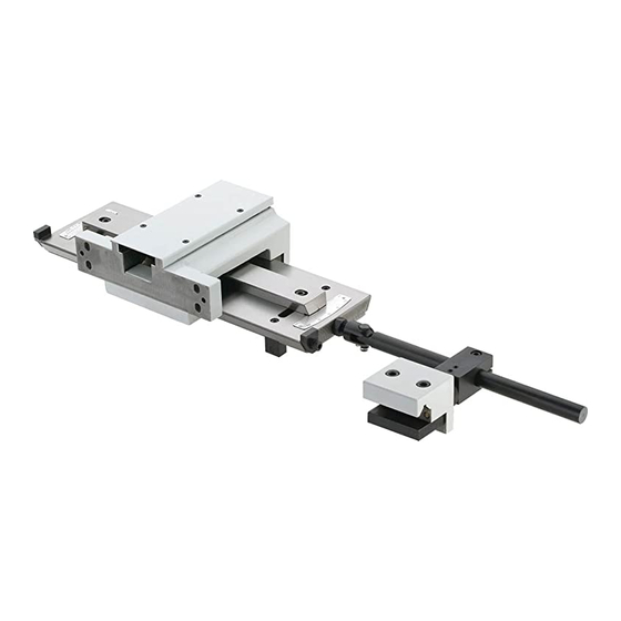
The Model SB1269 taper attachment was
designed to fit onto a series of South Bend
lathes. Shown in Figure 1, is a Model SB1012
lathe that is fitted with the Model SB1269 taper
attachment.
Figure 1. Model SB1269 installed.
This taper attachment mounts quickly to the
⁄
°
1
back bed way of your lathe. Accurate tapers of up
2
to 12" can be produced without repositioning the
⁄
"
1
attachment or having to offset the talstock.
4
The Model SB1269 features scales at both ends,
reading inches-per-foot and degrees. An angle
adjusting knob with fine threads achieves
exacting control when setting tapers.
Another feature is the ability to use the taper
attachment without disengaging the cross slide
nut. This design allows the taper attachment to
be functional at any time by simply tightening
the two deadman-clamp cap screws, which lock
the deadman-clamp to the rear lathe way.
Taper attachment installed
on rear side of lathe
Advertisement
Table of Contents

Related Manuals for South bend SB1269


Summary of Contents for South bend SB1269
-
Page 1: Specifications
Instruction Sheet MODEL SB1269 TAPER ATTACHMENT Introduction The Model SB1269 taper attachment was This taper attachment is heavy! Get designed to fit onto a series of South Bend assistance when installing this accessory on lathes. Shown in Figure 1, is a Model SB1012 the lathe. - Page 2 Model SB1269 I N T R O D U C T I O N For Product Mfg. Since 1/10 Identification Table Main Housing Dovetail Taper Scale Dead Man Clamp Travel Stop Dead Man Adjustment Taper Screws Knob Arm Clevis Figure 2. Identification. Serious personal injury could occur if you Untrained users have an increased risk of connect the lathe to power before completing...
-
Page 3: Things You'll Need
For Product Mfg. Since 1/10 P R E P A R A T I O N Model SB1269 Unpacking Things You'll Need This item was carefully packaged to prevent This attachment is intended to be a permanent damage during transport. If you discover any installation. -
Page 4: Cleaning & Protecting
Model SB1269 P R E P A R A T I O N For Product Mfg. Since 1/10 Cleaning & Protecting The unpainted surfaces are coated with a heavy- Many cleaning solvents are duty rust preventative that prevents corrosion toxic if inhaled. Minimize during shipment and storage. -
Page 5: Installation
For Product Mfg. Since 1/10 P R E P A R A T I O N Model SB1269 Installation Note: Make sure to keep the correct race with its original bearing, and do not hammer on the casting or chisel the inner races out. The To install the taper attachment: inner race has a loose fit. - Page 6 Model SB1269 P R E P A R A T I O N For Product Mfg. Since 1/10 Lift out the slide block without losing the 12. Clean the bearings and races with mineral copper anti-score plug (Figure 8). spirits, then dry and repack them with white lithium grease.
- Page 7 For Product Mfg. Since 1/10 P R E P A R A T I O N Model SB1269 17. Make sure the copper plug is still inside of 21. Apply drops of oil liberally at all four way oil the slide block. ports, both slide block ways, and the pivot pin shown in Figure 14.
- Page 8 Model SB1269 P R E P A R A T I O N For Product Mfg. Since 1/10 Deadman Complete Travel Without Clamp Cap Deadman Clamp Contact Screw Clevis Deadman 1" Saddle Arm Clamp Safety Gap Cap Screw Figure 18. Saddle gap. Figure 16.
- Page 9 For Product Mfg. Since 1/10 P R E P A R A T I O N Model SB1269 35. Loosen the four mounting cap screws and 30. Using a 3mm hex wrench, tighten the rotate the taper attachment left or right to cam set screws and the clevis jam nut (see correct the alignment (see Figure 21).
-
Page 10: Operation
Model SB1269 O P E R A T I O N For Product Mfg. Since 1/10 Operation Using a 6mm hex wrench, loosen the dovetail lock cap screw at each end of the taper attachment, as shown in Figure 24. When the deadman clamp cap screws are loose, the deadman clamp slides along the lathe way, and the taper attachment is disengaged. - Page 11 For Product Mfg. Since 1/10 M A I N T E N A N C E Model SB1269 Using a 6mm hex wrench, loosen both To disable the taper attachment: dovetail lock cap screws (one end shown in Figure 27). DISCONNECT LATHE FROM POWER! Use an 8mm hex wrench, and loosen both Dovetail...
-
Page 12: Maintenance Schedule
Model SB1269 M A I N T E N A N C E For Product Mfg. Since 1/10 Maintenance Schedule Slide Block Ways Slide Block Ways Always disconnect machine from power before performing maintenance or serious personal injury may result. Pivot Pin For optimum performance from your taper attachment, follow this maintenance schedule... - Page 13 For Product Mfg. Since 1/10 P A R T S Model SB1269 Taper Attachment Breakdown -13-...
-
Page 14: Parts List
Model SB1269 P A R T S For Product Mfg. Since 1/10 Parts List REF PART # DESCRIPTION PART # DESCRIPTION PCAP02M CAP SCREW M6-1 X 20 PSB1269028 PSB1269003 BALL OILER PSB1269030 PIVOT SADDLE PSB1269005 END CAP PSB1269031 PFH04M FLAT HD SCR M6-1 X 8 PSB1269032 GIB SCREW PSB1269008... - Page 15 W A R R A N T Y WARRANTY & RETURNS This quality product is warranted by South Bend Lathe Company to the original buyer for one year from the date of purchase. This warranty does not apply to consumable parts, or defects due to any kind of misuse, abuse, negligence, accidents, repairs, alterations or lack of maintenance.
- Page 16 Copyright © February, 2010 By South Bend Lathe Co. Revised April, 2010 (CR). WARNING: No portion of this manual may be reproduced in any shape or form without the written approval of South Bend Lathe Co. #CR12550 Printed in Taiwan. www.southbendlathe.com...
Need help?
Do you have a question about the SB1269 and is the answer not in the manual?
Questions and answers