Table of Contents
Advertisement
Quick Links
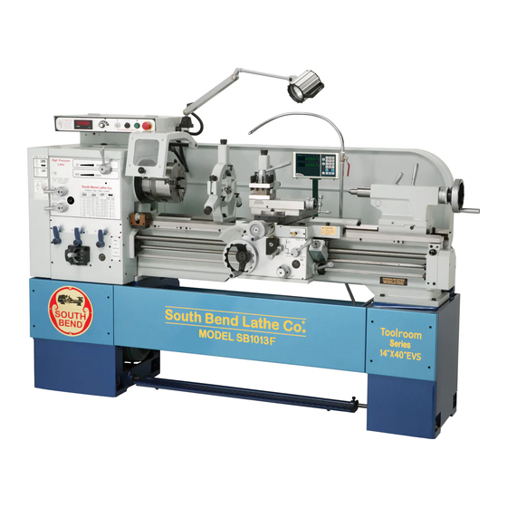
The Model SB1013F Lathe is the same machine as the Model SB1013 except for the following:
•
Addition of 2-Axis Fagor Digital Readout (DRO).
Except for the differences noted in this insert, all other content in the Model SB1013 Owner's Manual
applies to this machine. Before operating your new lathe, you MUST read and understand this insert,
the entire Model SB1013 Owner's Manual, and the Fagor DRO Owner's Manual to reduce the risk of
injury when using this machine. Keep this insert for later reference.
If you have any further questions about this manual insert or the differences between the Model
SB1013F and the Model SB1013, contact our Technical Support at (360) 734-1639 or email
sales@southbendlathe.com.
New & Changed Parts
REF
PART #
2318
PSB1013F2318
2318-1
PSB1013F2318-1
2318-2
PSB1013F2318-2
WARNING: No portion of this manual may be reproduced without written approval.
MODEL SB1013F
14" X 40" LATHE w/DRO
PHONE: (360) 734-1540 •
2318-1
2318-3
2318-2
DESCRIPTION
DRO ASSEMBLY FAGOR 2-AXIS
DRO DISPLAY FAGOR 20-iT
DRO X-AXIS SCALE FAGOR MKT- 154
Copyright © November, 2014 by South Bend Lathe Co.
#MN16947 Printed in USA
Manual Insert
www.southbendlathe.com
2318
REF
PART #
2318-3
PSB1013F2318-3
2407
PSB1013F2407
2416
PSB1013F2416
2407
3 F
0 1
B 1
L S
V S
" E
E
D E
T H
4 0
L A
M O
" x
O M
R O
1 4
e r
m b
R D
R O
N u
O L
a l
S e ri
G O
T O
F A
a te
w /
G D
M F
.1 "
c k
l: 5
m lo
v e
C a
T r a
- 6
n d
D 1
5 "
o u
s e :
6 2
m p
N o
2 .0
C o
# 6
r e :
le
M T
in d
B o
# 4
e r :
S p
M T
n s
le
in d
T a p
ti o
H z
e r :
ic a
S p
6 0
le
T a p
e c if
in d
s .
h ,
S p
c k
7 lb
n d
3 - P
.7 A
S p
9 8
B e
V ,
1 5
s to
T a il
t: 2
u th
2 0
w :
S o
"
H IS
, 2
D r a
"
4 0
ig h
to
.1 7
a n
G T
H P
r s :
"
W e
7 5
T a iw
m p
1 4
S IN
: 5
d :
n te
to r
d A
8 .3
in
E U
B e
C e
d e
e :
.5 "
M o
o a
e r
e e n
S li d
M a
!
H IL
ll L
O v
"
: 6
I N G
Y W
.9 8
F u
tw
s s
x .)
in g
B e
C r o
U R
2 0
M a
c e
R N
IN J
S w
e r
p :
p (
.
ta n
G a
r c e
O v
G a
5 "
W A
A L
D is
o u
e r
9 .2
O N
n d
in g
T o
r s
O v
ir a
S w
s e
e l:
!
R S
w e
in g
P E
g .
N o
r a v
p o
h a
r ti n
S w
e T
U S
n g
le
e d
in d
S li d
s ta
n d
IO
e lo
o l.
S p
S E R
r e
r o u
c u r
s s
ts .
o h
e f o
n .
C r o
O F
a g
; s e
e n
a lc
l b
ti o
te c
o r
g .
IS K
u a
d to
lr y
tm
ju s
g s
r ti n
E R
a n
p r o
w e
a s
c te
a d
d r u
d m
e y e
r je
s ta
d h
T H
n e
o r
s , o
o f
r e
C E
ta n
o n
c e ,
a n
e d
is c
n c e
e f o
D U
e r s
r o v
v e
a n
.
c k
p b
s k in
R E
n d
in e
g lo
te n
lu e
c h u
:
p p
IN E
d u
c e .
g ,
in f
t u
it h
T O
r a
a c h
a in
th e
.
/ s e
t w
th e
C H
a n
e a
p la
th in
th e
e m
, m
te d
ta c
in
M A
a d
s w
ic e
e r
e la
s in
c lo
ju s
ld
R e
a y
e th
n d
c o n
h e
a r d
o s e
e r v
a d
g th
1 .
s u r
r u
A lw
e s
id
r e ly
r ti n
g u
r lo
s .
d o
e r ly
v o
n .
k e
v e
f o r
e c u
2 .
a ll
e a
ti r e
d a
s ta
ti o
M a
le e
b e
r o p
g .
T w
a n
d s
m o
3 .
e p
g s
e r
e n
is p
r e
K e
a n
e f o
n in
N O
w h
r ly
is in
tu r
e .
lo n
o w
in e
n b
4 .
c t p
u la
r ly
c h in
D O
r a te
p e
c k .
n it
r e
u p
a c h
r e g
ti o
d .
m a
5 .
n e
p r o
c h u
u a
r o ll
p e
r o ta
h e
r te
c o n
e m
y o
th e
T o
id
e is
th e
e w
d .
p o
f lu
f u ll
d e
ia l
D is
N O
e th
ie c
s u p
in g
ie c
tt e n
te r
to
6 .
s u r
g h
in
s s
D O
r k p
k e y
r k p
m a
c u tt
o u
n a
r ly
c c e
k e
w o
w o
p e
7 .
th r
c k
g u
th e
d a
M a
g e
p r o
u r e
h u
o r
is e
8 .
a n
c e
n in
f o r
e s
r a n
e c
c k
a r e
C h
r u n
e r v
c h u
r a te
9 .
a k
le a
e th
c e s
s u p
th e
. M
e c
a v
th e
e d
p ie
u n
1 0
s a f
r le
u c h
e la
o r k
p e
r s
v e
e v e
e th
g w
p e
h a
r to
. N
a v
p r o
e v e
lo n
n to
1 1
r le
th e
d r e
. N
e v e
u r e
1 2
e s
s e
c h il
. N
a k
s u
1 3
o w
a y
. M
a ll
1 4
lw
o t
. A
o n
1 5
. D
1 6
2416
DESCRIPTION
DRO Y-AXIS SCALE FAGOR MKT-27
MACHINE ID LABEL
MODEL NUMBER LABEL
Advertisement
Table of Contents

Related Manuals for South bend SB1013F


Summary of Contents for South bend SB1013F
- Page 1 Manual Insert www.southbendlathe.com PHONE: (360) 734-1540 • The Model SB1013F Lathe is the same machine as the Model SB1013 except for the following: • Addition of 2-Axis Fagor Digital Readout (DRO). Except for the differences noted in this insert, all other content in the Model SB1013 Owner’s Manual applies to this machine.
- Page 2 M A N U A L I N S E R T Model SB1013F Mfd. Since 1/12 Model SB1013F 14" x 40" Lathe 440V with Fagor DRO Product Dimensions Weight................................2998 lbs. Width (side-to-side) x Depth (front-to-back) x Height............91-1/2 x 39-1/2 x 59 in.
- Page 3 M A N U A L I N S E R T Mfd. Since 1/12 Model SB1013F Oil Pump Type............................TEFC Induction Horsepower............................1/4 HP Phase..............................3-Phase Amps................................0.6A Speed..............................1725 RPM Power Transfer ..........................Direct Drive Bearings....................Shielded & Permanently Lubricated...
- Page 4 ISO 9001 Factory ..............................No CSA, ETL, or UL Certified/Listed ........................No Features Allen Bradley Electrical Components Fagor 2-Axis DRO Meehanite Casting, Signature South Bend 3 V-Way Bed Safety Chuck Guard with Micro-Switch Shut-Off Halogen Work Light 4-Way Tool Post Complete Recycling Coolant System...
- Page 5 MODELS SB1012/SB1014/SB1037 - 220V MODELS SB1013/SB1015/SB1038 - 440V Compiled Especially for SB1012/SB1013 OWNER'S MANUAL Hundreds of Thousands of Lathes Sold With a Tradition of uality Since 1906! © March, 2010 by South Bend Lathe Co. For Machines Mfg. Since 7/09...
- Page 6 What did you like about it? Is there anything you would change to make it better? Did it meet your expectations for clarity, professionalism, and ease-of-use? South Bend Lathe, Inc. Technical Documentation Manager P.O. Box 2027 Bellingham, WA 98227 Email: manuals@southbendlathe.com...
-
Page 7: Table Of Contents
Table of Contents INTRODUCTION ............3 ..........24 Headstock Controls About These Machines......... 3 ..........24 Carriage Controls ............. 3 ............ 25 Foreword Control Panel ............3 ..........26 Capabilities Tailstock Controls .............. 3 ............26 Features Foot Brake Chuck & Faceplate Mounting ......27 Identification ............ - Page 8 Leadscrew Shear Pin Replacement ....71 ............. 58 Gearbox Gap Removal & Installation ......73 ..............58 Apron ......59 TROUBLESHOOTING .........74 Lead Screw & Feedrod Bearings ............59 Lead Screw WARRANTY & RETURNS ........77 16" South Bend Precision Toolroom Lathe ( Circa 1958...
-
Page 9: Introduction
As the operator and bath oil systems that leave bearings/gears of a South Bend Lathe, you now join the ranks starved for oil when the spindle is first started of some very famous and important customers, and during low speed operations). -
Page 10: Identification
EVS Toolroom Lathes I N T R O D U C T I O N For Machines Mfg. Since 7/09 Identification Figure 1. The 14" & 16" EVS Lathe. A. Headstock O. Leadscrew Bearing Housing B. D1-6 Camlock MT#6 Spindle Cutting Fluid Pump/Tank Control Panel Q. -
Page 11: Safety
S A F E T Y For Machines Mfg. Since 7/09 EVS Toolroom Lathes SAFETY Understanding Risks of Machinery Operating all machinery and machining equipment can be dangerous or relatively safe depending on how it is installed and maintained, and the operator's experience, common sense, risk awareness, working conditions, and use of personal protective equipment (safety glasses, respirators, etc.). - Page 12 EVS Toolroom Lathes S A F E T Y For Machines Mfg. Since 7/09 Entanglement: Loose clothing, gloves, 11. Chuck Keys or Adjusting Tools: Tools used neckties, jewelry or long hair may to adjust spindles, chucks, or any moving/ get caught in moving parts, causing rotating parts will become dangerous entanglement, amputation, crushing, projectiles if left in place when the machine...
-
Page 13: Additional Metal Lathe Safety
S A F E T Y For Machines Mfg. Since 7/09 EVS Toolroom Lathes Additional Metal Lathe Safety Clearing Chips. Metal chips can easily cut Speed Rates. Operating the lathe at the bare skin—even through a piece of cloth. wrong speed can cause nearby parts to break Avoid clearing chips by hand or with a rag. -
Page 14: Preparation
EVS Toolroom Lathes P R E P A R A T I O N For Machines Mfg. Since 7/09 PREPARATION Preparation Overview Things You'll Need The purpose of the preparation section is to help To complete the preparation process, you will you prepare your machine for operation. -
Page 15: Inventory
P R E P A R A T I O N For Machines Mfg. Since 7/09 EVS Toolroom Lathes Inventory Main Inventory 1: (Figure A. Steady Rest Assembly ........1 B. 12" Faceplate w/D1-6 Camlock Stud Set ..1 10" Four-Jaw Chuck w/Combo Jaws ..... 1 D. -
Page 16: Cleaning & Protecting
EVS Toolroom Lathes P R E P A R A T I O N For Machines Mfg. Since 7/09 Cleaning & Protecting The unpainted surfaces are coated at the factory Many cleaning solvents are with a heavy-duty rust preventative that toxic if inhaled. -
Page 17: Location
P R E P A R A T I O N For Machines Mfg. Since 7/09 EVS Toolroom Lathes Weight Load Location Refer to the Machine Specifications for the weight of your machine. Make sure that the Physical Environment surface upon which the machine is placed will The physical environment where your machine Physical Environment bear the weight of the machine, additional... -
Page 18: Lifting & Moving
EVS Toolroom Lathes P R E P A R A T I O N For Machines Mfg. Since 7/09 To further balance the load, loosen the Lifting & Moving carriage lock bolt (see Figure 6), disengage the half nut lever, put the feed control lever in neutral, then use the carriage handwheel to move the carriage next to the tailstock. -
Page 19: Leveling & Mounting
P R E P A R A T I O N For Machines Mfg. Since 7/09 EVS Toolroom Lathes Attach the lifting straps to forklift forks or a Leveling & Mounting hook and chain, as shown in Figures 8–9. You must level your machine and either use the included foot pads and leveling hardware or bolt Forklift your lathe to the floor. -
Page 20: Bolting To Concrete Floors
EVS Toolroom Lathes P R E P A R A T I O N For Machines Mfg. Since 7/09 To level the machine, use a precision level to Assembly make sure the bedways are level from side-to- side and from front-to-back. With the exception of the handwheel handles, the lathe is shipped fully assembled. -
Page 21: Adding Cutting Fluid
P R E P A R A T I O N For Machines Mfg. Since 7/09 EVS Toolroom Lathes In addition to the gearboxes, we also recommend that you lubricate all other points on the machine at this time. This can be accomplished This machine is equipped with a frequency by following the maintenance schedule on Page drive that contains sensitive electronics,... -
Page 22: Connecting Power Cord To Lathe
EVS Toolroom Lathes P R E P A R A T I O N For Machines Mfg. Since 7/09 Connecting Power Cord to Lathe To Power Source G G G G Electrocution or death will occur if you attempt this procedure with the power cord Ground connected to the power source. -
Page 23: Correcting Out-Of-Phase Wiring
P R E P A R A T I O N For Machines Mfg. Since 7/09 EVS Toolroom Lathes Test Run Locking Disconnect Switch Power Source Machine After all preparation steps have been completed, the machine and its safety features must be tested to ensure correct operation. - Page 24 EVS Toolroom Lathes P R E P A R A T I O N For Machines Mfg. Since 7/09 Move the feed direction forward/reverse lever to the middle (neutral) position, as shown in Stop Button Figure 20. Pump Switch ORWARD EUTRAL EVERSE Figure 17.
- Page 25 P R E P A R A T I O N For Machines Mfg. Since 7/09 EVS Toolroom Lathes 11. Move the spindle ON/OFF lever to the OFF Note: This headstock has a pressurized oil (center) position, as shown in Figure 22. system that is equipped with an oil pressure safety switch.
- Page 26 EVS Toolroom Lathes P R E P A R A T I O N For Machines Mfg. Since 7/09 18. Move the spindle ON/OFF lever up to the 22. Replace the headstock side cover, then start OFF position, reset the stop button by the lathe again.
-
Page 27: Spindle Break-In
P R E P A R A T I O N For Machines Mfg. Since 7/09 EVS Toolroom Lathes Move the feed direction forward/reverse lever Spindle Break-In (Figure 28) to the neutral position. It is essential to closely follow the proper break-in ORWARD procedures to ensure trouble-free performance. -
Page 28: Recommended Adjustments
EVS Toolroom Lathes P R E P A R A T I O N For Machines Mfg. Since 7/09 Disengage the half nut and the feed control After completing the previous step, stop the levers shown in Figures 30–31. spindle and move the gearbox range lever to neutral, then move the spindle speed range lever to high. -
Page 29: Operation
For Machines Mfg. Since 7/09 O P E R A T I O N EVS Toolroom Lathes OPERATION To complete a typical operation, the operator Operation Overview does the following: The purpose of this overview is to provide Puts on safety glasses, rolls up sleeves, the novice machine operator with a basic removes jewelry, and secures any clothing, understanding of how the machine is used during... -
Page 30: Description Of Controls & Components
EVS Toolroom Lathes O P E R A T I O N For Machines Mfg. Since 7/09 A. Change Gear Chart: Displays the positions of Description of Controls the various gears for different threading or turning options. & Components B. Spindle Speed Range Lever: Shifts the Refer to the following figures and descriptions headstock into low or high range for spindle to become familiar with the basic controls of this... -
Page 31: Control Panel
For Machines Mfg. Since 7/09 O P E R A T I O N EVS Toolroom Lathes H. Cutting Fluid Flow Control Lever: Controls Control Panel the flow of cutting fluid from the nozzle. Compound Slide Handwheel: Moves the compound slide forward or backward. Includes an indirect-read graduated scale (distance represents actual tool movement—... -
Page 32: Tailstock Controls
EVS Toolroom Lathes O P E R A T I O N For Machines Mfg. Since 7/09 Tailstock Controls Foot Brake This lathe is equipped with a foot brake (Figure 38) to quickly stop the spindle. Pushing the foot brake while the spindle is ON cuts power to the motor and stops the spindle. -
Page 33: Chuck & Faceplate Mounting
For Machines Mfg. Since 7/09 O P E R A T I O N EVS Toolroom Lathes One at a time, use the chuck key to turn Chuck & Faceplate each of the camlocks counterclockwise until the cam line aligns with the cam release Mounting datum line, as shown in Figure 40. -
Page 34: Mounting Chuck Or Faceplate
EVS Toolroom Lathes O P E R A T I O N For Machines Mfg. Since 7/09 Tighten camlocks in a star pattern to draw Mounting Chuck or Faceplate the chuck up evenly on all sides while The 4-jaw chuck is shipped with six camlock reducing chance of alignment, and make studs that must be installed before the chuck sure to tighten camlocks in an incremental... -
Page 35: Installing And Adjusting Camlock Studs
For Machines Mfg. Since 7/09 O P E R A T I O N EVS Toolroom Lathes Installing and Adjusting Camlock Studs Camlock Stud Depth Chuck/Faceplate Mark is Even with Chuck When fitting a chuck or faceplate with camlock or Faceplate Surface studs, or when mounting a new chuck or faceplate, it may be necessary to install or adjust the camlock studs. -
Page 36: 3-Jaw Chuck
EVS Toolroom Lathes O P E R A T I O N For Machines Mfg. Since 7/09 Not Correct Correct Not Correct Figure 48. Correct camlock stud alignment. 3-Jaw Chuck Numbered from 1–3, the jaws must be used in Refer to Chuck & Faceplate Mounting the matching numbered jaw guides, as shown in instructions on Page 27 to mount the 3-jaw Figure 50. -
Page 37: Changing Jaws
For Machines Mfg. Since 7/09 O P E R A T I O N EVS Toolroom Lathes — If installed correctly, the jaws converge Changing Jaws together at the center of the chuck. Item Needed Chuck Key ............. 1 — If the jaws do not come together, remove White Lithium Grease ...... -
Page 38: 4-Jaw Chuck
EVS Toolroom Lathes O P E R A T I O N For Machines Mfg. Since 7/09 After the workpiece is held in place by 4-Jaw Chuck the jaws, turn the chuck by hand and pay attention to the workpiece alignment. Refer to Chuck &... -
Page 39: Moving Along Bedway
For Machines Mfg. Since 7/09 O P E R A T I O N EVS Toolroom Lathes To install tooling in the tailstock: Moving Along Bedway With the tailstock locked in place, unlock the Pull the tailstock lock lever backward (away quill, then use the handwheel to extend it to from the spindle) to unlock the tailstock from the 1"... -
Page 40: Offsetting
EVS Toolroom Lathes O P E R A T I O N For Machines Mfg. Since 7/09 Offsetting Aligning The tailstock can be offset from the spindle The offset of your lathe was aligned with center line for turning tapers. The offset the spindle center line at the factory. - Page 41 For Machines Mfg. Since 7/09 O P E R A T I O N EVS Toolroom Lathes Note: As long as this dead center remains in the Use a caliper to measure both ends of the chuck, the point of the center will remain workpiece.
-
Page 42: Faceplate
EVS Toolroom Lathes O P E R A T I O N For Machines Mfg. Since 7/09 Faceplate Non-Cylindrical Workpiece Refer to Chuck & Faceplate Mounting instructions on Page 27 to mount the faceplate to the spindle. The 12" faceplate included with your lathe offers a wide range of uses, including machining non- concentric workpieces, straight turning between centers, off-center turning, and boring. -
Page 43: Centers
For Machines Mfg. Since 7/09 O P E R A T I O N EVS Toolroom Lathes Mounting Dead Center in Spindle Centers DISCONNECT LATHE FROM POWER! Figure 65 shows the dead centers included with the lathe. In addition, an MT#6–MT#4 tapered Thoroughly clean and dry the tapered spindle sleeve is included for mounting centers in mating surfaces of the spindle bore, tapered... -
Page 44: Removing Center From Spindle
EVS Toolroom Lathes O P E R A T I O N For Machines Mfg. Since 7/09 To mount a center in the tailstock: Removing Center from Spindle DISCONNECT LATHE FROM POWER! To remove the sleeve and center from the spindle, insert a piece of round bar stock or Thoroughly clean and dry the tapered similar tool through the outboard end (on the left... -
Page 45: Steady Rest
For Machines Mfg. Since 7/09 O P E R A T I O N EVS Toolroom Lathes Close the steady rest so that the workpiece Steady Rest is inside the finger rollers, then tighten the lock knob. The steady rest supports long shafts and can be mounted anywhere along the length of the bed. -
Page 46: Compound Slide
EVS Toolroom Lathes O P E R A T I O N For Machines Mfg. Since 7/09 Compound Slide Four-Way Tool Post The compound slide handwheel has an indirect- The four-way tool post is mounted on top of the read graduated scale. This means that the compound slide and allows a maximum of four distance shown on the scale represents the tools to be loaded simultaneously. -
Page 47: Aligning Cutting Tool With Tailstock Center
For Machines Mfg. Since 7/09 O P E R A T I O N EVS Toolroom Lathes Tools Needed Aligning Cutting Tool with Tool Post T-Wrench ..........1 Tailstock Center Steel Shim ..........As Needed For most operations, the cutting tool tip should Cutting Tool ............ -
Page 48: Adjustable Apron Stop System
EVS Toolroom Lathes O P E R A T I O N For Machines Mfg. Since 7/09 Adjustable Apron Stop Carriage Stop System Use the adjustable apron stop collar (shown in The carriage stop on this lathe will NOT Figure 75) to set the location where the carriage automatically stop the carriage or disengage will be disengaged by the feedrod friction clutch. -
Page 49: Manual Feed
For Machines Mfg. Since 7/09 O P E R A T I O N EVS Toolroom Lathes Manual Feed Spindle Speed You can manually move the cutting tool around Using the correct spindle speed is important the lathe for facing or turning operations using for safe and satisfactory results, as well as the handwheels shown in Figure 77 and maximizing tool life. -
Page 50: Setting Spindle Speed
EVS Toolroom Lathes O P E R A T I O N For Machines Mfg. Since 7/09 Setting Spindle Speed Make sure the spindle is turned OFF and it Make sure the variable speed dial is turned all has come to a complete stop. the way to the left (counterclockwise) before turning the lathe ON, or it may start up at a Use the chart in Figure 79 to determine the... -
Page 51: Power Feed Controls
For Machines Mfg. Since 7/09 O P E R A T I O N EVS Toolroom Lathes Use the feed control lever on the front of the Power Feed Controls apron to engage power feed for either the The feed direction lever (Figure 81) controls carriage or the cross slide (see Figure 83). -
Page 52: Understanding Thread & Feed Rate Chart
EVS Toolroom Lathes O P E R A T I O N For Machines Mfg. Since 7/09 Understanding Thread & Feed Rate Chart Figure 84 shows the configurations of gearbox levers that are required to set the available feed rates. This same chart can also be found on the machine. -
Page 53: End Gear Setup
For Machines Mfg. Since 7/09 O P E R A T I O N EVS Toolroom Lathes End Gear Setup Alternate Position The gearbox drive gear on this lathe can be When the 44- and 57-tooth end gears are meshed configured for the "normal position"... -
Page 54: Threading Controls
EVS Toolroom Lathes O P E R A T I O N For Machines Mfg. Since 7/09 Note: Take care not to misplace the key from the gear shaft. Disengaged Cross Slide Neutral Clean away debris and grime from the Carriage gear and apply a light coat of machine oil. -
Page 55: Using Thread Dial And Chart
For Machines Mfg. Since 7/09 O P E R A T I O N EVS Toolroom Lathes TPI 2-54 Not Divisible By 4 Using Thread Dial and Chart Use any of the non-numbered lines on the thread Find the TPI (threads per inch) that you want dial for threading the TPI shown in Figure 94. -
Page 56: Chip Drawer
EVS Toolroom Lathes O P E R A T I O N For Machines Mfg. Since 7/09 Other Fractional TPI Chip Drawer Use position 1 on the thread dial for cutting the The chip drawer shown in Figure 99 catches TPI shown in Figure 97. -
Page 57: Cutting Fluid System
For Machines Mfg. Since 7/09 O P E R A T I O N EVS Toolroom Lathes Cutting Fluid System The cutting fluid system delivers cutting fluid BIOLOGICAL & POISON through a positionable nozzle and is turned ON/ HAZARD! OFF by the control panel cutting fluid pump Use the correct personal switch and the valve lever near the base of the protection equipment... -
Page 58: Accessories
This section includes the most common promising quality. accessories available for your lathe, which may be available through your local South Bend Lathe Co. dealer. If you do not have a dealer in heat treated to HRC60 ± 1 for high rigidity your area, please call us at (360) 734-1540 or and durability. - Page 59 0.67" 2.48" SB1300 0.47" 60° Figure 106. Antique-finished South Bend shop clocks. SBL Gearhead T-Shirt SBL One Good Turn T-Shirt Figure 104. SB1247 MT4 Bull Nose Center. 100% Cotton, preshrunk T-shirts, available in sizes S, M, L, XL, 2XL, 3XL.
-
Page 60: Maintenance
EVS Toolroom Lathes M A I N T E N A N C E For Machines Mfg. Since 7/09 MAINTENANCE Maintenance Schedule Daily, During Operations turned ON (Page 56). Always disconnect power 170° F. to the machine before performing maintenance. Daily, After Operations Failure to do this may result in electrocution or... -
Page 61: Maintenance Chart
M A I N T E N A N C E For Machines Mfg. Since 7/09 EVS Toolroom Lathes Maintenance Chart -55-... -
Page 62: Lubrication
EVS Toolroom Lathes M A I N T E N A N C E For Machines Mfg. Since 7/09 Monitoring Oil Temperature Lubrication During operations, regularly monitor the oil temperature shown in the sight glass in Figure Headstock 109. The temperature of the headstock oil must Oil Type .. - Page 63 M A I N T E N A N C E For Machines Mfg. Since 7/09 EVS Toolroom Lathes After the tank is completely cleaned out, Cleaning Pump System & Changing Oil unthread the screen from the bottom of the The headstock oil pump system must be cleaned pump suction pipe (see Figure 111), and and the oil changed after the break-in period and...
-
Page 64: Gearbox
EVS Toolroom Lathes M A I N T E N A N C E For Machines Mfg. Since 7/09 Gearbox Apron Oil Type ..Mobil Vactra 2 or ISO 68 Equivalent Oil Type ..Mobil Vactra 2 or ISO 68 Equivalent Oil Amount ...........1 Liter Oil Amount ...........1 Liter Check/Add Frequency ........ -
Page 65: Lead Screw & Feedrod Bearings
M A I N T E N A N C E For Machines Mfg. Since 7/09 EVS Toolroom Lathes Lead Screw & Feedrod Bearings Ways & Slides Oil Type ..Mobil Vactra 2 or ISO 68 Equivalent The way pump shown in Figure 117 lubricates Oil Amount ...........1 Liter the saddle and cross slide way guides with the oil Check/Add Frequency ........ -
Page 66: Ball Oilers
EVS Toolroom Lathes M A I N T E N A N C E For Machines Mfg. Since 7/09 Ball Oilers Cleaning Electrical Box Filter Oil Type .. Mobil DTE Light or ISO 32 Equivalent The door of the electrical box contains an air Oil Amount ..........1 or 2 Drops filter (Figure 120) to prevent dust from entering Lubrication Frequency ........ -
Page 67: End Gearing
M A I N T E N A N C E For Machines Mfg. Since 7/09 EVS Toolroom Lathes End Gearing Lubricating DISCONNECT LATHE FROM POWER! Grease Type ..........NLGI#2 Frequency ....Annually or When Swapping Remove the headstock side cover and all the end gears shown in Figure 121. -
Page 68: Cutting Fluid System
EVS Toolroom Lathes M A I N T E N A N C E For Machines Mfg. Since 7/09 Hazards Cutting Fluid System As some cutting fluid ages, dangerous microbes The cutting fluid system consists of a fluid tank, can proliferate and create a biological hazard. pump, and flexible nozzle. -
Page 69: Changing Cutting Fluid
M A I N T E N A N C E For Machines Mfg. Since 7/09 EVS Toolroom Lathes Note: The electrical conduit was purposely left Changing Cutting Fluid long, so the tank can be removed without When you replace the old cutting fluid, take the disconnecting wires from the pump. -
Page 70: Machine Storage
EVS Toolroom Lathes M A I N T E N A N C E For Machines Mfg. Since 7/09 To prepare your machine for long-term storage (a Machine Storage year or more): If the machine is not properly prepared for Run the lathe for 10 minutes to bring the storage, it may develop rust or corrosion. -
Page 71: Service
S E R V I C E For Machines Mfg. Since 7/09 EVS Toolroom Lathes SERVICE Cross Slide Leadscrew Backlash Adjustment Tools Needed: Backlash is the amount of free play felt Hex Wrench 3mm ..........1 while switching rotation directions with Hex Wrench 5mm .......... -
Page 72: Leadscrew End Play Adjustment
EVS Toolroom Lathes S E R V I C E For Machines Mfg. Since 7/09 Leadscrew End Play Gib Adjustment The goal of adjusting the cross slide, tailstock, Adjustment saddle, and compound gib screws is to remove sloppiness in the ways without over-adjusting After a long period of time, you may find that the them to the point where the slides become stiff leadscrew develops a small amount of end play. -
Page 73: Half Nut Adjustment
S E R V I C E For Machines Mfg. Since 7/09 EVS Toolroom Lathes Half Nut Adjustment The half nut mechanism can be tightened if it becomes loose from wear. The pressure exerted by the half nut is controlled by a gib similar to the one in the saddle, which is on Page 66. -
Page 74: Feedrod Clutch Adjustment
EVS Toolroom Lathes S E R V I C E For Machines Mfg. Since 7/09 Insert the hex wrench into the collar Feedrod Clutch adjustment hole shown in Figure 135, and use the wrench to rotate the clutch collar. Adjustment —... -
Page 75: V-Belts
S E R V I C E For Machines Mfg. Since 7/09 EVS Toolroom Lathes V-Belts Brake & Switch V-belts stretch and wear with use, so check them As the brake lining wears, the foot pedal on a monthly basis to ensure optimal power develops more travel. - Page 76 EVS Toolroom Lathes S E R V I C E For Machines Mfg. Since 7/09 Remove pedal stop shown in Figure 139. Move the brake band to the right one hole, Pedal Stop and re-install the pedal stop, tightening it until it is just snug.
-
Page 77: Leadscrew Shear Pin Replacement
S E R V I C E For Machines Mfg. Since 7/09 EVS Toolroom Lathes Rotate the shroud washer so the cutout lines Leadscrew Shear Pin up with the shear pin head, as shown in Figure 144. Replacement Shroud Washer Shear Pin Head 0.5mm... - Page 78 EVS Toolroom Lathes S E R V I C E For Machines Mfg. Since 7/09 Use the magnet to remove the shear pin Instead, take the time to carefully line head, then rotate the lathe spindle to line up the two bores. You may file a slight up the inner and outer bores, as shown in chamfer on the end of the pin to make it Figure 146.
-
Page 79: Gap Removal & Installation
S E R V I C E For Machines Mfg. Since 7/09 EVS Toolroom Lathes Remove the two way end cap screws and way Gap Removal & set screws shown in Figure 151. Installation Tighten the two dowel pin jack nuts (Figure 151) until the pins are pulled free from the A portion of the lathe bed directly under the gap insert. -
Page 80: Troubleshooting
EVS Toolroom Lathes TROU B LESHOOTI NG For Machines Mfg. Since 7/09 TROUBLESHOOTING If you need replacement parts, or if you are unsure how to do any of the solutions given here, feel free to call us at (360) 734-1540. Symptom Possible Cause Possible Solution... - Page 81 TROU B LESHOOTI NG For Machines Mfg. Since 7/09 EVS Toolroom Lathes Symptom Possible Cause Possible Solution Entire machine 1. Workpiece is unbalanced. 1. Re-install workpiece as centered with the spindle bore as possible. vibrates upon startup and while 2. Loose or damaged belt(s). 2.
- Page 82 EVS Toolroom Lathes TROU B LESHOOTI NG For Machines Mfg. Since 7/09 Symptom Possible Cause Possible Solution Workpiece is 1. Headstock and tailstock are not 1. Realign the tailstock to the headstock spindle bore properly aligned with each other. centerline (Page 34). tapered.
-
Page 83: Warranty & Returns
WARRANTY & RETURNS Warranty This quality product is warranted by South Bend Lathe Company to the original buyer for one year from the date of purchase. This warranty does not apply to consumable parts, or defects due to any kind of misuse, abuse, negligence, accidents, repairs, alterations or lack of maintenance. We do not reimburse for third party repairs. - Page 84 South Bend Lathe Co. P.O. Box 2027 Bellingham, WA 98227 PHONE: (360) 734-1540 (Administrative Offi ces) FAX: (360) 676-1075 (International) FAX: (360) 734-1639 (USA only) southbendlathe.com Printed In Taiwan #BLTRCR12117...
- Page 85 14" X 40" EVS TOOLROOM LATHES MODEL SB1012 - 220V MODEL SB1013 - 440V SPECIFICATIONS Hundreds of Thousands of Lathes Sold With a Tradition of uality Since 1906! © March, 2010 by South Bend Lathe Co. For Machines Mfg. Since 7/09...
- Page 86 Machine Specifications P.O. Box 2027, Bellingham, WA 98227 U.S.A. © South Bend Lathe Co. www.southbendlathe.com Model SB1012 14" x 40" EVS Toolroom Lathe Product Dimensions: Weight ..................................2970 lbs. Length/Width/Height ..........................91 ⁄ " x 39 ⁄ " x 59" Foot Print (Length/Width) ............................82" x 19 ⁄...
- Page 87 Coolant Type ...............................TEFC Induction Horsepower ................................⁄ Voltage ..................................220V Phase .................................. 3-Phase Amps ..................................0.3A Speed ................................3450 RPM Cycle ..................................60 Hz Number of Speeds ................................1 Power Transfer ............................Direct Drive Bearings ........................Shielded and Permanently Sealed Main Specifications: Operation Information Swing Over Bed ..............................
- Page 88 Serial Number Location ....................ID Label on Rear Side of Left Stand Customer Setup and Cleaning Time ....................Approximately 2 Hours Features: Allen Bradley Electrical Components Meehanite Casting, Signature South Bend 3 V-Way Bed Safety Chuck Guard with Micro-Switch Shut-Off Halogen Work Light 4-Way Tool Post...
- Page 89 Machine Specifications P.O. Box 2027, Bellingham, WA 98227 U.S.A. www.southbendlathe.com Model SB1013 14" x 40" EVS Toolroom Lathe Product Dimensions: Weight ..................................2970 lbs. Length/Width/Height ..........................91 ⁄ " x 39 ⁄ " x 59" Foot Print (Length/Width) ............................82" x 19 ⁄...
- Page 90 Coolant Type ...............................TEFC Induction Horsepower ................................⁄ Voltage ..................................440V Phase .................................. 3-Phase Amps ..................................0.15A Speed ................................3450 RPM Cycle ..................................60 Hz Number of Speeds ................................1 Power Transfer ............................Direct Drive Bearings ........................Shielded and Permanently Sealed Main Specifications: Operation Information Swing Over Bed ..............................
- Page 91 Serial Number Location ....................ID Label on Rear Side of Left Stand Customer Setup and Cleaning Time ....................Approximately 2 Hours Features: Allen Bradley Electrical Components Meehanite Casting, Signature South Bend 3 V-Way Bed Safety Chuck Guard with Micro-Switch Shut-Off Halogen Work Light 4-Way Tool Post...
- Page 92 South Bend Lathe Co. P.O. Box 2027 Bellingham, WA 98227 PHONE: (360) 734-1540 (Administrative Offi ces) FAX: (360) 676-1075 (International) FAX: (360) 734-1639 (USA only) southbendlathe.com Printed In Taiwan #BL12115-12161...
- Page 93 14" & 16" EVS TOOLROOM LATHES MODELS SB1012/SB1014/SB1037 - 220V MODELS SB1013/SB1015/SB1038 - 440V WIRING MANUAL Hundreds of Thousands of Lathes Sold With a Tradition of uality Since 1906! © November, 2009 by South Bend Lathe Co. For Machines Mfg. Since 7/09...
- Page 94 What did you like about it? Is there anything you would change to make it better? Did it meet your expectations for clarity, professionalism, and ease-of-use? South Bend Lathe, Inc. Technical Documentation Manager P.O. Box 2027 Bellingham, WA 98227 Email: manuals@southbendlathe.com...
- Page 95 For Machines Mfg. Since 8/09 EVS Toolroom Lathes E L E C T R I C A L ELECTRICAL Electrical Safety Instructions These pages are accurate at the time of printing. In the constant effort to improve, however, we may make changes to the electrical systems of future machines.
- Page 96 EVS Toolroom Lathes For Machines Mfg. Since 8/09 E L E C T R I C A L wiring overview Wiring Overview Power Supply Electrical Connection Box, Pages 6 Page 13. & 7. 220 VAC 3-PH Spindle RPM Work Lamp, Sensor, Page 14.
- Page 97 For Machines Mfg. Since 8/09 EVS Toolroom Lathes E L E C T R I C A L visual index Component Location Index Cooling Fan, Work Lamp, Page 6. Page 14. Electrical Box, Pages 6 & 7. Main Power Coolant Switch, Page 6.
- Page 98 EVS Toolroom Lathes For Machines Mfg. Since 8/09 E L E C T R I C A L box1 Electrical Box Wiring FOR SB1012/SB1014/SB1037 220V: RANGE 1.6A–2.4A, SET AT 1.8A FOR SB1013/SB1015/SB1038 440V: RANGE 0.6A–1.0A, SET AT 0.8A FOR 220V: RANGE 0.24A–0.4A, SET AT 0.35A FOR 440V: RANGE 0.24A–0.4A, SET AT 0.24A...
- Page 99 For Machines Mfg. Since 8/09 EVS Toolroom Lathes E L E C T R I C A L box2 Electrical Box Wiring...
- Page 100 EVS Toolroom Lathes For Machines Mfg. Since 8/09 E L E C T R I C A L box photo Electrical Box Fig. 2. Electrical box.
- Page 101 For Machines Mfg. Since 8/09 EVS Toolroom Lathes E L E C T R I C A L 220V Spindle Motor Junction Box Ground SPINDLE MOTOR (220V) Figure. 3. Spindle motor location. To Electrical Box, Page 7. 440V Spindle Motor Junction Box Ground SPINDLE...
- Page 102 EVS Toolroom Lathes For Machines Mfg. Since 8/09 E L E C T R I C A L 220V Oil Pump Motor & Pressure Sensor To Electrical PRESSURE Box, Page 7. X 11 Oil Pressure SENSOR Sensor and Pump Oil Pump U2 V2 Motor Ground...
- Page 103 For Machines Mfg. Since 8/09 EVS Toolroom Lathes E L E C T R I C A L 220V Coolant Pump Wiring To Electrical Box, Page 7. Coolant Pump 5 W1 Figure. 7. Coolant pump location. Ground Ground COOLANT PUMP MOTOR (220V) 440V Coolant Pump Wiring To Electrical...
- Page 104 EVS Toolroom Lathes For Machines Mfg. Since 8/09 E L E C T R I C A L Control Panel Wiring control panel and coolant mo- Control Panel Fig. 9. Control panel location. To Electrical Box, Page 7. To Main Junction To Main Junction To Circuit To Circuit...
- Page 105 For Machines Mfg. Since 8/09 EVS Toolroom Lathes E L E C T R I C A L spindle rotation Spindle Rotation Switch and power conn- tection To Main Junction Spindle Rotation Block, Page 7. Switch Spindle Rotation Switch, Figure 10. Fig.
- Page 106 EVS Toolroom Lathes For Machines Mfg. Since 8/09 E L E C T R I C A L Additional Component Wiring Spindle RPM Sensor Door Limit Work Light Switch additional com- pontnet Fig. 11. RPM sensor and door limit switch location. Door Limit Switch, Figure 11.
- Page 107 WARRANTY & RETURNS Warranty This quality product is warranted by South Bend Lathe Company to the original buyer for one year from the date of purchase. This warranty does not apply to consumable parts, or defects due to any kind of misuse, abuse, negligence, accidents, repairs, alterations or lack of maintenance. We do not reimburse for third party repairs.
- Page 108 South Bend Lathe Co. P.O. Box 2027 Bellingham, WA 98227 PHONE: (360) 734-1540 (Administrative Offi ces) FAX: (360) 676-1075 (International) FAX: (360) 734-1639 (USA only) southbendlathe.com Printed In Taiwan #JB12236...
- Page 109 MODEL SB1012 - 220V MODEL SB1013 - 440V PARTS MANUAL Hundreds of Thousands of Lathes Sold With a Tradition of uality Since 1906! © November, 2009 by South Bend Lathe Co., Revised February, 2010 (TS) For Machines Mfg. Since 7/09...
- Page 110 What did you like about it? Is there anything you would change to make it better? Did it meet your expectations for clarity, professionalism, and ease-of-use? South Bend Lathe, Inc. Technical Documentation Manager P.O. Box 2027 Bellingham, WA 98227 Email: manuals@southbendlathe.com...
- Page 111 Table of Contents Headstock Casing ............................2 Headstock Controls ............................3 Headstock Upper Gearing .........................5 Headstock Transfer Gearing ........................7 Gearbox Gearing ............................8 Gearbox Controls .............................10 Apron - Front View ..........................12 Apron - Rear View ............................14 Dial Indicator ............................16 Carriage Stop ............................16 Compound Slide & Tool Post ........................17 Saddle Body &...
-
Page 112: Headstock Casing
Model SB1012/SB1013 Parts For Machines Mfg. Since 8/09 P A R T S Headstock Casing PART # DESCRIPTION PART # DESCRIPTION PSB10120001 OIL FILL PLUG PFH30M FLAT HD SCR M5-.8 X 8 PCAP29M CAP SCREW M6-1 X 40 PSB10120009 OIL DISTRIBUTOR A-5S PSB10120003 HEADSTOCK COVER PSB10120009-1 OIL DISTRIBUTOR BRACKET... -
Page 113: Headstock Controls
For Machines Mfg. Since 8/09 Model SB1012/SB1013 Parts P A R T S Headstock Controls 45 44... - Page 114 Model SB1012/SB1013 Parts For Machines Mfg. Since 8/09 P A R T S Headstock Controls Parts List PART # DESCRIPTION PART # DESCRIPTION PSS30M SET SCREW M10-1.5 X 10 PSB10120033 HANDLE WASHER 6MM PSB10120015 THREADED PLUG M10-1.5 PCAP01M CAP SCREW M6-1 X 16 PSB10120016 COMPRESSION SPRING M8 X 37 PSB10120035...
-
Page 115: Headstock Upper Gearing
For Machines Mfg. Since 8/09 Model SB1012/SB1013 Parts P A R T S Headstock Upper Gearing... - Page 116 Model SB1012/SB1013 Parts For Machines Mfg. Since 8/09 P A R T S Headstock Upper Gearing Parts List PART # DESCRIPTION PART # DESCRIPTION PCAP01M CAP SCREW M6-1 X 16 PSB10120078 SPINDLE PULLEY PSB10120055 INBOARD DRIVE SHAFT END CAP PSB10120079 PULLEY WASHER 8MM PORG050 O-RING 54.4 X 3.1 G50...
-
Page 117: Headstock Transfer Gearing
For Machines Mfg. Since 8/09 Model SB1012/SB1013 Parts P A R T S Headstock Transfer Gearing PART # DESCRIPTION PART # DESCRIPTION PCAP01M CAP SCREW M6-1 X 16 PSB10120116 GEAR SHAFT PR15M EXT RETAINING RING 30MM PR09M EXT RETAINING RING 20MM PSB10120105 GEAR FENDER WASHER 6MM PSB10120118... -
Page 118: Gearbox Gearing
Model SB1012/SB1013 Parts For Machines Mfg. Since 8/09 P A R T S Gearbox Gearing... - Page 119 For Machines Mfg. Since 8/09 Model SB1012/SB1013 Parts P A R T S Gearbox Gearing Parts List PART # DESCRIPTION PART # DESCRIPTION PSB10120201 SPLINE SHAFT PSB10120232 GEAR 19T PSB10120202 OIL SEAL 20 X 32 X 5 PSB10120233 GEAR 20T PSB10120203 SLEEVE BEARING TAF202820 PSB10120234...
-
Page 121: Gearbox Controls
For Machines Mfg. Since 8/09 Model SB1012/SB1013 Parts P A R T S Gearbox Controls Parts List PART # DESCRIPTION PART # DESCRIPTION PSB10120262 GEARBOX COVER GASKET PSB10120289 WOODRUFF KEY 4 X 13 PSB10120263 PARTITION NUT PSB10120302 SHIFT SHAFT PSB10120264 UPPER PLATE PORP018 O-RING 17.8 X 2.4 P18... -
Page 122: Apron - Front View
Model SB1012/SB1013 Parts For Machines Mfg. Since 8/09 P A R T S Apron - Front View -12-... - Page 123 For Machines Mfg. Since 8/09 Model SB1012/SB1013 Parts P A R T S Apron - Front View Parts List PART # DESCRIPTION PART # DESCRIPTION PSB10120501 DOUBLE GEAR 18T/60T PORP026 O-RING 25.7 X 3.5 P26 PSB10120502 GEAR SPACER PSB10120530 FEED DIRECTION SHAFT SLEEVE PRP20M ROLL PIN 4 X 22 PSB10120531...
-
Page 124: Apron - Rear View
Model SB1012/SB1013 Parts For Machines Mfg. Since 8/09 P A R T S Apron - Rear View -14-... - Page 125 For Machines Mfg. Since 8/09 Model SB1012/SB1013 Parts P A R T S Apron - Rear View Parts List PART # DESCRIPTION PART # DESCRIPTION PSTB001 STEEL BALL 1/4 PSB10120569 HALF-NUT LEVER HUB PSB10120522 GEAR 18T PSB10120046 COMPRESSION SPRING 6 X 27 PORP012 O-RING 11.8 X 2.4 P12 PRP04M...
-
Page 126: Dial Indicator
Model SB1012/SB1013 Parts For Machines Mfg. Since 8/09 P A R T S Dial Indicator Carriage Stop PART # DESCRIPTION PART # DESCRIPTION PSB10120701 DIAL INDICATOR INDEX PLATE PCAP71M CAP SCREW M10-1.5 X 60 PSB10120702 PIVOT SHAFT PRIV001M STEEL FLUTED RIVET 2 X 5MM PSB10120703 DIAL INDICATOR CASTING PSB10120803... -
Page 127: Compound Slide & Tool Post
For Machines Mfg. Since 8/09 Model SB1012/SB1013 Parts P A R T S Compound Slide & Tool Post PART # DESCRIPTION PART # DESCRIPTION PSB10120901 TOOL POST HANDLE PSB10120917 INDEX PLATE PSB10120902 TURRET NUT PSB10120918 LEADSCREW SUPPORT BRACKET PSB10120903 TURRET NUT COLLAR PSB10120919 DUAL INDEX RING PSB10120904... -
Page 128: Saddle Body & Controls
Model SB1012/SB1013 Parts For Machines Mfg. Since 8/09 P A R T S Saddle Body & Controls 1001 1002 1102 1101 1103 1003 1016 1104 1105 1004 1008 1009 1010 1005 1017 1001 1006 1007 1107 1013A 1106 1019 1015 1014 1009 1108... - Page 129 For Machines Mfg. Since 8/09 Model SB1012/SB1013 Parts P A R T S Saddle Body & Controls Parts List PART # DESCRIPTION PART # DESCRIPTION 1001 PSB10121001 CROSS GIB ADJUSTMENT SCREW 1031 PSB10121031 BEARING CAP 18 X 52 X 4 1002 PSB10121002 CROSS SLIDE...
-
Page 130: Saddle Base
Model SB1012/SB1013 Parts For Machines Mfg. Since 8/09 P A R T S Saddle Base 1048 1045 1043 1047 1042 1049 1041 1046 1046 1115 1113 1044 1050 1106 1111 1044 1051 1052 1116 1117 PART # DESCRIPTION PART # DESCRIPTION 1041 PSB10121041... -
Page 131: Bed & Shafts
For Machines Mfg. Since 8/09 Model SB1012/SB1013 Parts P A R T S Bed & Shafts -21-... - Page 132 Model SB1012/SB1013 Parts For Machines Mfg. Since 8/09 P A R T S Bed & Shafts Parts List PART # DESCRIPTION PART # DESCRIPTION 1201 PSB10121201 BED CASTING 1230 PSB10121230 INCH LEADSCREW 4 TPI 1202 PSB10121202 BED END STOP BOLT 1231 PSB10121231 LEADSCREW SLEEVE BEARING...
-
Page 133: End Gears
For Machines Mfg. Since 8/09 Model SB1012/SB1013 Parts P A R T S End Gears 1405 1414 1404 1413 1403 1412 1402 1401 1415 1410 1406 1409 1407 1408 1408 1406 1411 1419 1407 1406 1418 1417 1416 PART # DESCRIPTION PART # DESCRIPTION... -
Page 134: Motor Assembly
Model SB1012/SB1013 Parts For Machines Mfg. Since 8/09 P A R T S Motor Assembly -24-... - Page 135 For Machines Mfg. Since 8/09 Model SB1012/SB1013 Parts P A R T S Motor Assembly Parts List PART # DESCRIPTION PART # DESCRIPTION 1501 PSB10121501 SIDE COVER MOUNTING PIN 1519-3 PSB10121519-3 MOTOR JUNCTION BOX 1502 PN02M HEX NUT M10-1.5 1520 PSB10121520 SIDE COVER MOUNTING STUD 1503...
-
Page 136: Cabinets & Panels
Model SB1012/SB1013 Parts For Machines Mfg. Since 8/09 P A R T S Cabinets & Panels -26-... - Page 137 For Machines Mfg. Since 8/09 Model SB1012/SB1013 Parts P A R T S Cabinets & Panels Parts List PART # DESCRIPTION PART # DESCRIPTION 1601 PSB10121601 CHIP TRAY 1629 PSB10121629 CHUCK GUARD ROD 1602 PSB10121602 BRAKE CAM 1630 PSB10121630 CHUCK GUARD 1603 PCAP01M CAP SCREW M6-1 X 16 1631...
-
Page 138: Headstock Oiling System
Model SB1012/SB1013 Parts For Machines Mfg. Since 8/09 P A R T S Headstock Oiling System 1736 1705 1706 1737 1707 1704 1701 1710 1709 1708 1729 1711 1712 1713 1737 1738 1735 1714 1735 1715 1734 1734 1716 1739 1730 1733 1731... - Page 139 For Machines Mfg. Since 8/09 Model SB1012/SB1013 Parts P A R T S Headstock Oiling System Parts List PART # DESCRIPTION PART # DESCRIPTION 1701 PSB10121701 ELBOW CONNECTOR 1723 PSB10121723 PIPE CONNECTOR 1/4 PT X 1/4 PT 1704 PCAP50M CAP SCREW M5-.8 X 10 1724 PSB10121724 LUBRICATION PUMP...
-
Page 140: Tailstock
Model SB1012/SB1013 Parts P A R T S For Machines Mfg. Since 8/09 Tailstock 1801 1803 1805 1901 1806 1807 1808 1809 1804 1814 1813 1810 1902 1815 1819 1811 1821 1822 1816 1903 1812 1817 1818 1819 1905 1904 1825 1823 1824... - Page 141 For Machines Mfg. Since 8/09 P A R T S Model SB1012/SB1013 Parts Tailstock Parts List PART # DESCRIPTION PART # DESCRIPTION 1801 PSB10121801 INCH TAILSTOCK LEADSCREW 1829 PSB10121829 PIVOT BLOCK 1802 PSB10121802 INCH LEADSCREW NUT 1830 PSB10121830 DOG POINT SET SCREW 1803 PSB10121803 KEY 5 X 5 X 20 1831...
-
Page 142: Steady Rest
Model SB1012/SB1013 Parts For Machines Mfg. Since 8/09 P A R T S Steady Rest Follow Rest 2001 2101 2002 2003 2102 2012A 2004 2103 2006 2005 2108A 2104 2009 2007 2010 2105 2008 2011 2012 2107 2106 2014 2015 2013 2016 2017... -
Page 143: Electrical Cabinet & Control Panel
For Machines Mfg. Since 8/09 Model SB1012/SB1013 Parts P A R T S Electrical Cabinet & Control Panel Electrical Cabinet 2201 2202 2212 2204 2205 2206 2207 2225 2203 2210 2215 2213 2223 2224 2209 2208 2212 2211 2226 2214 Control Panel 2219 2220... - Page 144 Model SB1012/SB1013 Parts For Machines Mfg. Since 8/09 P A R T S Electrical Cabinet & Control Panel Parts List PART # DESCRIPTION PART # DESCRIPTION 2201 PSB10122201 RESISTOR 600W 40-OHM (SB1012) 2212 PSB10122212 WIRE LOOM 17 IN 2201 PSB10132201 RESISTOR 600W 150-OHM (SB1013) 2213 PSB10122213...
-
Page 145: Accessories
For Machines Mfg. Since 8/09 Model SB1012/SB1013 Parts P A R T S Accessories 2303 2304 2302-2 2301-2 2301-1 2305 2307 2302-1 2306 2308 2310 2301-3 2309 2301 2302 2311 2312 2316 2313 2314 2315 2317 PART # DESCRIPTION PART # DESCRIPTION 2301 PSB10122301... -
Page 146: Machine Labels (Front View)
The owner of this machine MUST maintain the original location and readability of these safety labels. If any label is removed or becomes unreadable, REPLACE that label before using the machine again. Contact South Bend Lathe Co. at (360) 734-1540 or www.southbendlathe.com to order new labels. -
Page 147: Machine Labels (Rear View)
For Machines Mfg. Since 8/09 Model SB1012/SB1013 Parts P A R T S Machine Labels (Rear View) 2419 2420 2421 2425 2419 2419 2419 2422 2422 2423 2420 2424 PART # DESCRIPTION PART # DESCRIPTION 2419 PSBLABEL01HS DISCONNECT POWER LABEL 2423 PSB10122423 220V 3-PHASE LABEL (SB1012) 2420 PSBLABEL15M... - Page 148 South Bend Lathe Co. P.O. Box 2027 Bellingham, WA 98227 PHONE: (360) 734-1540 (Administrative Offi ces) FAX: (360) 676-1075 (International) FAX: (360) 734-1639 (USA only) southbendlathe.com Printed In Taiwan #TS12278...
Need help?
Do you have a question about the SB1013F and is the answer not in the manual?
Questions and answers