Table of Contents
Advertisement
PERATOR'S
AL
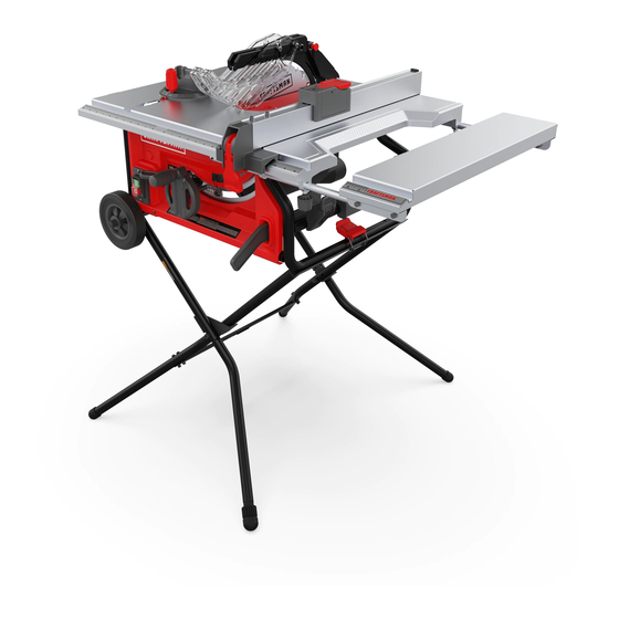
10 in. TABLE SAW
Model No.
315.218061
WARNING:
To reduce the risk of injury, the
user must read and understand the operator's
manual before using this product.
Customer
Help Line: 1-800-932-3188
Sears,
Roebuck
and Co., 3333 Beverly
Rd., Hoffman
Estates,
IL 60179
USA
Visit the Craftsman
web page: www.sears.com/craftsman
987000-585
1-7-10 (REV:04)
Save this manual
for future
reference
Advertisement
Table of Contents

Related Manuals for Craftsman 315.218061


Summary of Contents for Craftsman 315.218061
- Page 1 Customer Help Line: 1-800-932-3188 Sears, Roebuck and Co., 3333 Beverly Rd., Hoffman Estates, IL 60179 Visit the Craftsman web page: www.sears.com/craftsman 987000-585 Save this manual for future reference 1-7-10 (REV:04)
- Page 2 ONE YEAR FULL WARRANTY ON CRAFTSMAN TOOL If this Craftsman tool fails due to a defect in material or workmanship within one year from the date of purchase. Call 1-800-4-MY-HOME ® to arrange for free repair. If this tool is used for commercial or rental purposes, this warranty will apply for only ninety days from the date of purchase.
- Page 3 [] SECURE WORK. Use clamps or a vise to hold work WARNING: Read and understand all instruc- when practical. It's safer than using your hand and tions. Failure to follow all instructions listed below, frees both hands to operate tool. may result in electric shock, fire and/or serious [] DON'T OVERREACH.
- Page 4 work or around or over the blade while blade is rotat- ing. Never use brake fluids, gasoline, petroleum-based ing. Do not attempt to remove cut material when blade products, or any solvents to clean tool. is moving. [] STAY ALERT AND EXERCISE CONTROL. Watch BLADE COASTS AFTER BEING TURNED OFF.
- Page 5 [] ALWAYS SECURE WORKfirmly against r ipfence, c) Keeping riving knife/spreader/splitter, anti-kickback miterfence, o r mitergauge. pawls, and blade guard in place and operating. [] ALWAYS USE A PUSH STICK FOR RIPPING NAR- d) Not releasing the work before it is pushed all the ROW STOCK.
- Page 6 Someofthefollowing symbols maybeusedonthistool.Please studythemandlearn theirmeaning. Proper i nter- pretation ofthesesymbols willallowyouto operate thetool better andsafer. Indicates a potential personal injury hazard. Safety Alert To reduce the risk of injury, user must read and understand Read Operator's Manual operator's manual before using this product. Always wear eye protection marked to comply with ANSI Eye Protection...
- Page 7 Thefollowing signal w ordsandmeanings a reintended to explain the levels of riskassociated w iththisproduct. SYMBOL SIGNAL MEANING Indicates an imminently hazardous situation, which, if not avoided, will DANGER: result in death or serious injury. Indicates a potentially hazardous situation, which, if not avoided, could WARNING: result in death or serious injury.
- Page 8 EXTENSION CORDS SPEED AND WIRING The no-load speed of this tool is approximately 5,000 Use only 3-wire extension cords that have 3-prong r/min. (RPM). This speed is not constant and decreases grounding plugs and 3-pole receptacles that accept the under a load or with lower voltage. For voltage, the wiring tool's plug.
- Page 9 Anti=Kickback Non=Through Cuts Pawls (radial arm and table saws} A device which, when properly installed and maintained, Any cutting operation where the blade does not extend completely through the thickness of the workpiece. is designed to stop the workpiece from being kicked back toward the front of the saw during a ripping operation.
- Page 10 PRODUCT SPECiFiCATiONS Blade Arbor .............. 5/8 in. Rating ..........120 V, AC only, 60 Hz Blade Diameter ............10 in. Input ..............15 Amps. Blade Tilt ..............0 ° - 45 ° No Load Speed ........5,000 r/min. (RPM) Cutting Depth at 0°: ..........3-1/2 in.
- Page 11 KNOWYOURTABLESAW LEG STAND - Attached to the table saw base, the leg stand opens and closes with ease. See Figure 2. MITER FENCE WITH ADJUSTING CLAMP KNOB - The The safe use of this product requires an understanding of fence attaches to the sliding miter table and can be an- the information on the tool and in this operator's manual gled for miter and compound miter cuts as well as straight as well as a knowledge of the project you are attempt-...
- Page 12 OPERATING COMPONENTS WARNING: ALWAYS remove the switch key when The upper portion of the blade projects up through the the tool is not in use and keep it in a safe place. In table and is surrounded by an insert called the throat the event of a power failure, turn the switch off ( O } plate.
- Page 13 For maximum performance, it is recommended that you speed of this tool. Failure to heed this warning could use the Craftsman 36-tooth, 10 in. carbide combination result in personal injury. blade provided with your saw. Additional blade styles of the same high quality are available for specific operations such as ripping.
- Page 14 Thefollowing itemsareincluded withyourtablesaw: Fig. 5 A. Rip Fence ..................................B. Large Blade Wrench ..............................C. Small Blade Wrench ..............................D. Elbow ................................... E. Dust Bag ..................................R Bevel Handle Assembly .............................. G. Miter Fence with Miter Fence Holder and Adjusting Clamp Knob ................H.
- Page 15 UNPACKING WARNING: To avoid serious personal injury, always This product requires assembly. make sure the table saw is securely mounted to [] Carefully lift saw from the carton and place it on a level a workbench or an approved leg stand. NEVER work surface.
- Page 16 [] Place thenylonnutintotherecessed holeontheback SET-UP TEAR DOWN ofthe height/bevel adjusting handwheel andholdin place. [] Slidethe handle, s crew, a ndwasher i ntotheholeon theheight/bevel adjusting handwheel. [] Using a flathead screwdriver, turnthe screwclockwise andtightenin place. [] Push theendcapbackinplaceontheendof the handle. TO OPEN/CLOSE (SET-UP/TEAR DOWN) LEG STAND...
- Page 17 TO STORE THE TABLE SAW ACCESSORIES TO MOVE THE LEG STAND See Figures 8 - 9. See Figure 10. The table saw has two convenient storage areas (one on To move the leg stand: either side of the saw cabinet) specifically designed for [] Holding the leg stand firmly, pull the leg stand toward the saw's accessories.
- Page 18 TO CHECK SAW BLADE iNSTALLATiON TO INSTALL MITER FENCE See Figure 12. See Figure 13. [] Remove the miter fence from the miter fence storage CAUTION: To work properly, the saw blade teeth on the side of the saw cabinet. must point down toward the front of the saw.
- Page 19 FLAT TO INSTALL BLADE GUARD ASSEMBLY WASHER See Figure 14. Proper installation of the blade guard assembly means STARWASHER that the saw blade and spreader are in alignment. ALWAYS align the spreader to the saw blade prior to turn- ing on the table saw. WING NUT Lower the blade.
- Page 20 APPLICATIONS [] Always use the rip fence when rip cutting and the miter fence when cross cutting. This helps prevent twisting Youmayusethistoolforthepurposes listedbelow: the wood in the cut. [] Straight l inecuttingoperations s uchascrosscutting, ripping, m itering, b eveling, andcompound cutting [] Always use clean, sharp, and properly-set blades.
- Page 21 FEATHERBOARD HOW TO MOUNT A FEATHERBOARD See Figure 18. A featherboard is a device used to help control the workpiece by guiding it securely against the table or Remove the adjusting clamp knob, bolt, and washer from fence. Featherboards are especially useful when ripping the miter fence holder.
- Page 22 TYPESOF CUTS See Figure 19. There are six basic cuts: 1) the cross cut, 2) the rip cut, 3) the miter cut, 4) the bevel cross cut, 5) the bevel rip cut, and 6) the compound (bevel) miter cut. All other cuts are combinations of these basic six.
- Page 23 TO CHANGE BLADE DEPTH CHECKING SLIDING MITER TABLE AND See Figure 20. MAKING ADJUSTMENTS The blade depth should be set so that the outer points of TO POSITION THE SLIDING MITER TABLE the blade are higher than the workpiece by approximately See Figures 22 - 23.
- Page 24 Fig. 23 TO CHECK MITER BASE PARALLELISM See Figures 24 - 25. [] Unplug the saw. [] Set saw up as if you were preparing to make a cut. Tighten rail clamps, miter locking clamps, adjusting clamp knob, etc. Fig. 24 [] Slide miter table (A) to the front of miter base (B) as far as it will go.
- Page 25 TO CHECK MITER FENCE ALIGNMENT TO ADJUST THE MITER TABLE BASE See Figure 26. See Figure 27. Remember: Check all settings before loosening screws The miter fence must be perpendicular to the blade when for the following procedures. Once screws have been set at zero degrees.
- Page 26 TO ADJUSTQUICK-STOP BLADE See Figure 28. FENCE The quick-stop is preset at the factory to stop the miter fence at exactly 0 °. However, when sliding miter table BLADE adjustments are made, these adjustments may cause the quick-stop to need adjusting. Check quick-stop with miter scale set at 0°.
- Page 27 TO USE OUTFEED SUPPORT See Figure 31. The outfeed support slides to give the operator additional support for cutting long workpieces. [] With the table saw in the OFF position, stand behind the saw. [] Grasp the outfeed support with both hands and pull it OUTFEED until it is fully extended.
- Page 28 FRAMING HEELING (PARALLELING) THE BLADE SQUARE See Figures 33 - 35. WARNING: The blade must be square so the wood does not bind resulting in kickback. Failure to do so could result in serious personal injury. Do not loosen any screws for this adjustment until you have checked with a square and made test cuts to be sure adjustments are necessary.
- Page 29 MAKING CUTS The blade provided with the saw is a high-quality combi- nation blade suitable for ripping and cross cut operations. Carefully check all setups and rotate the blade one full SWITCH revolution to assure proper clearance before connect- ing saw to power source. Stand slightly to the side of the blade path to reduce the chance of injury should kickback Occur.
- Page 30 MAKING A RiP CUT MAKING A MITER See Figure 38. See Figure 39. WARNING: Make sure the blade guard assembly WARNING: Make sure the blade guard assembly is installed and working properly to avoid serious is installed and working properly to avoid possible possible injury.
- Page 31 VIEWEDFROMTHE FRONT,BELOWTHE TABLE SAW [] Set the miter fence to 0° and tighten the adjusting clamp knob. HEIGHT/BEVEL [] Make sure the wood is clear of the blade before turning ADJUSTING on the saw. HANDWHEEL TO LOOSEN [] Turn the saw on. [] Let the blade build up to full speed before moving the workpiece into the blade.
- Page 32 [] Position the ripfencethe desired distance fromthe [] Remove the rip fence. bladeforthecut andsecurely lockthehandle. [] Unlock the bevel locking lever. [] Makesurethewoodisclearofthebladebefore turning [] Adjust the bevel angle to the desired setting. onthesaw. [] Lock the bevel locking lever. [] Whenrippinga longworkpiece, place a support t he sameheight a sthetablesurface behind the sawfor [] Set the blade to the correct depth for the workpiece.
- Page 33 MAKING A NON=THROUGH WARNING: Never make freehand cuts (cuts without See Figure 45. the miter fence or rip fence), which can result in Non-through cuts (made with a standard 10 in. blade) can serious injury. be made with the grain (ripping) or across the grain (cross Place a support the same height as the top of the saw cut).
- Page 34 MAKING A DADO CUT [] Use a push block or push stick to move the wood through the cut past the blade. Never push a small See Figure 46. piece of wood into the blade with your hand, always An optional dado throat plate is required for this procedure use a push stick.
- Page 35 BLADE WARNING" Before performing any adjustment, make sure the tool is unplugged from the power supply. Failure to heed this warning could result in WAS_ Sv_.._ BLADE serious personal injury. WARNING-" Blades coast after turn off. Possible serious injury can occur if hands come in contact BLADE SHAFT with blade.
- Page 36 TO CHECK THE ALIGNMENT OF THE RiP FENCE TO CHECK AND ALIGN THE SPREADER, BLADE, AND BLADE GUARD ASSEMBLY TO THE BLADE See Figure 50. See Figure 51. if the blade guard assembly is out of alignment with the [] Unplug the saw. saw blade, adjust the alignment of the blade guard [] Raise the locking lever to permit the rip fence to be assembly.
- Page 37 [] Ifthetwo dimensions a renotthe same, l oosen thetwo BLADE screwsonthefenceandalignit. 0° ADJUSTMENT COMBINATION BOLT SQUARE [] Retighten t hetwoscrews. [] Maketwoor threetestcutson scrapwood.If thecuts arenottrue,repeat t he process. _lb, WARNING:Beforeplugging thesawback in to make test cuts, make sure the switch is in the OFF position and the blade guard is in place.
- Page 38 WARNING: Do not at any time let brake fluids, WARNING: When servicing, use only identical replacement parts. Use of any other parts may create gasoline, petroleum-based products, penetrating a hazard or cause product damage. oils, etc., come in contact with plastic parts. Chemicals can damage, weaken, or destroy plastic WARNING: Always wear safety goggles or safety...
- Page 39 CAUSE SOLUTION I PROBLEM Excess vibration. Blade is out of balance. Replace blade. Blade is damaged. Replace blade. Saw is not mounted securely. Tighten all hardware. Work surface is uneven. Reposition on flat surface. Adjust legs of optional stand. Blade is warped. Check saw blade installation.
- Page 40 PROBLEM CAUSE SOLUTION Saw does not make accurate Positive stops inside cabinet need Adjust positive stops. 90 ° or 45 ° cuts. adjusting (Bevel Cuts). Adjust the miter gauge. Miter gauge is misaligned (Miter Cuts). Height/bevel adjusting hand- Clean the gears or screw post. Gears or screw post inside wheel is hard to turn.
- Page 41 CRAFTSMAN 10 in. TABLE SAW- MODEL NO. 315.218061 Figure B _--143 Figure C 67 _ _ 58 SEE NOTE \\i i Figure D p ....... NOTE: The assembly shown represents an important part of the double insulated system. To avoid the possibility of alteration or damage to the system, service should be performed by your nearest Sears Repa=r Center.
- Page 42 CRAFTSMAN 10 in. TABLE SAW- MODEL NO. 315.218061 The model number will be found on a plate attached to the motor housing. Always mention the model number in all correspondence regarding your Table Saw or when ordering repair parts. PARTS LiST...
- Page 43 CRAFTSMAN 10 in. TABLE SAW- MODEL NO. 315.218061 number in all correspondence regarding your Table Saw or when ordering repair parts. The model number will be found on a plate attached to the motor housing. Always mention the model PARTS LiST...
- Page 44 CRAFTSMAN 10 in. TABLE SAW- MODEL NO. 315.218061 FIGURE A: SLiDiNG MITER TABLE Part Number Description Qty. A134010802 Sliding Miter Table Assembly (Inc. Key No. 1-8) 1 410561013 Screw w/Washer (M5 x 16 mm) ..4 0134010104-126 Miter Table ........
- Page 45 CRAFTSMAN 10 in. TABLE SAW- MODEL NO. 315.218061 FIGURE C: RIP FENCE Part Number Description Qty. A134010901 Rip Fence Assembly (Incl. Key No.1-17) ....1 1 411071001 Lock Nut (M6) ......1 412011030 Washer (6.5 x 16 x 1-0 .... 3 3 0121010310 Rear Clamping Plate ....
- Page 46 CRAFTSMAN 10 in. TABLE SAW- MODEL NO. 315.218061 REPLACEMENT PARTS FOR LEG STAND ASSEMBLY Part Part Number Number Description Qty. Description Qty. 9134015335704 0131010232 Unlock Label, Leg ..... 1 Adjusting Ring ......089110114001 410031714 Latch Bar w/grommet ....1 Bolt (5/8-11 x 88.9 mm) .... 1 Screw ........
Need help?
Do you have a question about the 315.218061 and is the answer not in the manual?
Questions and answers