Table of Contents
Advertisement
OPERATOR'S MANUAL
10 in. TABLE SAW
Model No.
315.218060
WARNING:
To reduce the risk of injury, the
user must read and understand the operator's
manual before using this product.
Customer Help Line: 1-800-932-3188
Sears, Roebuck and Co., 3333 Beverly Rd., Hoffman Estates, IL 60179 USA
Visit the Craftsman web page: www.sears.com/craftsman
983000-696
4-03-06 (Rev:02)
Save this manual for future reference
1
R
Advertisement
Table of Contents

Related Manuals for Craftsman 315.218060


Summary of Contents for Craftsman 315.218060
- Page 1 Customer Help Line: 1-800-932-3188 Sears, Roebuck and Co., 3333 Beverly Rd., Hoffman Estates, IL 60179 USA Visit the Craftsman web page: www.sears.com/craftsman 983000-696 Save this manual for future reference 4-03-06 (Rev:02)
-
Page 2: Table Of Contents
ONE YEAR FULL WARRANTY ON CRAFTSMAN TOOL If this Craftsman tool fails due to a defect in material or workmanship within one year from the date of purchase. Call 1-800-4-MY-HOME ® to arrange for free repair. If this tool is used for commercial or rental purposes, this warranty will apply for only ninety days from the date of purchase. -
Page 3: General Safety Rules
GENERAL SAFETY RULES n SECURE WORK. Use clamps or a vise to hold work WARNING: Read and understand all instruc- when practical. It’s safer than using your hand and tions. Failure to follow all instructions listed below, frees both hands to operate tool. may result in electric shock, fire and/or serious n DON’T OVERREACH. -
Page 4: Specific Safety Rules
GENERAL SAFETY RULES work or around or over the blade while blade is ing. Never use brake fluids, gasoline, petroleum-based rotating. Do not attempt to remove cut material when products, or any solvents to clean tool. blade is moving. n STAY ALERT AND EXERCISE CONTROL. Watch n BLADE COASTS AFTER BEING TURNED OFF. - Page 5 SPECIFIC SAFETY RULES n NEVER perform any operation “freehand” which n AVOID AWKWARD OPERATIONS AND HAND POSITIONS where a sudden slip could cause your means using only your hands to support or guide the workpiece. Always use either the rip fence or miter hand to move into the cutting tool.
-
Page 6: Symbols
SYMBOLS Some of the following symbols may be used on this tool. Please study them and learn their meaning. Proper interpretation of these symbols will allow you to operate the tool better and safer. SYMBOL NAME DESIGNATION/EXPLANATION Volts Voltage Amperes Current Hertz Frequency (cycles per second) -
Page 7: Save These Instructions
SYMBOLS The following signal words and meanings are intended to explain the levels of risk associated with this product. SYMBOL SIGNAL MEANING Indicates an imminently hazardous situation, which, if not avoided, will DANGER: result in death or serious injury. Indicates a potentially hazardous situation, which, if not avoided, could WARNING: result in death or serious injury. -
Page 8: Electrical
ELECTRICAL EXTENSION CORDS ELECTRICAL CONNECTION This tool is powered by a precision built electric motor. Use only 3-wire extension cords that have 3-prong It should be connected to a power supply that is 120 grounding plugs and 3-pole receptacles that accept the volts, 60 Hz, AC only (normal household current). -
Page 9: Glossary Of Terms
GLOSSARY OF TERMS Non-Through Cuts Anti-Kickback Pawls (radial arm and table saws) Any cutting operation where the blade does not extend A device which, when properly installed and maintained, completely through the thickness of the workpiece. is designed to stop the workpiece from being kicked back toward the front of the saw during a ripping operation. -
Page 10: Features
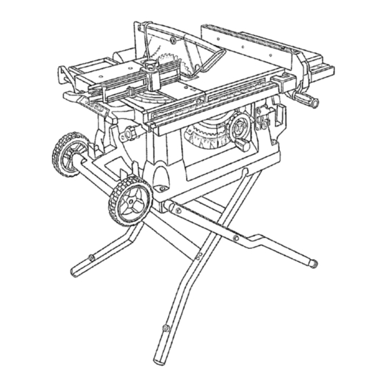
FEATURES PRODUCT SPECIFICATIONS Rating ..........120 V, 60 Hz, AC only Blade Arbor .............. 5/8 in. Blade Diameter............10 in. Input ..............15 Amperes Blade Tilt ..............0˚ - 45˚ No Load Speed ..........5,000/min. Net Weight without Leg Stand ......61.5 lbs. Cutting Depth at 0˚: ..........3-1/2 in. - Page 11 FEATURES KNOW YOUR TABLE SAW LEG STAND - Attached to the table saw base, the leg stand opens and closes with ease. See Figure 2. MITER FENCE- The fence attaches to the sliding miter Before attempting to use this product, familiarize yourself table and can be angled for miter and compound miter with all operating features and safety rules.
- Page 12 FEATURES OPERATING COMPONENTS WARNING: Always remove the switch key when The upper portion of the blade projects up through the the tool is not in use and keep it in a safe place. In table and is surrounded by an insert called the throat the event of a power failure, turn the switch OFF plate.
-
Page 13: Tools Needed
Do not use blades rated less than the For maximum performance, it is recommended that you speed of this tool. Failure to heed this warning could use the Craftsman 36-tooth, 10 in. carbide combination result in personal injury. blade provided with your saw. Additional blade styles of the same high quality are available for specific operations such as ripping. -
Page 14: Loose Parts
LOOSE PARTS The following items are included with your table saw: Fig. 5 A. Rip Fence ..................................1 B. Large Blade Wrench..............................1 C. Small Blade Wrench ..............................1 D. Elbow ..................................1 E. Dust Bag ..................................1 F. Bevel Handle Assembly .............................. 1 G. -
Page 15: Assembly
ASSEMBLY UNPACKING MOUNTING HOLES This product requires assembly. This tool comes mounted to a leg stand. If you chose to remove the leg stand, the table saw must be mounted to a n Carefully lift saw from the carton and place it on a level firm supporting surface such as a workbench or leg stand. - Page 16 ASSEMBLY TO OPEN/CLOSE (SET-UP/TEAR DOWN) THE SET-UP TEAR DOWN LEG STAND See Figure 7. To open (set-up) the leg stand: n Step 1: With the saw table on end and standing to the side, use your left hand to pull the leg stand latch towards you. n Step 2: Once the leg stand is released from the table saw base, ease the legs of the stand down.
- Page 17 ASSEMBLY TO STORE THE TABLE SAW ACCESSORIES TO MOVE THE LEG STAND See Figures 8 - 9. See Figure 10. The table saw has two convenient storage areas (one on To move the leg stand: either side of the saw cabinet) specifically designed for n Holding the leg stand firmly, pull the leg stand toward the saw’s accessories.
- Page 18 ASSEMBLY TO CHECK SAW BLADE INSTALLATION TO INSTALL MITER FENCE See Figure 12. See Figure 13. n Remove the miter fence from the miter fence storage CAUTION: To work properly, the saw blade teeth on the side of the saw cabinet. must point down toward the front of the saw.
-
Page 19: Operation
ASSEMBLY TO INSTALL BLADE GUARD ASSEMBLY ANTI-KICKBACK PAWLS See Figure 14. Proper installation of the blade guard assembly means that the saw blade and spreader are in alignment. ALWAYS align the spreader to the saw blade prior to turn- ing on the table saw. n Lower the blade. - Page 20 OPERATION APPLICATIONS You may use this tool for the purposes listed below: n Straight line cutting operations such as cross cutting, ripping, mitering, beveling, and compound cutting n Dado or molding cuts with optional accessories PUSH STICKS n Cabinet making and woodworking NOTE: This table saw is designed to cut wood and wood composition products only.
- Page 21 OPERATION TYPES OF CUTS See Figure 17. There are six basic cuts: 1) the cross cut, 2) the rip cut, 3) the miter cut, 4) the bevel cross cut, 5) the bevel rip cut, and 6) the compound (bevel) miter cut. All other cuts are combinations of these basic six.
- Page 22 OPERATION FEATHERBOARD HOW TO MOUNT A FEATHERBOARD See Figure 19. A featherboard is a device used to help control the workpiece by guiding it securely against the table or Remove the adjusting clamp knob, bolt, and washer from fence. Featherboards are especially useful when ripping the miter fence holder.
- Page 23 OPERATION CHECKING SLIDING MITER TABLE AND TO CHANGE BLADE DEPTH See Figure 20. MAKING ADJUSTMENTS The blade depth should be set so that the outer points of TO POSITION THE SLIDING MITER TABLE the blade are higher than the workpiece by approximately See Figures 22- 23.
- Page 24 OPERATION Fig. 23 TO CHECK MITER BASE PARALLELISM See Figures 24 - 25. n Unplug the saw. n Set saw up as if you were preparing to make a cut. Tighten rail clamps, miter locking clamps, adjusting clamp, etc. n Slide miter table (A) to the front of miter base (B) as far Fig.
- Page 25 OPERATION TO CHECK MITER FENCE ALIGNMENT TO ADJUST THE MITER BASE See Figure 26. See Figure 27. Remember: Check all settings before loosening screws The miter fence must be perpendicular to the blade when for the following procedures. Once screws have been set at zero degrees.
- Page 26 OPERATION TO ADJUST QUICK-STOP SCALE FENCE BLADE See Figure 28. The quick-stop is preset at the factory to stop the miter fence at exactly 0°. However, when sliding miter table adjustments are made, these adjustments may cause the quick-stop to need adjusting. Check quick-stop with miter 2 in.
- Page 27 OPERATION TO USE OUTFEED SUPPORT See Figure 31. The outfeed support slides to give the operator additional support for cutting long workpieces. n With the table saw in the OFF position, stand behind the saw. n Grasp the outfeed support with both hands and pull it until it is fully extended.
- Page 28 OPERATION HEELING (PARALLELING) THE BLADE SCREWS (3) See Figures 33 - 35. WARNING: The blade must be square so the wood does not bind resulting in kickback. Failure to do so could result in serious personal injury. Do not loosen any screws for this adjustment until you have checked with a square and made test cuts to be sure adjustments are necessary.
-
Page 29: Making Cuts
OPERATION MAKING CUTS The blade provided with the saw is a high-quality combi- nation blade suitable for ripping and cross cut operations. SWITCH SWITCH WARNING: Do not use blades rated less than the speed of this tool. Failure to heed this warning could result in personal injury. - Page 30 OPERATION MAKING A MITER CUT n Place a support (the same height as saw table) behind the saw for the cut work. See Figure 39. n Make sure the wood is clear of the blade before turning It is recommended you make test cuts on scrap wood. on the saw.
- Page 31 OPERATION MAKING A BEVEL RIP CUT VIEWED FROM THE FRONT, BELOW THE TABLE SAW See Figure 42. HEIGHT/BEVEL ADJUSTING It is recommended you make test cuts on scrap wood. HANDWHEEL WARNING: The rip fence must be on the left side TO LOOSEN of the blade to avoid trapping the wood and causing kickback.
- Page 32 OPERATION n When the cut is made, turn the saw off. Wait for the n Loosen the lock knob on the miter gauge, set the miter blade to come to a complete stop before removing the gauge to the desired angle and tighten the lock knob. workpiece.
- Page 33 OPERATION MAKING A LARGE PANEL CUT MAKING A NON-THROUGH CUT See Figure 45. See Figure 44. Non-through cuts can be made with the grain (ripping) or Make sure the saw is properly secured to a work surface across the grain (cross cut). The use of a non-through cut to avoid tipping from the weight of a large panel.
- Page 34 OPERATION MAKING A DADO CUT WARNING: Never feed wood with your hands when See Figure 46. making any non-through cut such as rabbets or An optional dado throat plate (part number 0134010313) dadoes. To avoid personal injury, always use push is required for this procedure.
-
Page 35: Adjustments
ADJUSTMENTS BLADE WARNING: Before performing any adjustment, WASHER BLADE make sure the tool is unplugged from the power supply. Failure to heed this warning could result in serious personal injury. ARBOR SHAFT WARNING: Blades coast after turn off. Possible serious injury can occur if hands come in contact BLADE with blade. - Page 36 ADJUSTMENTS TO CHECK AND ALIGN THE SPREADER, SAW TO CHECK THE ALIGNMENT OF THE RIP FENCE BLADE, AND BLADE GUARD ASSEMBLY TO THE BLADE See Figure 51. See Figure 50. n Unplug the saw. If the blade guard assembly is out of alignment with the saw blade, adjust the alignment of the blade guard n Raise the locking lever to permit the rip fence to be assembly.
- Page 37 ADJUSTMENTS BLADE n If the two dimensions are not the same, loosen the two screws on the fence and align it. 0° ADJUSTMENT COMBINATION SQUARE BOLT n Retighten the two screws. n Make two or three test cuts on scrap wood. If the cuts are not true, repeat the process.
-
Page 38: Maintenance
MAINTENANCE n Periodically check all clamps, nuts, bolts, screws, and WARNING: When servicing, use only identical belts for tightness and condition. Make sure the throat replacement parts. Use of any other parts may create plate is in good condition and in position. a hazard or cause product damage. -
Page 39: Troubleshooting
TROUBLESHOOTING PROBLEM CAUSE SOLUTION Excess vibration. Blade is out of balance. Replace blade. Blade is damaged. Replace blade. Saw is not mounted securely. Tighten all hardware. Work surface is uneven. Reposition on flat surface. Adjust legs of optional stand. Blade is warped. Check saw blade installation. - Page 40 TROUBLESHOOTING PROBLEM CAUSE SOLUTION Saw does not make accurate Positive stops inside cabinet need Adjust positive stops. 90˚ or 45˚ cuts. adjusting (Bevel Cuts). Adjust the miter gauge. Miter gauge is misaligned (Miter Cuts). Height/bevel adjusting hand- Clean the gears or screw post. Gears or screw post inside wheel is hard to turn.
-
Page 41: Exploded View
CRAFTSMAN 10 in. TABLE SAW – MODEL NO. 315.218060 Figure B Figure A 43 137 Figure C SEE NOTE SEE NOTE 73 74 77 78 100 99 Figure D NOTE : The assembly shown represents an important part of the double insulated system. To avoid the possibility of alteration or damage to the system, service should be performed by your nearest Sears Repair Center. - Page 42 CRAFTSMAN 10 in. TABLE SAW – MODEL NO. 315.218060 The model number will be found on a plate attached to the motor housing. Always mention the model number in all correspondence regarding your Table Saw or when ordering repair parts.
- Page 43 CRAFTSMAN 10 in. TABLE SAW – MODEL NO. 315.218060 The model number will be found on a plate attached to the motor housing. Always mention the model number in all correspondence regarding your Table Saw or when ordering repair parts.
- Page 44 CRAFTSMAN 10 in. TABLE SAW – MODEL NO. 315.218060 FIGURE A: SLIDING MITER TABLE Key Part Number Description Qty. A134010802 A134010802 Sliding Miter Table Assembly Sliding Miter Table Assembly (Incl. Key No. 1 - 8) (Incl. Key No. 1 - 8)
- Page 45 CRAFTSMAN 10 in. TABLE SAW – MODEL NO. 315.218060 FIGURE C: RIP FENCE Key Part No. Number Description Qty. A134010901 Rip Fence Assembly (Incl. Key No.1 - 19) ....1 1 411071001 * Nut (M6) ........2 2 412011030 Washer (6.5 x 16 x 1T) ....3 3 0121010310 Rear Clamping Plate ....1...
- Page 46 CRAFTSMAN 10 in. TABLE SAW – MODEL NO. 315.218060 5 4 3 REPLACEMENT PARTS FOR LEG STAND ASSEMBLY Key Part Key Part Key Part Key Part Key Part Key Part Key Part Key Part Key Part Number Number Number Number...
Need help?
Do you have a question about the 315.218060 and is the answer not in the manual?
Questions and answers